EP0216645A2 - Vorrichtung zur Verhinderung der relativen Rückbewegung zweier ineinander steckbarer Teile, von denen einer manuell bedient wird - Google Patents
Vorrichtung zur Verhinderung der relativen Rückbewegung zweier ineinander steckbarer Teile, von denen einer manuell bedient wird Download PDFInfo
- Publication number
- EP0216645A2 EP0216645A2 EP86401594A EP86401594A EP0216645A2 EP 0216645 A2 EP0216645 A2 EP 0216645A2 EP 86401594 A EP86401594 A EP 86401594A EP 86401594 A EP86401594 A EP 86401594A EP 0216645 A2 EP0216645 A2 EP 0216645A2
- Authority
- EP
- European Patent Office
- Prior art keywords
- finger
- relative movement
- members
- movement
- male
- Prior art date
- Legal status (The legal status is an assumption and is not a legal conclusion. Google has not performed a legal analysis and makes no representation as to the accuracy of the status listed.)
- Granted
Links
Images

Classifications
-
- H—ELECTRICITY
- H01—ELECTRIC ELEMENTS
- H01R—ELECTRICALLY-CONDUCTIVE CONNECTIONS; STRUCTURAL ASSOCIATIONS OF A PLURALITY OF MUTUALLY-INSULATED ELECTRICAL CONNECTING ELEMENTS; COUPLING DEVICES; CURRENT COLLECTORS
- H01R13/00—Details of coupling devices of the kinds covered by groups H01R12/70 or H01R24/00 - H01R33/00
- H01R13/62—Means for facilitating engagement or disengagement of coupling parts or for holding them in engagement
- H01R13/623—Casing or ring with helicoidal groove
-
- G—PHYSICS
- G05—CONTROLLING; REGULATING
- G05G—CONTROL DEVICES OR SYSTEMS INSOFAR AS CHARACTERISED BY MECHANICAL FEATURES ONLY
- G05G7/00—Manually-actuated control mechanisms provided with one single controlling member co-operating with one single controlled member; Details thereof
- G05G7/02—Manually-actuated control mechanisms provided with one single controlling member co-operating with one single controlled member; Details thereof characterised by special provisions for conveying or converting motion, or for acting at a distance
- G05G7/08—Manually-actuated control mechanisms provided with one single controlling member co-operating with one single controlled member; Details thereof characterised by special provisions for conveying or converting motion, or for acting at a distance in which repeated movement of the controlling member moves the controlling member through a cycle of distinct positions
-
- Y—GENERAL TAGGING OF NEW TECHNOLOGICAL DEVELOPMENTS; GENERAL TAGGING OF CROSS-SECTIONAL TECHNOLOGIES SPANNING OVER SEVERAL SECTIONS OF THE IPC; TECHNICAL SUBJECTS COVERED BY FORMER USPC CROSS-REFERENCE ART COLLECTIONS [XRACs] AND DIGESTS
- Y10—TECHNICAL SUBJECTS COVERED BY FORMER USPC
- Y10T—TECHNICAL SUBJECTS COVERED BY FORMER US CLASSIFICATION
- Y10T29/00—Metal working
- Y10T29/49—Method of mechanical manufacture
- Y10T29/49002—Electrical device making
- Y10T29/49117—Conductor or circuit manufacturing
- Y10T29/49194—Assembling elongated conductors, e.g., splicing, etc.
- Y10T29/49195—Assembling elongated conductors, e.g., splicing, etc. with end-to-end orienting
Definitions
- the invention relates to any system in which one of two members fitted one inside the other is moved manually relative to the other, along a trajectory traveled in one direction, then in the opposite direction.
- the invention provides a device consisting on the one hand, by a finger mounted in a support secured to one of the members, movable in a plane perpendicular to the general direction of relative movement and subjected to the action of an elastic means urging it towards an average position of rest and, on the other hand, by a ramp for guiding said finger, provided on the second member, having a general direction substantially parallel to that of relative movement and having at a point, a stop surface substantially perpendicular to the relative movement and opposite which the finger is placed when the stroke reaches the position from which the reversal of the direction of operation must be prohibited.
- the finger is constituted by a metal rod which passes through a diametrical slot at the bottom of a cylindrical case and which is provided with a flat head applying, at rest, against the inside face of the cover of the case, while that a conical coil spring is interposed between said flat head and the inner face of the bottom of the housing.
- the device according to the invention comprises a movable finger cooperating with a ramp.
- the finger 11 is carried by the female member, symbolized by the housing 10 of said finger, and the ramp by the male member, but, of course, it could be the reverse.
- the coupling of the male organ 12 and of the female member 10 comprises a final phase which is a rotational movement around the axis X of said male member.
- the finger 11 is movable in a plane P passing through the axis X, that is to say in a plane perpendicular to the general direction of the relative movement of the male organ 12 relative to the female organ 10.
- the organ male 12 carries a projection 13 forming a double ramp, intended to cooperate with and guide the movable finger 11.
- the projection 13 has the general shape of a curvilinear rhombus whose ends of the long diagonal 13 c delimit two half-perimeters 13a and 13 b followed by finger 11 respectively in the stroke in a direction F 1 and in the reverse stroke F 2 .
- a notch 14 in the form of a wolf tooth has an abrupt face whose plane is substantially parallel to the axis X and therefore substantially perpendicular to the direction F 2 of the relative movement of the two organs.
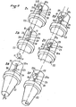
- the mounting of the finger 11 in its housing 10 is clearly shown in Figures 3 and 4.
- the finger consists of a metal rod which passes through a diametrical slot 15 of the bottom 16 of the cylindrical housing 10 and which is provided with a flat head 17 applying at rest against the inner face of the cover 18 of the housing.
- a conical coil spring 19 is interposed between said flat head 17 and the inner face of the bottom 16 of the housing. It can be seen that the finger can oscillate in the diametrical plane P of the housing 10 corresponding to the slot 15 by deforming the spring 19 and that the latter tends to bring the finger back into coincidence with the axis Z of the housing 10.
- the operation of the device is as follows.
- the male member 12 being fitted into the female member (symbolized by 10), the coupling takes place by imparting to the member 12 a rotational movement F 1 .
- the finger 11 is opposite a point of the half-perimeter 13a of the projection 13 (FIG. 1A).
- the finger is pushed back by the ramp opposite the member 12 and slides on the projection 13 by traversing the half-perimeter 13a (FIGS. 1B and 1).
- the finger 11 At the end of the coupling, the finger 11 is at the end of the large diagonal of the projection ( Figure 1 D ) or a little beyond and, under the action of the spring 19, returns to its initial axial position opposite a point of the half-perimeter 13 b .
- the male organ is given a reverse rotation F 2 of F 1
- the finger 11 comes into contact with the half-perimeter 13 b and slides on the latter whose curvature pushes it back towards reverse of nesting ( Figure 1 E ).
- the notch 14 in the form of a wolf tooth is formed, the abrupt face of which constitutes a stop surface substantially parallel to the axis X and, under the action of the spring 19, the finger 11 is housed in this hook (FIG. 1 F ) preventing any rotation F 1 . While continuing the rotation F 2 , the finger 11 traverses the entire half-perimeter 13 b until it escapes to return to the initial position of FIG. 1 A.
- the notch 14 could be provided on the half-perimeter 13 a to prohibit the reversal of the rotation along F 1 , or even that a notch may be formed on each of the half-areas 13a and 13b to prohibit the reversal of motion, both during the coupling stroke than during the separation stroke.
- FIGS. 2A to 2 Fl the coupling of the male member 22 and the female member 10 takes place at the end of a relative movement F 3 of axial translation.
- a movable finger 11 housed in a housing 10 symbolizing the female member, the finger being able to oscillate in the plane P perpendicular to F 3 .
- the guide ramp 23 carried by the male member 22 is constituted by two oblong parallelipipedic ribs 25 and 26.
- the rib 25 which cooperates first with the finger 11 during the coupling stroke F is slightly oblique with respect to the direction of the relative movement, while the rib 26 is parallel to this direction, the end faces closest to the two ribs being offset laterally and the spacing 24 between said ends being greater than the diameter of the finger 11.
- the finger 11 Before the two bodies fit together (FIG. 2A), the finger 11 is in its rest position, facing a point on the lateral face 25 of the rib 25.
- the obliquity of the rib 25 makes the movable finger deviates from the path of the rib 26, sliding on the face 25, when the translation of the member 22 continues (FIG. 2B ).
- the finger 11 arrives at the end of the rib 25 (FIG. 2 C ) then under the action of the spring 19 comes to bear against the face 26 a of the rib 26 (FIG. 2 D ) .
- the ramp with a notch in FIG. 1 can be adapted for an axial translational movement, as the two-part ramp in FIG. 2 can be adapted for a rotational movement.
- the device according to the invention finds a particularly interesting application for electrical outlets, in order to prohibit any attempt to re-engage, when the separation maneuver reaches the position corresponding to the cut-off. contacts ( Figures 1 F and 2 F ). It should then continue the operation until the end, to return to a position where the coupling becomes possible ( Figure 1. And 2 A).
Landscapes
- Physics & Mathematics (AREA)
- General Physics & Mathematics (AREA)
- Engineering & Computer Science (AREA)
- Automation & Control Theory (AREA)
- Details Of Connecting Devices For Male And Female Coupling (AREA)
- Surgical Instruments (AREA)
- Orthopedics, Nursing, And Contraception (AREA)
- Toys (AREA)
Applications Claiming Priority (2)
| Application Number | Priority Date | Filing Date | Title |
|---|---|---|---|
| FR8512569A FR2586460B1 (fr) | 1985-08-21 | 1985-08-21 | Dispositif anti-inversion du mouvement relatif de deux organes, respectivement male et femelle, dont l'un est actionne manuellement |
| FR8512569 | 1985-08-21 |
Publications (3)
| Publication Number | Publication Date |
|---|---|
| EP0216645A2 true EP0216645A2 (de) | 1987-04-01 |
| EP0216645A3 EP0216645A3 (en) | 1988-03-09 |
| EP0216645B1 EP0216645B1 (de) | 1992-09-23 |
Family
ID=9322317
Family Applications (1)
| Application Number | Title | Priority Date | Filing Date |
|---|---|---|---|
| EP86401594A Expired - Lifetime EP0216645B1 (de) | 1985-08-21 | 1986-07-17 | Vorrichtung zur Verhinderung der relativen Rückbewegung zweier ineinander steckbarer Teile, von denen einer manuell bedient wird |
Country Status (9)
| Country | Link |
|---|---|
| US (1) | US4732567A (de) |
| EP (1) | EP0216645B1 (de) |
| JP (1) | JPH0821445B2 (de) |
| CN (1) | CN1004160B (de) |
| CA (1) | CA1291799C (de) |
| DE (1) | DE3686800T2 (de) |
| FR (1) | FR2586460B1 (de) |
| IN (1) | IN168042B (de) |
| MX (1) | MX168064B (de) |
Families Citing this family (1)
| Publication number | Priority date | Publication date | Assignee | Title |
|---|---|---|---|---|
| CN101709734B (zh) * | 2009-12-22 | 2012-05-23 | 中国航空工业集团公司第六三一研究所 | C型锁紧拔插装置 |
Family Cites Families (8)
| Publication number | Priority date | Publication date | Assignee | Title |
|---|---|---|---|---|
| FR1220035A (fr) * | 1959-05-25 | 1960-05-20 | Silec Liaisons Elec | Raccords électriques |
| IT699906A (de) * | 1962-06-16 | 1900-01-01 | ||
| CH441474A (de) * | 1965-05-18 | 1967-08-15 | Levy Fils Fa | Druckknopfbetätigter Schalter für Hausinstallation |
| DE1765720A1 (de) * | 1968-07-05 | 1971-09-09 | Siemens Ag | Drucktastenschalter |
| US3824362A (en) * | 1973-05-23 | 1974-07-16 | Illinois Tool Works | Alternate action switch mechanism |
| FR2531577A1 (fr) * | 1982-08-09 | 1984-02-10 | Marechal Sepm | Contact electrique a pression a pouvoir de fermeture et d'ouverture incorpore |
| EP0106931B1 (de) * | 1982-10-21 | 1986-04-30 | Société d'Exploitation des Procédés Maréchal S.E.P.M. (Société Anonyme) | Steckdose mit Schnappeinschaltung und -trennung |
| US4572601A (en) * | 1984-12-17 | 1986-02-25 | Eaton Corporation | Push-push bayonet lamp socket |
-
1985
- 1985-08-21 FR FR8512569A patent/FR2586460B1/fr not_active Expired
-
1986
- 1986-07-11 IN IN614/DEL/86A patent/IN168042B/en unknown
- 1986-07-17 DE DE8686401594T patent/DE3686800T2/de not_active Expired - Fee Related
- 1986-07-17 EP EP86401594A patent/EP0216645B1/de not_active Expired - Lifetime
- 1986-07-18 CA CA000514098A patent/CA1291799C/fr not_active Expired - Lifetime
- 1986-08-11 MX MX003415A patent/MX168064B/es unknown
- 1986-08-12 CN CN86105317.6A patent/CN1004160B/zh not_active Expired
- 1986-08-13 US US06/896,062 patent/US4732567A/en not_active Expired - Lifetime
- 1986-08-21 JP JP61194125A patent/JPH0821445B2/ja not_active Expired - Lifetime
Also Published As
| Publication number | Publication date |
|---|---|
| MX168064B (es) | 1993-05-03 |
| FR2586460B1 (fr) | 1987-11-06 |
| CN1004160B (zh) | 1989-05-10 |
| EP0216645A3 (en) | 1988-03-09 |
| CA1291799C (fr) | 1991-11-05 |
| AU6062786A (en) | 1987-02-26 |
| FR2586460A1 (fr) | 1987-02-27 |
| CN86105317A (zh) | 1987-02-18 |
| EP0216645B1 (de) | 1992-09-23 |
| US4732567A (en) | 1988-03-22 |
| DE3686800T2 (de) | 1993-02-11 |
| JPS6244964A (ja) | 1987-02-26 |
| JPH0821445B2 (ja) | 1996-03-04 |
| DE3686800D1 (de) | 1992-10-29 |
| AU583642B2 (en) | 1989-05-04 |
| IN168042B (de) | 1991-01-26 |
Similar Documents
| Publication | Publication Date | Title |
|---|---|---|
| EP1437260B1 (de) | Auf zwei Achsen rotierbarer Fahrzeugaussenrückspiegel | |
| EP1431845A1 (de) | Uhrgehäuse | |
| EP0016683B1 (de) | Fahrzeugrückspiegel | |
| EP3561608A1 (de) | Befestigungsleiste eines armbands an einer armbanduhr, die mit zwei einziehbaren drehzapfen ausgestattet ist | |
| FR2958962A1 (fr) | Commande d'ouverture interieure d'un ouvrant de vehicule automobile et vehicule automobile equipee d'une telle commande. | |
| EP0216645B1 (de) | Vorrichtung zur Verhinderung der relativen Rückbewegung zweier ineinander steckbarer Teile, von denen einer manuell bedient wird | |
| EP1709655B1 (de) | Bistabile betätigungsvorrichtung einer bewegbaren, nicht durchgehenden, welle und damit versehener schalter für batterie | |
| EP1600653B1 (de) | Führungsfeder für ein Reibelement und Scheibenbremse mit mindestens einer solchen Feder | |
| EP3434536B1 (de) | Befestigungsvorrichtung für ein gestängesystem zur betätigung von scheibenwischern | |
| EP0675022B1 (de) | Elektrischer Schalter für Fahrtrichtungsanzeige eines Fahrzeugs | |
| EP0422976B1 (de) | Elastische Rückstellvorrichtung, insbesondere für einen Schaltfinger eines Kraftfahrzeuggetriebes | |
| EP0248716A1 (de) | Schalter für Kraftfahrzeuge | |
| FR2499177A1 (fr) | Ecrou d'assemblage dit " auto-centreur " permettant des jeux de dilatation et de retraction entre pieces assemblees | |
| EP0142404A1 (de) | Schalter mit schwenkbarem Kontaktträger | |
| EP1972834B1 (de) | Vorrichtung zur Regulierung der Schaltsteuerung eines Fahrzeugs und entsprechendes Verfahren | |
| EP1286085B1 (de) | Anordnung zum Umwandeln einer hin- und hergehenden Bewegung in eine schwingende Bewegung | |
| FR3028660B1 (fr) | Relais de demarreur pour un dispositif de demarrage | |
| FR2765165A1 (fr) | Dispositif correcteur de l'orientation du faisceau lumineux emis par un projecteur de vehicule automobile | |
| EP0140754B1 (de) | Durch einen schwenkbaren Schalthebel gesteuerter Schalter, insbesondere für Fahrzeuge | |
| EP0753431A1 (de) | Vorrichtung zum Aufbewahren von Gegenständen, insbesondere in Kraftfahrzeugen | |
| FR2934042A1 (fr) | Dispositif de mise a feu pour engins pyrotechniques. | |
| EP1469499A1 (de) | Bistabile Manövriervorrichtung einer translatorisch bewegten Welle | |
| EP3849851A1 (de) | Sicherheitsvorrichtung eines kraftfahrzeugs zur bereitstellung von fussgängerschutz | |
| EP1607268B1 (de) | Mechanische Kennzeichnung, insbesondere für elektrische Schalter | |
| EP1670009B1 (de) | Betätigunsmechanismus eines mehrpoligen elektrischen Schalters |
Legal Events
| Date | Code | Title | Description |
|---|---|---|---|
| PUAI | Public reference made under article 153(3) epc to a published international application that has entered the european phase |
Free format text: ORIGINAL CODE: 0009012 |
|
| AK | Designated contracting states |
Kind code of ref document: A2 Designated state(s): DE GB IT |
|
| PUAL | Search report despatched |
Free format text: ORIGINAL CODE: 0009013 |
|
| AK | Designated contracting states |
Kind code of ref document: A3 Designated state(s): DE GB IT |
|
| 17P | Request for examination filed |
Effective date: 19880208 |
|
| 17Q | First examination report despatched |
Effective date: 19901217 |
|
| ITF | It: translation for a ep patent filed | ||
| GRAA | (expected) grant |
Free format text: ORIGINAL CODE: 0009210 |
|
| AK | Designated contracting states |
Kind code of ref document: B1 Designated state(s): DE GB IT |
|
| GBT | Gb: translation of ep patent filed (gb section 77(6)(a)/1977) | ||
| REF | Corresponds to: |
Ref document number: 3686800 Country of ref document: DE Date of ref document: 19921029 |
|
| PLBE | No opposition filed within time limit |
Free format text: ORIGINAL CODE: 0009261 |
|
| STAA | Information on the status of an ep patent application or granted ep patent |
Free format text: STATUS: NO OPPOSITION FILED WITHIN TIME LIMIT |
|
| ITTA | It: last paid annual fee | ||
| 26N | No opposition filed | ||
| PGFP | Annual fee paid to national office [announced via postgrant information from national office to epo] |
Ref country code: GB Payment date: 19970612 Year of fee payment: 12 |
|
| PG25 | Lapsed in a contracting state [announced via postgrant information from national office to epo] |
Ref country code: GB Free format text: LAPSE BECAUSE OF NON-PAYMENT OF DUE FEES Effective date: 19980717 |
|
| GBPC | Gb: european patent ceased through non-payment of renewal fee |
Effective date: 19980717 |
|
| PGFP | Annual fee paid to national office [announced via postgrant information from national office to epo] |
Ref country code: DE Payment date: 20030924 Year of fee payment: 18 |
|
| PG25 | Lapsed in a contracting state [announced via postgrant information from national office to epo] |
Ref country code: DE Free format text: LAPSE BECAUSE OF NON-PAYMENT OF DUE FEES Effective date: 20050201 |
|
| PG25 | Lapsed in a contracting state [announced via postgrant information from national office to epo] |
Ref country code: IT Free format text: LAPSE BECAUSE OF NON-PAYMENT OF DUE FEES;WARNING: LAPSES OF ITALIAN PATENTS WITH EFFECTIVE DATE BEFORE 2007 MAY HAVE OCCURRED AT ANY TIME BEFORE 2007. THE CORRECT EFFECTIVE DATE MAY BE DIFFERENT FROM THE ONE RECORDED. Effective date: 20050717 |