EP0216638A2 - Système de pesage et circuit à cet effet - Google Patents
Système de pesage et circuit à cet effet Download PDFInfo
- Publication number
- EP0216638A2 EP0216638A2 EP86307338A EP86307338A EP0216638A2 EP 0216638 A2 EP0216638 A2 EP 0216638A2 EP 86307338 A EP86307338 A EP 86307338A EP 86307338 A EP86307338 A EP 86307338A EP 0216638 A2 EP0216638 A2 EP 0216638A2
- Authority
- EP
- European Patent Office
- Prior art keywords
- circuit
- mode
- filter
- voltage
- self
- Prior art date
- Legal status (The legal status is an assumption and is not a legal conclusion. Google has not performed a legal analysis and makes no representation as to the accuracy of the status listed.)
- Granted
Links
Images


Classifications
-
- G—PHYSICS
- G01—MEASURING; TESTING
- G01G—WEIGHING
- G01G23/00—Auxiliary devices for weighing apparatus
- G01G23/18—Indicating devices, e.g. for remote indication; Recording devices; Scales, e.g. graduated
- G01G23/36—Indicating the weight by electrical means, e.g. using photoelectric cells
-
- G—PHYSICS
- G01—MEASURING; TESTING
- G01G—WEIGHING
- G01G19/00—Weighing apparatus or methods adapted for special purposes not provided for in the preceding groups
- G01G19/387—Weighing apparatus or methods adapted for special purposes not provided for in the preceding groups for combinatorial weighing, i.e. selecting a combination of articles whose total weight or number is closest to a desired value
- G01G19/393—Weighing apparatus or methods adapted for special purposes not provided for in the preceding groups for combinatorial weighing, i.e. selecting a combination of articles whose total weight or number is closest to a desired value using two or more weighing units
-
- G—PHYSICS
- G01—MEASURING; TESTING
- G01G—WEIGHING
- G01G3/00—Weighing apparatus characterised by the use of elastically-deformable members, e.g. spring balances
- G01G3/12—Weighing apparatus characterised by the use of elastically-deformable members, e.g. spring balances wherein the weighing element is in the form of a solid body stressed by pressure or tension during weighing
- G01G3/14—Weighing apparatus characterised by the use of elastically-deformable members, e.g. spring balances wherein the weighing element is in the form of a solid body stressed by pressure or tension during weighing measuring variations of electrical resistance
- G01G3/142—Circuits specially adapted therefor
Definitions
- This invention relates to a weighing system and a circuit therefor.
- An electronic weighing apparatus typically uses a load cell of a known kind affixed on one side to the main frame of the apparatus and on the other side through a bracket to a weigh hopper with a gate.
- Combinational weighing systems disclosed in US-A-4398612 and US Patent Application Serial No. 762722 filed August 5 1985 are examples in which use is made of such weighing apparatus with load cells.
- Such a load cell is adapted to output an analog signal indicative of the value of the gravitational force on the cell.
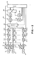
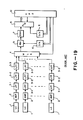
- a circuit for processing such signals in the case of a combinational weighing system with a plurality of article batch handling units is illustrated in Fig.
- weighing devices 1 such as load cells attached to weigh hoppers (not shown) output signals to associated amplifier circuits 2.
- amplifier circuits 2 Behind each of these amplifier circuits 2 is a set of three low pass filters 3-1, 3-2 and 3-3 for attenuating noise in inputted signals.
- Numeral 4 indicates a multiplexer for selectively outputting the weight signals from the individual article batch handling units; numeral 5 indicates a zero-point adjustment circuit for subtracting from the weight signals the voltage corresponding to the initial load such as the weight of the unloaded hopper; numeral 6 indicates a device for controlling the level of adjustment by the zero-point adjustment circuit 5; numeral 7 indicates a sample-and-hold circuit of a known kind; numeral 8 indicates an analog-to-digital converter; numeral 9 indicates a device for controlling a reference voltage for the analog-to-digital converter 8 for each weighing device in order to keep its span at a predetermined level; and numeral 10 indicates a computer which performs arithmetic operations for combinations of the weight values obtained from the weighing devices and selects a combination on the basis of a predetermined criterion in view of a given target weight value. Weigh hoppers associated with the combination thus selected are discharged in response to a signal outputted from this computer.
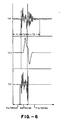
- a load cell typically forms an oscillating system and continues to oscillate, outputting a waveform as shown in Fig. 6(A) of the drawings wherein t1 represents a period in which small oscillations caused by the vibrations of the supporting frame are outputted.
- t1 represents a period in which small oscillations caused by the vibrations of the supporting frame are outputted.
- the load cell reacts as shown in the period t2.
- the oscillations in the outputted signal are attenuated gradually as shown in the period t3.
- Fig. 6(A) may be interpreted as representing a typical signal waveform when a loaded weigh hopper is discharged and immediately reloaded.
- a weight signal containing noise from various sources as shown in Fig. 6(A) is passed through a series of appropriately chosen low pass filters 3-1, 3-2 and 3-3 as shown in Fig. 19, a waveform depicted in Fig. 6(B) may be obtained with high-frequency components attenuated or effectively removed.
- a comparison between Figs. 6(A) and 6(B) shows that the signal which passed through the low pass filters takes a fairly long time to become stable. In other words, effects of a new article batch dropped into a weigh hopper remain for a long time and hence an analog signal indicative of, or proportional to the true weight value does not become available for a long time.
- a signal processing circuit for a weighing system comprising an amplifier circuit for amplifying a weight signal outputted from a weighing device, and an active filter which serves to attenuate noise components in said weight signal, characterised by switching means for selectably switching between a filter mode of operation wherein said active filter functions as a filter and a buffer mode of operation wherein said active filter functions as a buffer.
- the present invention provides a signal processing circuit for a weighing system, which reduces the delay in repsonse without adversely affecting the functions of the filter used.
- a combinational weighing system includes a number (typically 10 to 14) of article batch handling units arranged either in a circular formation around an article dispersing table or in a linear array. Articles to be weighed are typically transported by a conveyor belt and dropped into an article feeding unit from which article batches are delivered to the individual article batch handling units.
- Each article batch handling unit typically includes a pool hopper which serves to receive an article batch and discharge it into a weigh hopper belonging to the same article batch handling unit.
- the weigh hopper is connected to a weighing device 11 such as a load cell of a known type and serves to momentarily hold the article batch received from the pool hopper and discharge it in response to a signal.
- Each weighing device 11 outputs an analog weight value signal indicative of the weighed value measured thereby.
- the weight value signal is inputted to self-check circuit 12 and an operational amplifier circuit 13.
- the operational amplifier circuit 13 serves to add and amplify the output signal from the self-check circuit 12 and the weight value signal from the weighing device 11.
- the output end of the operational amplifier circuit 13 is connected to an active filter 14 which consists of three low pass filters 14-1, 14-2 and 14-3 connected in series and serves to perform selectably a filtering funtion or a buffering function as will be explained in detail below.
- the output from the active filter 14 is inputted to a zero-point adjustment circuit 15 belonging to the same article batch handling unit for subtracting the initial (zero load) weight value of the associated weigh hopper.
- Numeral 16 indicates a digital-to-analog converter for controlling the level of zero-point adjustment to be explained below.
- the output from the zero-point adjustment circuit 15 is inputted through an analong-to-digital converter 17A to a weight-monitoring computer 18 associated with the same article batch handling unit.
- Each weight-monitoring computer 18 is connected to a main computer 19 which controls the operation of the entire system including the performance of combinational computations.
- Various input and output devices such as a keyboard, a printer and a display means as well as a packaging unit to be used in combination with the system and driving control computers for controlling the opening and closing of the hopper gates are typically connected to this main computer 19, but they are not shown in Figs. 1 and 2 in order not to overly complicate the diagrams.
- the outputs from the active filters 14 of all article batch handling units are sequentially transmitted through a multiplexer 23 to a single zero-point adjustment circuit 15.
- the output from this zero-point adjustement circuit is inputted through a sample-and-hold circuit 24 of a known kind and an analog-to-digital converter 17B to the main computer 19.
- each signal processing circuit is controlled by the associated weight-monitoring computer 18 in the system of Fig. 1 while all signal processing circuits are controlled by the main computer in the system of Fig. 2.
- Fig. 3 is an example of circuit diagram for the aforementioned self-check circuit 12, amplifier circuit 13, active filter 14, etc.
- the self-check circuit 12 is adapted to function selectably either in a measurement mode or in a self-check mode.
- a low-level self-check signal SC is inputted from the computer 18 so as to close switches SW1 and to open switches SW2.
- a voltage V0 which is equal to the voltage inputted to the self-check circuit 12 is outputted from the adder AD.
- the self-check signal SC is at a high level so as to open the switches SW1 and to close the switches SW2.
- a sum of V0 and a fixed voltage proportional to a standard weight for testing is outputted from the adder AD.
- the operational amplifier circuit 13 comprises an operational amplifier which, having the bridge resisters of the load cell 11 as its input resister, serves to add the outputs from the load cell 11 and the self-check circuit 12 at its inverter input terminal.
- the current addition performed at the inverter input terminal is between the output from the self-check circuit 12 and the output terminal voltage V0 of the load cell 11 which are substantially the same, and differential amplification is effected by the operational amplifier circuit 13 such that only a weight signal proportional to the output from the load cell 11 is outputted from its output terminal.
- the self-check mode of operation the sum of the aforementioned input voltage V0 and a prefixed voltage is outputted from the self-check circuit 12, and the addition between this output voltage and the output terminal voltage of the load cell 11 (the aforementioned input voltage V0) is performed at the inverter input terminal of the operational amplifier circuit 13, followed by differential amplification such that the sum of the weight signal proportional to the output from the load cell 11 and the voltage corresponding to the standard weight generated by the self-check circuit 12 and amplified by the operational amplifier circuit 13 is outputted.
- a buffer amplifier voltage follower
- the resisters R i and the capacitors C i and C' i are so selected that the first low pass filter 14-1 will have a quick response and steep cutoff frequency characteristics, that the second low pass filter 14-2 will have a slow response and gradual cutoff frequency characteristics, and that the third low pass filter 14-3 will have intermediate characteristics.
- the switches SW are adapted to be controlled by a signal S outputted from the corresponding weight-monitoring computer 18 or by the main computer 19 such that they will be closed when the signal S is at the high level and the low pass filters 14-i funtion as filters but that they will be open when the signal S is at the low level and the low pass filters 14-1 function as a three-stage buffer (voltage follower).
- the signal which is outputted from the active filter 14 is inputted through a zero-point adjustment circuit 15 to an analog-to-digital converter 17A of a double integrater type as shown in Fig. 3 in the case of a system shown in Fig. 1,
- the output from the active filter 14 is inputted to an analog-to-digital converter 17B of a successive comparison type through a multiplexer 23, a zero-point adjustment circuit 15 and a sample-and-hold circuit 24 for all article batch handling units.
- the zero-point adjustment circuit 15 comprises an operational amplifier and the currents outputted from the third low pass filter 14-3 and the digital-to-analog coverter 16 for controlling the zero-adjustment level are added at its inverter input terminal.
- the analog-to-digital converter 17A of the double integrater type shown in Figs. 1 and 3 is so structured that its integration time can be freely changed by a soft-timer of the weight-monitoring computer 18 and span adjustments of weighing devices are effected by adjusting its integration time by the computer 18.
- span adjustments of individual weighing devices are effected by adjusting the reference voltage of the analog-to-digital converter 17B by a digital-to-analog converter 25 for span adjustment.
- each weight-monitoring computer 18 of Fig. 1 is programmed not only to read the outputs from the associated analog-to-digital converter 17A at a prefixed frequency and to determine whether the corresponding weighing device is loaded or not and whether it has stabilized or not, but also to perform zero-point and span adjustments in response to a command from the main computer 19.
- the main computer 19 of Fig. 2 is programmed not only to read the weight data from the individual weighing devices but also to perform zero-point and span adjustments, combinational computation and control of mechanisms for driving the hoppers.
- Fig. 3 is intended to be interpreted as showing only one example of the circuit structure embodying the present invention.
- the self-check circuit 12 of Fig. 3 may be replaced by a simple circuit shown in Fig. 4 and the amplifier circuit 13 of Fig. 3 may be replaced by a differential amplifier of a high input impedance type shown in Fig. 5.
- each weight-monitoring computer 18 or the main computer 19 is maintained at a high level such that the switches SW in the active filter 14 are closed.
- each weighing device 11 associated with a weigh hopper which has just received an article batch outputs a weight signal indicative of the sum of the initial weight of the hopper and the weight of the received article batch.
- This weight signal is inputted to the active filter 14 after amplified by the operational amplifier circuit 13, and its noise components caused by the vibrations of the weigh hopper, etc. are attenuated.
- the signal is then inputted, either directly or through a multiplexer 23, to the zero-point adjustment circuit 15 where a weight signal corresponding to the aforementioned initial weight is subtracted.
- the main computer 19 When a certain combination is selected according to a predetermined criterion, the main computer 19 outputs driving signals, either directly or through driver control computers belonging to the individual article batch handling units, to cause the selected weigh hoppers to discharge their contents.
- a low-level control signal S is outputted from the computer 18 or 19 to the active filter 14 either immediately before or immediately after the aforementioned driving signals are transmitted to the article batch handling units such that all switches SW of the filters 14 are opened together immediately before the weigh hopper gates are opened.
- the filters 14 are thereby switched to function as buffers and the voltages between the terminals of the capacitors C i and C' i are maintained at the values before the weigh hopper gates were opened and the article batches were discharged.
- the low-level control signal S is switched to a high level when the weigh hopper gates are closed and new article batches are dropped thereinto from the corresponding pool hoppers thereabove or when the reloading of these weigh hoppers has been completed.
- This causes all the switches SW to close together and the filters 14-i begin to function as filters again.
- the terminals of the capacitors C i and C' i are all maintained at the voltage levels before the weigh hoppers were opened and their article batches were discharged.
- the voltage changes in the capacitors C i and C' i are extremely small when the circuits are commanded to function as filters and this has the desirable effect of significantly reducing the response time required to stabilize the outputs.
- the interval between times when article batches begin to be loaded to weigh hoppers and when weight data are read can be shortened and the speed of measurement is improved correspondingly.
- the combinational weighing system is so programmed that self-check of each analog signal processing system from the operational amplifier circuit 13 to the analog-to-digital converter 17A or 17B is carried out at an appropriate interval.
- self-check of each analog signal processing system from the operational amplifier circuit 13 to the analog-to-digital converter 17A or 17B is carried out at an appropriate interval.
- one of the weigh hoppers is selected for self-check from the combination which has just been selected to discharge article batches and the pool hopper corresponding to the weigh hopper thus selected is prohibited from discharging, or supplying a new article batch into this selected weigh hopper.
- the control signal S is then switched from the low level to a high level as described above in the case of the measurement mode when the gates of the remaining weigh hoppers (other than the selected one) are closed to receive new article batches from the corresponding pool hoppers above or when the reloading of the new article batches had been completed.
- a high-level self-check signal SC is transmitted from the weight-monitoring computer 18 or the main computer 19 to the self-check circuit 12 of the article batch handling unit selected for self-check.
- the switches SW1 to open and the switches SW2 to close such that a specified voltage is outputted from the self-check circuit 12 and is added to the ouput voltage V0 from the load cell 11 at the inverter input terminal of the operational amplifier circuit 13.
- the output from the operational amplifier circuit 13 is the sum of a voltage corresponding to the initial weight of the hopper and a voltage corresponding to the standard weight.
- the zero-point adjustment circuit 15, etc. it becomes adjusted to the voltage corresponding to the standard weight, converted into a digital value by the analog-to-digital converter 17A or 17B and received by the weight-monitoring computer 18 or the main computer 19.
- the inputted value is compared with a standard value corresponding to the standard weight and, if this difference is within a predetermined allowable limit, the analog signal processing system is considered normal. If the difference is outside this allowable limit, on the other hand, the span is considered incorrect and a recovery procedure is undertaken immediately.
- the weight-monitoring computer 18 adjusts the integration time such that the output from the analog-to-digital converter 17A in the self-check mode will become the same as the aforementioned reference value.
- the digital-to-analog converter 25 is used to adjust the reference voltage such that the output from the analog-to-digital converter 17B and the aforementioned reference value will become equal.
- Self-check or a combination of self-check and span adjustment is completed before the beginning of the next cycle when new article batches are thrown into weigh hoppers and the self-check signal SC is immediately switched to a low level, the self-check circuit 12 becoming switched for a measurement mode of operation. Since the switching controls on the active filter 14 are performed also in the case of a self-check, the response stabilizes equally quickly when a test voltage is outputted from the self-check circuit 12. This means that self-check can be effected on a selected weighing device between normal cycles of weighing without affecting its speed adversely.
- the active filters need not be of a three-stage structure.
- the number of stages may be one, two or four.
- many different circuit structures may be considered according to desired characteristics.
- signal processing circuits as described may be incorporated not only in a combinational weighing system but also in an ordinary automatic weighing system.
- Fig. 6(c) is a waveform diagram for an output signal from the active filter, showing the waveform quickly stabilizing after the switching of the filters' functions at time t0.
- a signal processing circuit addressed to the problem of drifts in output signals which are inevitably caused by variations in the source voltage, temperature, etc.
- drifts cause errors in measured weight values and a common procedure of preventing such errors has been to store the output value from an analog-to-digital converter under a no-load condition as its zero-point and to calculate a net weight by retrieving this stored zero point value whenever a weight of an object is to be measured.
- Such measurements of a zero point are performed fairly frequently in order to keep updating the zero point value.
- each weight hopper remains empty only for very brief periods of time.
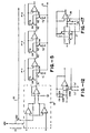
- FIG. 7 there is shown an example of signal processing circuit which may be incorporated in combinational weighing systems of Figs. 1 and 2 with only minor modifications. Parts corresponding to those in Fig. 3 are therefore indicated by the same numerals.
- numeral 14 therein again indicates an active filter having three low pass filters 14-i connected in series.
- the output signal from each weighing device 11 is inputted through a first switching means 31 to an operational amplifier circuit 32 and a reference voltage outputting circuit 33 and the output from the reference voltage outputting circuit 33 is also inputted to the operational amplifier circuit 32.
- the output from the operational amplifier circuit 32 is inputted to the active filter 14.
- the first switching means 31 is adapted to function selectably in a measurement mode or an adjustment mode of operation and is connected on the input side of an operational amplifier circuit 33.
- the first switching means In the measurement mode of operation, the first switching means outputs the output signal from the weighing device 11 and in the adjustment mode of operation, it outputs either a reference signal for detecting the magnitude of offset or a reference signal for carrying out span adjustment.
- the first switching means 31 includes normally closed switches SW11 and SW13 and normally open switches SW12 and SW14. The switches SW11 are respectively inserted between an output terminal of the weighing device 11 and the input terminal of the operational amplifier circuit 33.
- the switch SW13 is inserted through a buffer amplifier 35 between the two input terminals of one of non-inverter amplifiers 36 in the operational amplifer circuit 32.
- the switches SW12 are respectively inserted between the ground and the input terminals of the aforementioned operational amplifier circuit 32.
- the switch SW14 is inserted between the voltage dividing point of a voltage dividing circuit D for outputting a reference voltage for span check and the inverter terminal of the aforementioned non-inverter amplifier 36.
- control signals Sig1 and Sig2 are outputted from the weight-monitoring computer 18 to keep the normally closed switches SW11 and SW13 in closed conditions and the normally open switches SW12 and SW14 in open conditions such that the output from the associated weighing device 11 is inputted to the operational amplifier circuit 32 and to the buffer amplifier 35.
- the output voltage from the buffer amplifier 35 becomes equal to its input voltage and, since the voltages at both input terminals of the non-inverter amplifier 36 become equal due to imaginary short-circuiting, there is substantially no current addition at the inverter terminal of the non-inverter amplifier 36.
- the output from the weighing device 11 is amplified.
- control signals Sig1 and Sig2 from the weight-monitoring computer 18 cause the normally closed switches SW11 to open and the switches SW12 and SW13 to close, setting the input terminals of the operational amplifier circuit 32 and the input terminals of the buffer amplifier 35 at a ground level.
- an offset voltage is outputted from the signal processing circuit and the computer 18 can perform drift adjustment by monitoring its temporal variations as will be explained below.
- the active filter 14 was already described above in connection with Fig. 3.
- the control signal indicated by letter S in Fig. 3 is indicated here by three signal lines Sig3 to show that control signals to individual low pass filters 14-i may be transmitted independently.
- the two switches SW in each low pass filter 14-i will be referred to as a second switching means.
- the active filter 14 functions as a buffer (with three stages) if the switches SW (or the second switching means) are opened and as a filter if the switches SW are closed.
- the individual circuits in Fig. 7 need not be structured exactly as shown therein.
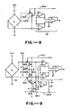
- the operational amplifier circuit 32 of Fig. 7 has the property that its offset voltage changes if its input voltage varies. Thus, the input voltage must be approximately the same as the output voltage from the load cell in the measurement mode. In order to obviate this requirement, a portion of Fig. 7 including the circuit 32 may be changed as shown in Fig. 8 or Fig. 9 in which the same numerals as defined above indicate like or corresponding components.
- the switch SW01 is closed and the switch SW02 is opened in the measurement mode of operation such that the potential difference between the two oputput terminals of the load cell 11 (bridge circuit) is calculated, amplified and outputted by the operational amplifier circuit 32.
- the switch SW01 is opened and the switch SW02 is closed such that the input voltage of the operational amplifier circuit 32 becomes nearly the same as the load cell output voltage. Since the two input voltages to the operational amplifier circuit 32 are thus nearly equal to each other, the difference calculated by it becomes zero and its output terminal outputs a drift voltage corresponding to the drift of the operational amplifier circuit 32 in the measurement mode of operation.
- the switch SW01 and SW14 are opened and the switches SW02 and SW14 are opened such that the operational amplifier circuit 32 operates as explained by way of Fig. 8.
- the switches SW01 and SW14 are opened and the switches SW02 and SW13 are closed such that a voltage (V ex /2) nearly equal to the output voltage from the load cell 11 is inputted to the oeprational amplifier circuit 32.
- a drift voltage corresponding to the drift of the oeprational amplifier circuit 32 in the meausurement mode of operation is outputted from its outpur terminal.
- the switches SW01 and SW13 are opened and the switches SW02 and SW14 are cloased such that the voltage at the non-inverter terminal of the operational amplifier circuit 32 becomes V EX /2 while a voltage given by R2 V EX /(RF1 + (R2)) is outputted fom the aforementioned voltage dividing circuit D.
- R1 and R2 are the resistances of the resisers therein as indicated in Fig. 9.
- a contstant spa-checkc voltage is outputted from the operational amplifier circuit 32.
- the operational amplifier circuit 32 of Fig. 7 with a differential amplifier of high input impedance type may be replaced by a different amplifier circuit shown by numeral 42 of Fig. 8 or numeral 52 of Fig. 9.
- These amplifier circuits 42 and 52 include an operational amplifier 46 and 56, respectively, both having as input resistor the bridge resistors of the weighing device 11.
- Numerals 41 and 51, respectively of Figs. 10 and 11, indicate first switching means according to different embodiments. According to the embodiment shown in Fig.
- the first switching means 41 includes normally closed switches SW41 inserted between the weighing device 11 and the operational amplifier 46, normally open switch SW42 inserted between the non-inverter terminal of the operational amplifier 46 and the ground, another normally open switch SW42' inserted in the feedback circuit of the operational amplifier 46, and a normally closed switch SW43 and a normally open switch SW44 which are inserted in parallel between the voltage dividing points of a voltage dividing circuit D' adapted to output two kinds of reference voltages and the output terminal of the operational amplifier 46.
- normally closed switches SW41 inserted between the weighing device 11 and the operational amplifier 46
- normally open switch SW42 inserted between the non-inverter terminal of the operational amplifier 46 and the ground
- another normally open switch SW42' inserted in the feedback circuit of the operational amplifier 46
- a normally closed switch SW43 and a normally open switch SW44 which are inserted in parallel between the voltage dividing points of a voltage dividing circuit D' adapted to output two kinds of reference voltages and the output terminal of the operational amplifier 46.
- the first switching means 51 includes normally closed switches SW51 inserted between the weighing device 11 and the operational amplifier 56, a normally open switch SW52 inserted between the non-inverter terminal of this operational amplifier 56 and the ground, and a normally open switch SW52' inserted in the feedback circuit of the operational amplifier 56.
- the switches SW41 and SW43' are closed and the switches SW42, SW42' and SW44 are opened by control signals Sig1 and Sig2 from the computer 18 such that only the output from the weighing device 11 is inputted to the operational amplifier 46.
- the switches SW41 are opened and the switches SW42 and SW42' are closed by the control signal Sig1.
- the switch SW43' is closed and the switch SW44 is opened by the control signal Sig2 such that the buffer amplifier 35 outputs a bias voltage for maintaining the input level of the analog-to-digital converter 17A somewhat on the positive side.
- the operation of the circuit of Fig. 10 is similarly explained.
- the operational amplifiers 46 and 56 of Figs. 10 and 11 function each as an inverter amplifier having a set bias voltage as input and the offset voltage generated by it is amplified and outputted.
- the offset voltage is also simultaneously outputted from the signal processing circuit.
- the ratio of amplification in this case is set equal to the amplification of the operational amplifier 46 in the measurement mode of operation such that the total offset voltage can be detected equivalently.
- the aforementioned offset is measured first and then the switches SW41 and SW43' of Fig. 10 are opened and the switches SW42, SW42' and SW44 are closed.
- a reference voltage for span adjustment is thereby outputted from the buffer amplifier 35 and a corresponding reference voltage is outputted from the operational amplifier 46 for span adjustment.
- the circuit shown in Fig. 11 is characterized as having a self-check circuit 12 in place of the reference voltage outputting circuit (33 of Fig. 7).
- the structure and function of this self-check circuit 12 are the same as explained in connection with Fig. 3.
- the main computer 19 through the weight-monitoring computer 18 related to the same article batch handling unit, causes the weigh hopper corresponding to the specified weighing device to discharge its article batch and at the same time outputs control signals Sig1, Sig2 and Sig3 to the first switching means 31 and the active filter 14 (or to the second switching means therein) to set the former in the measurement mode of operation and the latter in the filter mode of operation.
- a weight signal indicative of the weight detected by the weighing device of interest is outputted to the computer 18 which operates the digital-to-analog converter 16 to adjust the output from the analog-to-digital converter 17A to a near-zero value on the positive side, storing this value as the zero point.
- the computer 18 outputs control signals Sig1, Sig2 and Sig3 to set the first switching means 31 in the drift adjustment mode of operation and the active filter 14 (or the second switching means therein) in the buffer mode of operation.
- the input to the operational amplifier circuit 32 is thereby set at the gound level and the offset voltage of the entire system is outputted without delay, converted into a digital value and stored.
- a standard weight is placed in the weigh hopper of interest after its zero point is adjusted and a span adjustment command is inputted as in the case of zero-point adjustment described above.
- the computer 18 then outputs control signals Sig1, Sig2 and Sig3 to the first switching means 31 and to the active filter 14 (or the second switching means therein) to set the first switching means 31 in the measurement mode of operation and the active filter 14 in the filter mode of operation, causing a digital value corresponding to the standard weight to be outputted from the analog-to-digital converter 17A.
- the computer 18 inputs this digital value, obtains the span from the difference between this and the aforementioned zero-point and adjusts the span to a desired value by controlling the integration time of the analog-to-digital converter 17A.
- the computer 18 outputs control signals Sig1, Sig2 and Sig3 to the first switching means 31 and the active filter 14 (or the second switching means therein) to set the former in the offset detection mode and the latter in the buffer mode of operation, detecting an offset value from the signal processing circuit.
- control sinals Sig1 and Sig2 are outputted to the first switching means 31 without effecting any change to the active filter 14, thereby switching the first switching means 31 into the span adjustment mode of operation.
- a fixed reference voltage independent of the standard weight is outputted from the operational amplification circuit 32 and is converted into a digital value by the analog-to-digital converter 17A and inputted to the computer 18 without a delay.
- the computer 18 calculates a span value based on this digital value and the aforementioned offset value when the reference voltage is inputted. This calculated value is then stored as the reference value when there is no error in the span. Thereafter, the operation of the system is resumed, with span adjustment mode of operation repeated as explained above.
- the span check and drift check are both effected through a buffer circuit involving no delay in response, they can be completed instantaneously without disturbing the cyclic operation of combinational weighing.
- signal processing circuits of the second embodiment of the present invention were explained as parts of a combinational weighing system of the type having weight-monitoring computers for the individual article batch handling units in addition to the main computer for controlling the operation of the entire system, or the type illustrated by Fig. 1.
- These signal processing circuits can be incorporated equally well in the type of combinational weighing systems illustrated by Fig. 2.
- the functions performed by the weight-monitoring computer 18 in the example explained above must be performed by the main computer 19.
- the signal processing circuits of this embodiment can be used in many types of weighing systems.
- the filter shown by Fig. 12 is characteristic in that its response characteristics can be switched between fast and low by means of switches SW7 and SW8.
- the filter When the filter is set for the buffer mode of operation, such low pass filter might be set for smaller delay in response such that high frequency components of the signal will be attenuated.
- the characteristic frequency of the weighing device When the characteristic frequency of the weighing device is included in the signal, the signal level may cease to be constant when a change is effected from adjustment mode of operation to measurement mode of operation. This can cause fluctuations in the rise times of weight signals when articles to be weighed are dropped in, thus randomizing the stabilization time of measurement.
- Fig. 13 is a circuit diagram of an active filter which includes in view of the above a notch filter 26 for attenuating the noise caused by the free oscillations of the weighing device.
- Such an active filter can take the place of active filters shown, for example, in Figs.
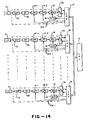
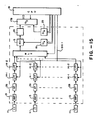
- Figs. 14 and 15 wherein components corresponding to those in Figs. 1, 2 and 7 are indicated by the same numerals.
- Fig. 14 is a system of the type shown in Fig.1, having a weight-monitoring computer 18 for each of its article batch handling unit.
- Fig. 15 is a system of the type shown in Fig. 2, having a mulitplexer to input weight signals from the individual article batch handling units sequentially into the main computer 19 which also performs the functions of weight-monitoring computers 18 of Fig. 14.
- Structures and functions of the components shown in Figs. 12 and 13 other than those shown in Fig. 13 were already explained above in connection with Figs. 1 and 2 and hence will not be explained below.
- the notch filter 26 is inserted between an amplifier circuit 13 and low pass filters 14-1 and 14-2 connected in series. It includes a twin-T circuit 27 of a well known type having resistors and capacitors and the output end of this twin-T circuit 27 is connected to a buffer amplifier 28 through a parallel RC circuit 29 for impedance matching. Its filter constant is adjusted for the attenuation of the components corresponding to the characteristic oscillation of the weighing device including the associated weigh hopper. Signal noise with large amplitudes is thereby attenuated quickly in the free oscillation period after the weigh hopper gate is released from external forces.
- the middle point of resistors Rj of the RC integrated circuit Ij is connected to the inverter terminal of the buffer amplifier 30 through a switch SW7j and a capacitor Cj, and a switch SW7j' is inserted between a capacitor C'j belonging to the RC intergrator circuit Ij and the non-inverter terminal of the buffer amplifier 30.
- control signal Sig1 is outputted from the computer 18 or 19 to open the switches SW7j and SW7j' such that the low pass filters 14-1 and 14-2 are simultaneously made to function as buffers.
- the computer 18 or 19 outputs another control signal Sig1 when a new article batch is expected to have been received to close these switches SW7j and SW7j' such that the low pass filter 14-1 and 14-2 are simultaneously made to function as filters.
- the resistors and capacitors of the low pass filters are so selected that the first low pass filter 14-1 will respond quickly and the cutoff frequency characteristic is steep while the second low pass filter 14-2 will have a slow response and its cutoff frequency characteristic is gently sloped.
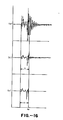
- each weighing device 11 (with reference, for example, to Figs. 14 and 15) outputs during one cycle of the system's operation a signal which includes components with large amplitudes corresponding to the characteristic oscillation of the weighing device as shown in Fig. 16(a).
- this signal is passed through the notch filter 26, these characteristic oscillations are attenuated as shown in Fig. 16(b).
- the delay in response of the weight signal which is the direct current component is small in the notch filter 26. Only the characteristic oscillation components with large amplitudes are attenuated.
- the low pass filters 14-1 and 14-2 are set to function as buffers.
- the signal containing noise is directly outputted through the low pass filters 14-1 and 14-2.
- a control signal Sig1 from the computer 18 or 19 causes the low pass filters 14-1 and 14-2 to start functioning as filters.
- the components corresponding to the characteristic oscillations which have already been attenuated by the notch filter 26 are further attenuated by the low pass filters 14-1 and 14-2.
- the weight signal stabilizes very quickly after the time t0 as shown in Fig. 16(c) converging to the final weight value.
- weight signals obtained as explained above are successively sampled at a predetermined frequency inclusive of the period before stability is established. These inputted values are converted into digital values and inputted and stored by the individual weight-monitoring computers 18.
- detected weights of the individual weighing devices are successively sampled when the weight signals are considered stabilized, and they are converted into digital values and sequentially inputted to the main computer 19.
- the notch filter 26 of Fig. 13 may be structured as shown in Fig. 17 such that it, too, can be selectably made to function as a buffer or as a filter. With a notch filter of this type, drift corrections and span adjustments described above in connection with the system of Fig. 7 can also be performed.
- the notch filter of Fig.17 is intended to be used first as a filter to attenuate the noise components with large amplitudes and then the low pass filters 14-1 and 14-2 are switched from the buffer mode to the filter mode of operation.
- a plurality of notch filters with different cutoff frequency values may be used and these switchable filters may be switched from one mode of operation to another either simultaneously or successively.
- the zero-point adjustment circuit 15 may be inserted between the amplifier circuit 32 and the notch filter 26 and the amplifier circuit 32 itself may be structured to function as a zero-point adjustment circuit.
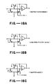
- the notch filter of Fig. 17 may be replaced by another shown in Fig. 18 which can be operated in the notch filter mode as shown in Fig. 18(a), the low pass filter mode as shown in Fig. 18(b) and the buffer mode as shown in Fig. 18(c).
- the filter shown in Fig. 18 is advantageous furthermore because the number of components is small and hence it is less expensive. It does not require a precision resistor and the attenuation bandwidths cannot be freely adjusted.
- a signal processing circuit is characterized as having a notch filter behind an amplifier circuit such that the components corresponding to the characteristic oscillation of the associated weighing device with large amplitudes are attenuated.
- the output from this notch filter is inputted to low pass filters which can be selectably made to function either as filters or as buffers such that they serve as filters after an article batch is thrown into the associated hopper.
- Weight signals can be stabilized much more quickly and the overall efficiency of the weighing system can be improved.
- the notch filter effectively attenuates the noise components with largest amplitudes but transmits other signal noise components without delay in response, it can serve as an effective noise filter against signal noise with large amplitudes caused by the free oscillation of the weighing device and, if coupled with low pass filters as shown above, it can efficiently utilize its high-speed and quick-attenuating characteristics.
Landscapes
- Physics & Mathematics (AREA)
- General Physics & Mathematics (AREA)
- Indication And Recording Devices For Special Purposes And Tariff Metering Devices (AREA)
- Analogue/Digital Conversion (AREA)
- Weight Measurement For Supplying Or Discharging Of Specified Amounts Of Material (AREA)
Applications Claiming Priority (6)
| Application Number | Priority Date | Filing Date | Title |
|---|---|---|---|
| JP21056585A JPS6269125A (ja) | 1985-09-24 | 1985-09-24 | 計量装置の信号処理回路 |
| JP210565/85 | 1985-09-24 | ||
| JP258379/85 | 1985-11-18 | ||
| JP60258379A JPS62118219A (ja) | 1985-11-18 | 1985-11-18 | 計量装置 |
| JP29874685A JPS62156528A (ja) | 1985-12-27 | 1985-12-27 | 計量装置の信号処理回路 |
| JP298746/85 | 1985-12-27 |
Publications (3)
| Publication Number | Publication Date |
|---|---|
| EP0216638A2 true EP0216638A2 (fr) | 1987-04-01 |
| EP0216638A3 EP0216638A3 (en) | 1988-06-22 |
| EP0216638B1 EP0216638B1 (fr) | 1990-04-25 |
Family
ID=27329137
Family Applications (1)
| Application Number | Title | Priority Date | Filing Date |
|---|---|---|---|
| EP86307338A Expired EP0216638B1 (fr) | 1985-09-24 | 1986-09-24 | Système de pesage et circuit à cet effet |
Country Status (5)
| Country | Link |
|---|---|
| US (1) | US4705126A (fr) |
| EP (1) | EP0216638B1 (fr) |
| AU (1) | AU588177B2 (fr) |
| CA (1) | CA1256905A (fr) |
| DE (1) | DE3670690D1 (fr) |
Cited By (6)
| Publication number | Priority date | Publication date | Assignee | Title |
|---|---|---|---|---|
| EP0418567A1 (fr) * | 1989-08-25 | 1991-03-27 | Tokyo Electric Co., Ltd. | Dispositif pour mesurer une force, en particulier une charge |
| EP0429725A1 (fr) * | 1989-11-29 | 1991-06-05 | Yamato Scale Company, Limited | Dispositif et méthode pour filtrer un signal de poids provenant d'un systÀ¨me de pesée |
| US5210706A (en) * | 1989-08-25 | 1993-05-11 | Tokyo Electric Co. Ltd. | Device for measuring a physical force |
| EP0590153A4 (fr) * | 1992-02-28 | 1994-05-04 | Ishida Co., Ltd. | |
| EP0604756A1 (fr) * | 1992-12-29 | 1994-07-06 | Pietzsch Automatisierungstechnik Gmbh | Interface pour balances électromécaniques étalonnées |
| US5656800A (en) * | 1992-02-28 | 1997-08-12 | Ishida Co., Ltd. | Accurate and responsive weighing apparatus with drift compensation |
Families Citing this family (15)
| Publication number | Priority date | Publication date | Assignee | Title |
|---|---|---|---|---|
| EP0122796B1 (fr) * | 1983-04-14 | 1989-08-02 | Kabushiki Kaisha Ishida Koki Seisakusho | Balance |
| JPH0621814B2 (ja) * | 1986-05-29 | 1994-03-23 | 大和製衡株式会社 | 計重装置の計重信号の濾波方法及び装置 |
| EP0357616B1 (fr) * | 1988-03-15 | 1994-05-25 | Keller AG für Druckmesstechnik | Procede et dispositif pour la compensation des erreurs de mesure |
| US5756938A (en) * | 1990-01-25 | 1998-05-26 | Ishida Scales Mfg. Co., Ltd. | Weight measuring apparatus |
| US5029658A (en) * | 1990-04-12 | 1991-07-09 | Clintec Nutrition Co. | Mass/weight measurement filtering system |
| JPH0656315B2 (ja) * | 1990-07-24 | 1994-07-27 | 株式会社イシダ | 重量測定装置 |
| US5936206A (en) * | 1993-12-31 | 1999-08-10 | Ishida Co., Ltd. | Weighing machines with means for correcting effects of floor vibrations on weight signals therefrom |
| US6034334A (en) * | 1994-04-12 | 2000-03-07 | Ishida Co. Ltd. | Method of and means for correcting effects of floor vibrations on weight signals from a weighing machine |
| JPH11108751A (ja) * | 1997-10-08 | 1999-04-23 | Ishida Co Ltd | フィルタ自動調整機能付き計量装置 |
| US7114368B2 (en) * | 2003-04-08 | 2006-10-03 | Abbott Laboratories | Apparatus and method for verifying the volume of liquid dispensed by a liquid-dispensing mechanism |
| EP1736748B1 (fr) | 2005-06-21 | 2012-05-02 | Mettler-Toledo AG | Procédé de traitement du signal de sortie d'un capteur de mesure et dispositif de mesure de force servant à la mise en oeuvre de ce procédé. |
| DE102006041836B4 (de) * | 2006-09-04 | 2009-04-02 | Wipotec Wiege- Und Positioniersysteme Gmbh | Wägevorrichtung, insbesondere Wägezelle für eine Verbundwaage |
| CN104748831B (zh) * | 2015-03-23 | 2017-08-25 | 沈阳新一代信息技术有限公司 | 一种称重传感器多量程毫伏信号转换装置及方法 |
| CN108801406A (zh) * | 2018-05-15 | 2018-11-13 | 常州百擎智能工程有限公司 | 防爆信号隔离电路及其工作方法 |
| JP7585640B2 (ja) * | 2020-07-21 | 2024-11-19 | セイコーエプソン株式会社 | 信号処理方法及び信号処理装置 |
Family Cites Families (9)
| Publication number | Priority date | Publication date | Assignee | Title |
|---|---|---|---|---|
| US3692129A (en) * | 1971-04-12 | 1972-09-19 | Howe Richardson Scale Co | Load cell weighing systems |
| US4139069A (en) * | 1977-06-23 | 1979-02-13 | Acurex Corporation | Digital weighing method |
| JPS5753627A (en) * | 1980-09-17 | 1982-03-30 | Ishida Scales Mfg Co Ltd | Zero-point adjusting method of combinational metering device or combinational counting device |
| US4633425A (en) * | 1981-10-13 | 1986-12-30 | Intel Corporation | Switched capacitor filter utilizing a differential input and output circuit |
| US4535854A (en) * | 1982-11-16 | 1985-08-20 | Pennsylvania Scale Company | Calibration method and apparatus for an electronic weight indicator |
| FR2537276A1 (fr) * | 1982-12-02 | 1984-06-08 | Testut Aequitas | Dispositif electronique de mesure avec filtrage passe-bas accelere, en particulier pour le pesage |
| JPS59200923A (ja) * | 1983-04-28 | 1984-11-14 | Ishida Scales Mfg Co Ltd | スパン調整方法 |
| US4580644A (en) * | 1983-06-09 | 1986-04-08 | Tokyo Electric Co., Ltd. | Load cell type weight measuring device and a sensitivity checking method thereof |
| US4572309A (en) * | 1983-11-15 | 1986-02-25 | Tokyo Electric Co., Ltd. | Load cell type weight-measuring device |
-
1986
- 1986-09-10 US US06/905,876 patent/US4705126A/en not_active Expired - Lifetime
- 1986-09-18 AU AU62799/86A patent/AU588177B2/en not_active Ceased
- 1986-09-23 CA CA000518820A patent/CA1256905A/fr not_active Expired
- 1986-09-24 EP EP86307338A patent/EP0216638B1/fr not_active Expired
- 1986-09-24 DE DE8686307338T patent/DE3670690D1/de not_active Expired - Lifetime
Cited By (6)
| Publication number | Priority date | Publication date | Assignee | Title |
|---|---|---|---|---|
| EP0418567A1 (fr) * | 1989-08-25 | 1991-03-27 | Tokyo Electric Co., Ltd. | Dispositif pour mesurer une force, en particulier une charge |
| US5210706A (en) * | 1989-08-25 | 1993-05-11 | Tokyo Electric Co. Ltd. | Device for measuring a physical force |
| EP0429725A1 (fr) * | 1989-11-29 | 1991-06-05 | Yamato Scale Company, Limited | Dispositif et méthode pour filtrer un signal de poids provenant d'un systÀ¨me de pesée |
| EP0590153A4 (fr) * | 1992-02-28 | 1994-05-04 | Ishida Co., Ltd. | |
| US5656800A (en) * | 1992-02-28 | 1997-08-12 | Ishida Co., Ltd. | Accurate and responsive weighing apparatus with drift compensation |
| EP0604756A1 (fr) * | 1992-12-29 | 1994-07-06 | Pietzsch Automatisierungstechnik Gmbh | Interface pour balances électromécaniques étalonnées |
Also Published As
| Publication number | Publication date |
|---|---|
| AU588177B2 (en) | 1989-09-07 |
| AU6279986A (en) | 1987-03-26 |
| DE3670690D1 (de) | 1990-05-31 |
| EP0216638B1 (fr) | 1990-04-25 |
| CA1256905A (fr) | 1989-07-04 |
| US4705126A (en) | 1987-11-10 |
| EP0216638A3 (en) | 1988-06-22 |
Similar Documents
| Publication | Publication Date | Title |
|---|---|---|
| EP0216638B1 (fr) | Système de pesage et circuit à cet effet | |
| US5767455A (en) | Apparatus and method for controlling a vibratory feeder in a weighing machine | |
| US5300736A (en) | Adaptive timing in-motion checkweigher | |
| US6271484B1 (en) | Weighing apparatus having an automatic filter adjusting capability | |
| US3800893A (en) | Weighing apparatus and method | |
| KR100280900B1 (ko) | 계량 장치 | |
| US5805467A (en) | Weight measuring method using a plurality of sensors | |
| US4951763A (en) | Checkweigher | |
| EP0736754B1 (fr) | Dispositif pour charger un récipient avec des articles pesés | |
| US4751973A (en) | Load cell scale with reference channel for live load correction | |
| US4158396A (en) | Electronic weight measuring device | |
| WO1992004775A1 (fr) | Dispositif et procede ameliores de remise a zero automatique pour systeme informatise d'acquisition de donnees tomographiques | |
| US5152354A (en) | Weigh feeding apparatus for pourable substances | |
| JPH076829B2 (ja) | 計量装置 | |
| EP0622617B1 (fr) | Dispositif de pesage avec au moins trois cellules vides | |
| JPH0569173B2 (fr) | ||
| CA1050058A (fr) | Commande numerique d'alimentation pour balance | |
| JP4685217B2 (ja) | 組合せ計量機の重量測定装置 | |
| JP3465946B2 (ja) | ロードセルの温度補償方法及びその装置 | |
| JP4245230B2 (ja) | 定量供給装置 | |
| JP3251707B2 (ja) | 組合せ計量装置 | |
| JPH0569174B2 (fr) | ||
| EP0643288A1 (fr) | Procédé et dispositif pour la pesée combinatoire | |
| JPH11301833A (ja) | 電磁フィーダ、計量装置および組合せ計量システム | |
| JP3406657B2 (ja) | 組合せ計量方法およびその装置 |
Legal Events
| Date | Code | Title | Description |
|---|---|---|---|
| PUAI | Public reference made under article 153(3) epc to a published international application that has entered the european phase |
Free format text: ORIGINAL CODE: 0009012 |
|
| AK | Designated contracting states |
Kind code of ref document: A2 Designated state(s): DE FR GB SE |
|
| PUAL | Search report despatched |
Free format text: ORIGINAL CODE: 0009013 |
|
| AK | Designated contracting states |
Kind code of ref document: A3 Designated state(s): DE FR GB SE |
|
| 17P | Request for examination filed |
Effective date: 19880826 |
|
| 17Q | First examination report despatched |
Effective date: 19890418 |
|
| GRAA | (expected) grant |
Free format text: ORIGINAL CODE: 0009210 |
|
| AK | Designated contracting states |
Kind code of ref document: B1 Designated state(s): DE FR GB SE |
|
| REF | Corresponds to: |
Ref document number: 3670690 Country of ref document: DE Date of ref document: 19900531 |
|
| ET | Fr: translation filed | ||
| PLBE | No opposition filed within time limit |
Free format text: ORIGINAL CODE: 0009261 |
|
| STAA | Information on the status of an ep patent application or granted ep patent |
Free format text: STATUS: NO OPPOSITION FILED WITHIN TIME LIMIT |
|
| 26N | No opposition filed | ||
| EAL | Se: european patent in force in sweden |
Ref document number: 86307338.3 |
|
| REG | Reference to a national code |
Ref country code: GB Ref legal event code: IF02 |
|
| PGFP | Annual fee paid to national office [announced via postgrant information from national office to epo] |
Ref country code: FR Payment date: 20050823 Year of fee payment: 20 |
|
| PGFP | Annual fee paid to national office [announced via postgrant information from national office to epo] |
Ref country code: SE Payment date: 20050906 Year of fee payment: 20 |
|
| PGFP | Annual fee paid to national office [announced via postgrant information from national office to epo] |
Ref country code: GB Payment date: 20050921 Year of fee payment: 20 |
|
| PGFP | Annual fee paid to national office [announced via postgrant information from national office to epo] |
Ref country code: DE Payment date: 20050922 Year of fee payment: 20 |
|
| REG | Reference to a national code |
Ref country code: GB Ref legal event code: PE20 |
|
| PG25 | Lapsed in a contracting state [announced via postgrant information from national office to epo] |
Ref country code: GB Free format text: LAPSE BECAUSE OF EXPIRATION OF PROTECTION Effective date: 20060923 |
|
| EUG | Se: european patent has lapsed |