EP0216457A1 - Verfahren zur Herstellung von Permanentmagneten der Zweiphasen-Trennungsserie des Fe-Cr-Co-Typs - Google Patents
Verfahren zur Herstellung von Permanentmagneten der Zweiphasen-Trennungsserie des Fe-Cr-Co-Typs Download PDFInfo
- Publication number
- EP0216457A1 EP0216457A1 EP19860305484 EP86305484A EP0216457A1 EP 0216457 A1 EP0216457 A1 EP 0216457A1 EP 19860305484 EP19860305484 EP 19860305484 EP 86305484 A EP86305484 A EP 86305484A EP 0216457 A1 EP0216457 A1 EP 0216457A1
- Authority
- EP
- European Patent Office
- Prior art keywords
- tape
- annealing
- subjected
- heat treatment
- temperature
- Prior art date
- Legal status (The legal status is an assumption and is not a legal conclusion. Google has not performed a legal analysis and makes no representation as to the accuracy of the status listed.)
- Withdrawn
Links
Images


Classifications
-
- C—CHEMISTRY; METALLURGY
- C21—METALLURGY OF IRON
- C21D—MODIFYING THE PHYSICAL STRUCTURE OF FERROUS METALS; GENERAL DEVICES FOR HEAT TREATMENT OF FERROUS OR NON-FERROUS METALS OR ALLOYS; MAKING METAL MALLEABLE, e.g. BY DECARBURISATION OR TEMPERING
- C21D8/00—Modifying the physical properties by deformation combined with, or followed by, heat treatment
- C21D8/12—Modifying the physical properties by deformation combined with, or followed by, heat treatment during manufacturing of articles with special electromagnetic properties
-
- C—CHEMISTRY; METALLURGY
- C22—METALLURGY; FERROUS OR NON-FERROUS ALLOYS; TREATMENT OF ALLOYS OR NON-FERROUS METALS
- C22C—ALLOYS
- C22C38/00—Ferrous alloys, e.g. steel alloys
- C22C38/18—Ferrous alloys, e.g. steel alloys containing chromium
- C22C38/30—Ferrous alloys, e.g. steel alloys containing chromium with cobalt
-
- H—ELECTRICITY
- H01—ELECTRIC ELEMENTS
- H01F—MAGNETS; INDUCTANCES; TRANSFORMERS; SELECTION OF MATERIALS FOR THEIR MAGNETIC PROPERTIES
- H01F1/00—Magnets or magnetic bodies characterised by the magnetic materials therefor; Selection of materials for their magnetic properties
- H01F1/01—Magnets or magnetic bodies characterised by the magnetic materials therefor; Selection of materials for their magnetic properties of inorganic materials
- H01F1/03—Magnets or magnetic bodies characterised by the magnetic materials therefor; Selection of materials for their magnetic properties of inorganic materials characterised by their coercivity
- H01F1/032—Magnets or magnetic bodies characterised by the magnetic materials therefor; Selection of materials for their magnetic properties of inorganic materials characterised by their coercivity of hard-magnetic materials
- H01F1/04—Magnets or magnetic bodies characterised by the magnetic materials therefor; Selection of materials for their magnetic properties of inorganic materials characterised by their coercivity of hard-magnetic materials metals or alloys
-
- C—CHEMISTRY; METALLURGY
- C21—METALLURGY OF IRON
- C21D—MODIFYING THE PHYSICAL STRUCTURE OF FERROUS METALS; GENERAL DEVICES FOR HEAT TREATMENT OF FERROUS OR NON-FERROUS METALS OR ALLOYS; MAKING METAL MALLEABLE, e.g. BY DECARBURISATION OR TEMPERING
- C21D1/00—General methods or devices for heat treatment, e.g. annealing, hardening, quenching or tempering
- C21D1/04—General methods or devices for heat treatment, e.g. annealing, hardening, quenching or tempering with simultaneous application of supersonic waves, magnetic or electric fields
-
- C—CHEMISTRY; METALLURGY
- C21—METALLURGY OF IRON
- C21D—MODIFYING THE PHYSICAL STRUCTURE OF FERROUS METALS; GENERAL DEVICES FOR HEAT TREATMENT OF FERROUS OR NON-FERROUS METALS OR ALLOYS; MAKING METAL MALLEABLE, e.g. BY DECARBURISATION OR TEMPERING
- C21D8/00—Modifying the physical properties by deformation combined with, or followed by, heat treatment
- C21D8/12—Modifying the physical properties by deformation combined with, or followed by, heat treatment during manufacturing of articles with special electromagnetic properties
- C21D8/1205—Modifying the physical properties by deformation combined with, or followed by, heat treatment during manufacturing of articles with special electromagnetic properties involving a particular fabrication or treatment of ingot or slab
- C21D8/1211—Rapid solidification; Thin strip casting
Definitions
- This invention relates to a method of producing permanent magnets, and more particularly to a method of producing a two-phase separation type Fe-Cr-Co series permanent magnet having improved workability and magnetic properties.
- Permanent magnets are materials capable of generating a magnetic field without the supply of electrical energy trom the outside, which are usually evaluated by a maximum energy product (BH)max.
- BH maximum energy product
- Hc coercive force
- Br residual magnetic flux density
- Fig. 1 the relation among these parameters is shown in Fig. 1, from which it can be seen that the larger values of Br and Hc become better in the permanent magnet.
- Hc is a measure for magnetic force retaining Br against demagnetizing field.
- (BH)max is a maximum value on an energy product curve obtained by calculating product of B and H at a demagnetization curve in a second quadrant of Fig. 1, which means a maximum value of energy per unit volume born by the magnet.
- permanent magnets are used over wide applications for acoustic instruments, communication equipments, measuring apparatuses and electrical machines and instruments such as speaker, microphone, telephone, magnetron, klystron, microwave guide, ammeter, voltmeter, wattmeter, electric motor, generator, micrometer, hysteresis motor and so on.
- high-performance permanent magnets are poor in the workability because they are hard and brittle as in alnico magnet, ferrite magnet and rare earth series magnet. For this reason, there is a great restriction on the method of producing these permanent magnets. For instance, the production of alnico magnet is restricted to a casting process, while the production of ferrite and rare earth series magnets is restricted to a powder sintering process. For this reason, these high-performance permanent magnets are frequently shaped into blocks from a viewpoint of production restriction.
- magnets capable of shaping into a plate-like form without restricting the production method are limited to only easy-workable cunife, cunico and vicalloy magnets.
- these magnets are fairly poor in the magnetic properties as compared with the alnico, ferrite and rare earth series magnets.
- Fe-Cr-Co series alloys are described in Japanese Patent laid open No. 59-83751 are largely watched because they are rich in the workability and have an energy product (BH)max larger than that of the conventional easy-workable cunife, cunico and vicalloy magnets.
- (BH)max of the Fe-Cr-Co series alloy is still low as compared with that of the alnico and ferrite magnets, so that it is strongly demanded to further improve the properties of the Fe-Cr-Co series alloy.
- an object of the invention to advantageously solve the aforementioned problems of the prior art and to provide a method of producing two-phase separation type Fe-Cr-Co series permanent magnets having a good workability and improved magnetic properties.
- a method of producing a two-phase separation type Fe-Cr-Co series permanent magnet which comprises melting a two-phase separation type alloy of the following formula: or , wherein M is at least one element selected from the group consisting of Ti, Zr, V, Nb, Ta, Mo, B, W, AI, Cu, Si, Sn, P, Mn, Zn, Be, Hf and rare earth elements, x is 3 to 40 wt%, y is 2 to 40 wt% and z is 0.01 to 35 wt% in total, subjecting the resulting melt to a rapid solidification process to form a metallic tape or to usual ingot making-slabbing or continuous casting, hot rolling and cold rolling process to form a thin sheet, and then subjecting the resulting tape or sheet to a heat treatment within a given temperature range.
- M is at least one element selected from the group consisting of Ti, Zr, V, Nb, Ta, Mo, B, W, AI, Cu, Si, Sn, P, Mn, Zn, Be
- the Fe-Cr-Co series permanent magnets having a highly aligned ⁇ 110 ⁇ 001> orientation are produced by rolling the tape or sheet of the above alloy composition at a draft of 30-95% prior to the heat treatment and then performing the heat treatment that the rolled tape or sheet is subjected to a recrystallization annealing at a temperature of 800-1300°C, a two-phase separation annealing in a magnetic field at a temperature of 600-750°C and an age annealing at a temperature below the separation annealing temperature in this order.
- the Fe-Cr-Co series permanent magnets having a highly aligned ⁇ 100 ⁇ 011> orientation are produced by rolling the tape or sheet of the above alloy composition at a draft of not less than 40% prior to the heat treatment and then subjecting the rolled tape or sheet to an annealing inclusive of two-phase separation annealing at a temperature of 500-750°C as the heat treatment.
- the Fe-Cr-Co series permanent magnets having easy magnetization axes in radial direction of their plane are produced by subjecting the tape or sheet of the above alloy composition to a two-phase separation annealing at a temperature of 600-750°C in a magnetic field while rotating a direction of magnetic field applied to the tape or sheet in a plane parallel thereto and an age annealing at a temperature below the separation annealing temperature in this order as the heat treatment.
- the Fe-Cr-Co series permanent magnets having a highly aligned ⁇ 100 ⁇ 001> orientation are produced by subjecting the tape or hot-rolled sheet of the above alloy composition to two-stage cold rolling through an intermediate annealing at a first draft of not less than 10% and a second draft of 50-80% prior to the heat treatment and then performing the heat treatment that the rolled tape or sheet is subjected to a recrystallization annealing at a temperature of 800-1300°C and an annealing inclusive of two-phase separation annealing at a temperature of 500-750°C.
- the Fe-Cr-Co series permanent magnets having an easy magnetization axis in a direction perpendicular to plane are produced by subjecting the tape of the above alloy composition to a two-phase separation annealing in a magnetic field at a temperature of 600-750°C while applying the magnetic field in a direction perpendicular to the plane of the tape and an age annealing at a temperature below the separation annealing temperature in this -order as the heat treatment.
- Cr is an effective element for the formation of a matrix being Cr-rich nonmagnetic a 2 phase.
- the Cr amount is less than 3%, the ⁇ 2 phase is not a matrix but is a precipitation phase after the two-phase separation, while Fe-rich a i phase is a matrix, so that satisfactory properties as a permanent magnet can not be obtained.
- the spinodal decomposition temperature lowers, so that a long time is required for the two-phase separation through spinodal decomposition.
- the Cr amount exceeds 40%, Fe-Cr series a phase begins to locally precipitate in the Fe-Cr-Co series alloy and the resulting tape or sheet is very brittle and difficult in the workability.
- the spinodal decomposition temperature lowers to require a long time for two-phase separation, and also Fe-rich ⁇ 1 phase becomes smaller to degrade the properties of the permanent magnet. Therefore, the Cr amount is restricted to a range of 3-40%.
- Co effectively contribute not oily to raise the spinodal decomposition temperature of the Fe-Cr-Co series alloy for completing two-phase separation in a short time but also to raise the Curie temperature for more enhancing the effect of magnetic field applied in the spinodal decomposition.
- the Co amount is less than 2%, satisfactory treating effect in magnetic field based on the sufficient rising of spinodal decomposition temperature and Curie temperature can not be obtained.
- the Cr amount exceeds 40%, Fe and Co ordered phases are locally precipitated to degrade the workability, and the addition effect is saturated to cause the cost-up. Therefore, the Co amount is restricted to a range of 2-40%.
- M is at least one element selected from Ti, Zr, V, Nb, Ta, Mo, B, W, A2, Cu, Si, Sn, P, Mn, Zn, Be, Hf and rare earth elements, which forms a phase by reacting with Fe to prevent the enlargement of y phase loop in the Fe-Cr-Co series alloy and narrow the range of ⁇ transformation in the cooling.
- the rare earth element means to include Y, La, Ce, Pr, Nd, Pm, Sm, Eu, Gd, Tb, Dy, Ho, Er, Tm, Yb and Lu.
- single a phase is necessary to exist as a supersaturation coolant prior to spinodal decomposition because the incorporation of y phase can not give good properties as a permanent magnet.
- the amount of M is less than 0.01% in total, y phase remains during the cooling down to room temperature and the supersaturated solid solution of single a phase can not be attained, so that it is difficult to separate the single a phase into a i phase and a 2 phase through the spinodal decomposition and y phase is locally existent in the a phase to degrade the magnetic properties.
- the amount of M is restricted to a range of 0.01-35% in total.
- the melt of the aforementioned fundamental alloy composition is subjected to a rapid solidification process or to usual ingot making or continuous casting and hot and cold rollings to form a metallic tape or thin sheet having a thickness of about 0.05-5.0 mm (hereinafter referred to as a base plate).
- the thickness of the base plate is less than 0.05 mm, it is difficult to perform finish rolling, which is carried out prior to subsequent heat treatment if necessary, at a sufficient draft, while when the thickness exceeds 5.0 mm, the cracking is apt to be caused and the handling is difficult.
- the base plate is subjected to warm or cold rolling at a final draft of 30-95% so as to provide a final product thickness prior to the subsequent heat treatment.
- the final draft is less than 30%, the alignment of ⁇ 110 ⁇ 001> orientation with respect to the rolling direction after secondary recrystallization annealing as mentioned later is poor and the improved magnetic properties can not be obtained, while when it exceeds 95%, the alignment of ⁇ 110 ⁇ 001> orientation with respect to the rolling direction is insufficient and the rolling itself becomes difficult and the cost-up is caused.
- the rolled base plate is subjected to a heat treatment as mentioned below.
- the rolled base plate is subjected to recrystallization annealing at a temperature of 800-1300°C to highly align ⁇ 110 ⁇ 001> orientation with respect to the rolling direction.
- recrystallization annealing temperature is lower than 800°C, a long time is required for the recrystallization and the alignment of ⁇ 110 ⁇ 001> orientation is apt to be dispersed, while when it exceeds 1300°C, the surface of the base plate may solute depending upon the alloy composition and the disadvantages in the equipment and operation become conspicuous.
- the melt of Fe 60 -Cr 25 -Co 15 alloy was shaped into a rapidly solidified metallic tape of 0.5 mm in thickness through twin roll process, rolled at a given draft ranging from 10% to 95% and then subjected to recrystallization annealing at 1250°C for 30 minutes. Thereafter, the crystal texture of the resulting tape was examined to obtain (200) pole figures shown in Fig. 2.
- the permanent magnet material having a highly aligned ⁇ 110 ⁇ 001> orientation with respect to the rolling direction is formed at the steps of rolling ⁇ recrystallization annealing, the magnetic properties are more improved by subjecting to two-phase separation annealing in magnetic field and age annealing as the heat treatment.
- the two-phase separation annealing is to cause the so-called spinodal decomposition.
- the separation annealing temperature is lower than 600°C, a long time is uneconomically required for the spinodal decomposition, while when it exceeds 750°C, it is very difficult to separate the single a phase into a 1 and a 2 phases, and also the separation annealing temperature approaches to the Curie point of the alloy, so that the a l phase produced by the spinodal decomposition is not aligned in the direction of magnetic field when the magnetic field is applied to the alloy. Therefore, the separation annealing temperature in the magnetic field is restricted to a range of 600-750°C. In this case, the intensity of magnetic field is desired to be not less than 0.5 k0e.
- age annealing is carried out at a temperature below the separation annealing temperature, for example at a temperature below 600°C.
- This age annealing is to achieve the equilibrium state in each of a i and ⁇ 2 phases separated by the spinodal decomposition and provide nonmagnetization of a 2 phase (M-rich phase) at room temperature.
- the resulting a 2 phase exhibits a strong magnetism at room temperature and the difference in magnetization intensity between ⁇ 1 phase (Fe-rich phase) and a 2 phase, resulting in the decrease of coercive force represented by Hc « (Is Fe -Is M ).
- C produces a Cottrell effect by acting with dislocation introduced during the rolling to cause the locking or tangling of dislocation, resulting in the increase of dislocation density for promoting the formation of primary recrystallization fine grains.
- the C amount is less than 0.005%, the tangling of dislocation is insufficient, while when it exceeds 0.06%, the transformation to y phase is locally caused to degrade the magnetic properties. Therefore, the C amount is restricted to a range of 0.005-0.06%.
- S, Se and Te are elements useful for forming inhibitors such as MnS, MnSe, MnTe and the like by reacting with Mn.
- the amount of these elements is less than 0.005% in total, the given amount of the inhibitor can not be maintained, while when it exceeds 0.10% in total, the coarsening of the inhibitor is caused to damage the effect of controlling normal growth of primary recrystallization grains. Therefore, the amount of these elements is limited to a range of 0.005-0.10% in total.
- the Fe 100-x-y Cr x Co y composition it is necessary to add 0.01-0.15% of Mn separately.
- the base plate of Fe-Cr-Co series alloy composition further containing the above additional elements was rolled at a final draft of 30-95%, and then the relation between the final draft and (BH)max was examined to obtain results as shown in the following Table 1.
- the molten alloy containing 25% of Cr, 15% of Co, 1% of Si, 0.035% of C, 0.06% of Mn, 0.018% of Se and 0.005% of Te was shaped into an ingot of 10 kg, which was hot rolled to a thickness of 3.0 mm. Then, the resulting hot rolled plate was subjected to a cold rolling at a final draft shown in Table 1 to form a cold rolled sheet of 0.5 mm in thickness.
- This sheet was subjected to decarburization annealing at 900°C and further to recrystallization annealing at 1200°C for 2 hours and then forcedly cooled in air. Thereafter, the sheet was subjected to two-phase separation annealing at 665°C for 15 minutes while applying a magnetic field of 2 kOe to the sheet in the rolling direction and further to multi-stage age annealing at 600°C for 5 hours, at 575°C for 5 hours, at 550°C for 5 hours and at 500°C for 10 hours.
- the base plate of 0.1-5.0 mm in thickness prior to the rolling is subjected to normalizing annealing at a temperature of about 800-1100°C in order to improve the magnetic properties. And also, it is justifiable to perform intermediate rolling and intermediate annealing prior to the final rolling.
- the decarburization annealing reduces the C amount to less than 0.005% degrading no magnetic properties.
- the decarburization annealing temperature is lower than 800°C, the long annealing time is much taken to raise the cost, while when it exceeds 1300°C, the base plate is at a fused state in accordance with the kind of the alloy, so that the decarburization annealing temperature is restricted to a range of 800-1300°C.
- the secondary recrystallization annealing is carried out at a temperature of 800-1300°C, wherein crystal grains having ⁇ 110 ⁇ 001> orientation are preferentially grown two times or more from the primary recrystallization grains as compared with crystal grains having the other orientations and then coarsened.
- the treating temperature is lower than 800°C, a long time is taken for the growth of secondary grains, while when it exceeds 1300°C, the dissociation is started according to the kind of the inhibitor and it is difficult to control the growth of primary crystal grains having an orientation other than ⁇ 110 ⁇ 001> orientation and consequently the secondary recrystallization can not sufficiently been completed and the surface of the sheet or tape may be fused according to the alloy composition.
- the age annealing is carried out after the two-phase separation annealing in magnetic field as previously mentioned, it is particularly preferable to perform multi-stage age annealing by gradually lowering the age annealing temperature.
- the permanent magnet of the aforementioned Fe-Cr-Co series alloy composition high coercive force is obtained by utilizing two-phase separation phenomenon called as spinodal decomposition.
- the permanent magnets having ⁇ 110 ⁇ 001> orientation and more improved magnetic properties can be obtained by applying a higher magnetic field at the initial stage of the two-phase separation annealing.
- Such an anisotropic magnetization of two-phase separation in the direction of magnetic field is attained by growing the separated ⁇ 1 phase in ⁇ 100> direction near the magnetic field direction longer. It is said that the above anisotropic magnetization results from the fact that crystal grains growing in the direction near the magnetic field direction have a magnetostatic energy lower than that of crystal growth growing in a direction perpendicular to the above direction.
- the finally stable orientation of body-centered cubic crystal after the rolling is ⁇ 100) ⁇ 011> orientation called as a slant cube.
- the inventors have examined with respect to the worked crystal texture of Fe-Co-Cr series alloy after the cold rolling and found that (100) crystal face of the alloy is parallel to the rolled plane thereof and [010] and [100] orientations as an easy magnetization axis of this crystal face are existent in two directions inclined at 45° with respect to the rolling direction.
- the base plate of the aforementioned fundamental alloy composition is subjected to hot, warm or cold rolling in order to highly align (100) ⁇ 011> orientation.
- the draft in the rolling is required to be at least 40%.
- the ⁇ 100 ⁇ 011> orientation is highly aligned with the increase of the draft.
- the draft is restricted to at least 40% in view of the developing effects.
- the as-rolled tape or sheet is subjected to an annealing inclusive of two-phase separation annealing as a heat treatment.
- the annealing temperature is somewhat varied according to the alloy composition, but it is preferable within a range of 500-750°C.
- the annealing temperature is lower than 500°C, a long annealing time is required, while when it exceeds 750°C, it is difficult to obtain fine two separated phases.
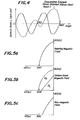
- Fig. 4 shows a magnetic torque curve of the plate-like permanent magnet produced by a series of the above production steps.
- the solid line shows a magnetic torque having a bidirectional orientation, which means that the permanent magnet has bidirectionally easy magnetization axes.
- dotted lines shows a magnetic torque curve of grain oriented silicon steel sheet produced by the usual production process.
- the easy magnetization axis may be formed in radial direction in plane. In this case, it is sufficient to control the growth direction of different phase in the two-phase separation.
- the two-phase separation annealing is carried out in a rotating magnetic field or while rotating the rolled plate in a magnetic field.
- the melt of Fe 59 Cr 24 Co 15 W 2 alloy composition was rapidly solidified by continuously feeding into a contact portion between the two rotating rolls to form a tape of 0.50 mm in thickness.
- a ring-like sample of 30 mm in outer diameter and 10 mm in inner diameter was punched out from the tape, and subjected to two-phase separation annealing at 660°C in a rotating magnetic field with an intensity of 10 kOe or in a unidirectional magnetic field with an intensity of 10 kOe or in the absence of magnetic field for 10 minutes, held at 610°C for 24 hours without applying the magnetic field, cooled down to 500°C at a rate of 10°C/hr, and then subjected to age annealing at 500°C for 24 hours.
- Figs. 5a-5c The magnetic properties of the thus obtained ring-like samples were measured to obtain results as shown in Figs. 5a-5c, wherein Fig. 5a is the case of annealing in the rotating magnetic field, Fig. 5b is the case of annealing in the unidirectional magnetic field and Fig. 5c is the case cf annealing in the non-magnetic field.
- H// is a case that the measurement is performed in a direction parallel to the direction of the magnetic field applied
- H L is a case that the measurement is performed in a direction perpendicular to the direction of the magnetic field applied.
- the melt of Fe 48 Cr 24 Co 15 W 4 alloy composition was poured into a mold to form an ingot, which was heated at 1280°C for 30 minutes and hot rolled to form a hot rolled sheet of 0.65 mm in thickness.
- This sheet was subjected to a solution treatment at 1280°C, from which a ring-like sample of 30 mm in outer diameter and 10 mm in inner diameter was punched out.
- the resulting sample was subjected to the same heat treatment as described above (i.e. two-phase separation annealing in the presence or absence of magnetic field and further age annealing), and thereafter the magnetic properties were measured to obtain results shown in Figs. 6a-6c, wherein R // is a case that the measurement is performed in a direction parallel to the rolling direction and R 1 is a case that the measurement is performed in a direction perpendicular to the rolling direction.
- the base plate of the fundamental alloy composition is shaped into a ring or disc by punching, etching or wire cutting before the heat treatment, if necessary. Thereafter, the base plate or its ring or disc is subjected to two-phase separation annealing in magnetic field as the heat treatment while rotating the magnetic field applied to the plate in a plane parallel thereto or rotating the plate under the application of unidirectional magnetic field.
- the direction of major axis in ⁇ 1 phase is influenced by the direction of magnetic field to form a so-called radial anisotropy wherein the major axis radially extends in the plane.
- the age annealing is performed as the heat treatment for more improving the magnetic properties obtained by the two-phase separation annealing.
- the base plate or its ring or disc is subjected to a solution treatment prior to the two-phase separation annealing.
- This solution treatment is to render the structure of the base plate into single a phase.
- the treating temperature is lower than 900°C, a long time is taken for the solution treatment, while when it exceeds 1300°C, the surface of the base plate may be fused. Therefore, the solution treatment is necessary to be carried out at a temperature of 900-1300°C.
- the base plate it is particularly preferable to use the tape obtained by rapidly solidifying the melt of the fundamental alloy composition as apparent from the following:
- Molten steel comprising 23% of Cr, 12% of Co, 0.1% of Ti, 0.1% of Si and the balance of Fe was shaped into a tape of 0.05 mm, 0.1 mm, 0.15 mm, 0.2 mm, 0.3 mm or 0.5 mm in thickness by a twin roll process.
- Each of the resulting tapes other than the tape of 0.05 mm in thickness was subjected to a first rolling at various draft, annealed in a non-oxidizing atmosphere at 850°C for 5 minutes and then rolled to a thickness of 0.05 mm. Separately, each of the above tapes was rolled to a thickness of 0.05 mm at once.
- the as-cast tape of 0.05 mm in thickness was not subjected to a rolling.
- the combination of first and second drafts is that the first draft is not less than 10% and the second draft is within a range of 50-80%.
- the rolled tape is subjected to recrystallization annealing at a temperature of 800-1300°C as a heat treatment.
- the temperature is lower than 800°C, the growth of crystal grains of ⁇ 100 ⁇ 001> orientation is insufficient and it is difficult to obtain a highly aligned texture of (100 ⁇ 001> orientation, while when it exceeds 1300°C, the industrialization is difficult from a viewpoint of technique and cost.
- the thus treated tape is subjected to an annealing inclusive of two-phase separation annealing at a temperature of 500-750°C as a further heat treatment, whereby spinodal decomposition is caused to enhance the coercive force.
- a temperature of 500-750°C a temperature of 500-750°C
- spinodal decomposition is caused to enhance the coercive force.
- the temperature is lower than 500°C, the decomposition rate is slow and the ageability is considerably degraded, while when it exceeds 750°C, y and a phases are included in a phase to deteriorate the magnetic properties.
- the latter annealing may be carried out in a magnetic field.
- the intensity of magnetic field is not less than 1 kOe and the direction of magnetic field applied is ⁇ 100> orientation.
- the thus obtained tape has ⁇ 100 ⁇ 001> orientation, so that the improving effect of magnetic properties is obtained even when the magnetic field is applied to the tape in any direction selected from the longitudinal direction of the tape, direction perpendicular to the longitudinal direction and direction perpendicular to the plane of the tape.
- multi-stage age annealing may be carried out after the separation annealing in magnetic field.
- the melt of the fundamental alloy composition is shaped into a tape by a rapid solidification process.
- the rapid solidification process there may be used the conventionally well-known processes such as single roll process, twin roll process and the- like.
- columnar structure produced in the rapid solidification of the alloy melt is positively utilized for aligning the easy magnetization axis in the direction perpendicular to the plane of the tape, and in this case it is important to control the crystal texture so that the solidification structure of the rapidly solidified tape contains at least 30% of columnar grain.
- the cooling may be performed at a revolution number of cooling roll of not less than 10 3 rpm. Since the cooling rate is proportional to the revolution number of cooling roll, the cooling rate in this example is at least 10 3 °C/sec. Moreover, when the tape thickness is more than 0.5 mm at the columnar grain rate of at least 30%, it is sufficient to change the cooling rate into not less than 10 4 °C/sec.
- the columnar structure at as-cast state means a structure that ⁇ 100 ⁇ face is parallel to the plane of the tape and ⁇ 001> orientation is perpendicular to the plane.
- Fig. 10a is a microphotograph in section of a rapidly solidified tape of Fe 62 Cr 22 Co 15 Mn 1 alloy composition with a thickness of 0.3 mm at as-cast state and Fig. 10b is (200) pole figure thereof, wherein the rate of columnar grain is more than 90%.
- this tape is subjected to recrystallization annealing at 1100°C for 10 minutes, the crystal grains are coarsened to form a macrograin passing through the thickness of the tape as shown in Fig. lla.
- the aligned texture viewed from the pole figure is ⁇ 100 ⁇ 0uw>, so that ⁇ 001> orientation is necessarily aligned in the direction perpendicular to the plane of the tape.
- Such ⁇ 001> orientation is an easy magnetization axis likewise the case of BCC alloys represented by Fe.
- the rapidly solidified tape obtained by the same method as mentioned above has a columnar grain rate of less than 30% (or a rate of cubic system of more than 70%) as shown in Fig. 12a, even if the recrystallization annealing is carried out at 1100°C for 10 minutes, the crystal grain does not pass through the thickness of the tape as shown in Fig. 13a.
- the aligned texture at as-cast state is ⁇ 100 ⁇ 0vw>, but the texture after the recrystallization annealing is rendered into random direction as shown in Fig. 13b. That is, the latter texture is random to the plane of the tape but not perpendicular to the plane.
- Such a behavior of crystal grain growth is due to the fact that the rate of cubic system included in a central portion of the tape at as-cast state is large.
- the columnar grain rate is not less than 30% or the rate of cubic system is less than 70% in order to align the easy magnetization axis in the direction perpendicular to the plane of the tape.
- the thus obtained tape may be subjected to a skin pass rolling without troubles.
- the rapidly solidified tape having a columnar grain rate of not less than 30% may be subjected to a recrystallization annealing at a temperature of 800-1300°C to grow crystal grains.
- the tape is subjected to two-phase separation annealing in magnetic field at a temperature of 600-750 0 C and age annealing at a temperature below the separation annealing temperature as a heat treatment to thereby improve the magnetic properties.
- the two-phase separation annealing it is required to apply the magnetic field to the tape in a direction perpendicular to the plane of the tape and the intensity of magnetic field is desirable to be not less than about 0.5 k0e.
- spinodal decomposition is carried out in a continuous furnace or the like capable of applying the magnetic field in the direction perpendicular to the plane of the tape.
- a melt of Fe 60 Cr 25 Co 15 alloy composition was injected from an injection nozzle onto a contact portion between two rotating cooled rolls to form a tape of 0.5 mm in thickness. Then, the resulting tape was subjected to a cold rolling at a draft varying from 0% to 95% and further to recrystallization annealing at 1250°C for about 30 minutes.
- the tapes obtained by rolling at a draft of 30-95% among the above tapes were confirmed to have ⁇ 110 ⁇ 001> orientation and then subjected to two-phase separation annealing at 660°C for 20 minutes while applying a magnetic field of 2 k0e to the tape toward ⁇ 001> orientation. Thereafter, the tape was immediately cooled down to 600°C and subjected to age annealing from 600°C to 500°C at a cooling rate of 5°C/hr.
- a melt of Fe 60 Cr 23 Co 15 Si 2 alloy composition was injected from an injection nozzle onto a contact portion between two rotating cooled rolls to form a tape of 0.5 mm in thickness.
- the resulting tape was rolled at a draft of 65% and then subjected to recrystallization annealing at 1000°C for 40 minutes. Thereafter, the tape was subjected to two-phase separation annealing in a magnetic field of 2 k0e at 655°C for 30 minutes, immediately cooled down to 600°C and then subjected to age annealing from 600°C to 500°C at a cooling rate of 5°C/hr.
- the coercive force and maximum energy product of the thus obtained tape were measured to obtain results as shown in the following Table 3.
- a melt of Fe 58.887 Cr 25 Co 15 Al 1 C 0.035 Mn 0.06 Se 0.018 alloy composition was shaped into an ingot of 10 kg, which was hot rolled to form a sheet of 3.0 mm in thickness. This sheet was annealed at 900°C for 5 minutes, cold rolled at a draft of 70% to a thickness of 0.9 mm and then subjected to an intermediate annealing at 950°C for 5 minutes. The thus treated sheet was subjected to a cold rolling at a second draft of 60% to form a thin sheet of 0.36 mm in final thickness, which was subjected to decarburization annealing at 850°C for 5 minutes and further to recrystallization annealing at 900°C for 5 hours.
- the thus treated thin sheet was subjected to two-phase separation annealing at 660°C for 10 minutes while applying a magnetic field of 2 k0e in the rolling direction and further to multi-stage age annealing at 600°C for 5 hours, at 575°C for 5 hours, at 550°C for 5 hours and at 500°C for 10 hours.
- a melt of Fe 59.821 Cr 23 Co 15 W 2 C 0.033 Bi 0.066 Sb 0.08 alloy composition was shaped into an ingot of 10 kg, which was hot rolled to form a sheet of 2.7 mm in thickness. This sheet was annealed at 900°C for 5 minutes, cold rolled at a draft of about 88% to a thickness of 0.325 mm and then subjected to decarburization annealing at 850°C and further to recrystallization annealing at 1100°C for 2 hours.
- the thus treated thin sheet was subjected to two-phase separation annealing at 660°C for 10 minutes while applying a magnetic field of 2 k0e in the rolling direction and further to multi-stage age annealing at 600°C for 5 hours, at 575°C for 5 hours and at 550°C for 10 hours.
- the thus obtained thin sheet had a maximum energy product (BH)max of 8.9 MGOe.
- a rapidly solidified tape of 0.70 mm in thickness was produced from a melt of Fe 62.808 Cr 22 Co 14 Ti 1 C 0.030 Mn 0.06 S 0.022 Sb 0.080 alloy composition by a twin roll process.
- This tape was annealed at 900°C for 5 minutes, rolled at a draft of 60% to a thickness of 0.28 mm, subjected to decarburization annealing in a hydrogen atmosphere at 850°C, recrystallization annealing at 800-900°C for 30 hours and normalizing annealing at 1200°C for 3 hours, and then cooled with water.
- the thus treated tape was subjected to two-phase separation annealing at 670°C for 15 minutes while applying a magnetic field of 2 kOe in the rolling direction and further to multi-stage age annealing at 600°C for 5 hours, at 575°C for 5 hours, at 550°C for 5 hours and at 500°C for 10 hours without the application of magnetic field.
- the thus obtained tape had a maximum energy product (BH)max of 8.5 MGOe.
- a melt having an alloy composition as shown in the following Table 5 was injected from an injection nozzle onto a contact portion between two rotating rolls to form a rapidly solidified tape of about 0.5 mm in thickness and about 10 cm in width. This tape was immediately cold rolled at a draft of 60% to a thickness of about 0.2 mm, annealed at 1200°C for 1 hour and rapidly cooled.
- An ingot was produced from a metl of Fe 61 Cr 25 Co 11 Al 2 Si 1 alloy composition in the usual manner, which was hot rolled to a thickness of 2 mm.
- the resulting hot rolled sheet was annealed at 900°C for 5 minutes, cold rolled at a draft shown in the following Table 6, subjected to recrystallization annealing at a temperature shown in Table 6 for about 1 hour, and then rapidly cooled.
- a melt having an alloy composition shown in the following Table 8 was injected from an injection nozzle onto a contact portion between two rotating cooled rolls to form a rapidly solidified tape of about 0.5 mm in thickness and about 10 cm in width. Then, the resulting tape was immediately cold rolled to a thickness of about 0.1 mm, subjected to decarburization annealing at 1000°C, quenched and then subjected to normalizing annealing at 1200°C for 2 hours, whereby the content of each of C, S, Se and Te was reduced to not more than 0.003%.
- the crystal texture of ⁇ 110 ⁇ 001> is highly aligned by the combination of rolling and heat treatment to effectively produce unidirectional magnetic anisotropy having a higher value of (BH)max.
- An ingot was produced from a melt of Fe 60 Cr 25 Co 15 alloy composition, which was hot rolled to a thickness of 3.0 mm in the usual manner. Then, the resulting hot rolled sheet was annealed at 1300°C for 30 minutes, cooled with water and then cold rolled at a draft of 90% to form a cold rolled sheet of 0.30 mm in thickness. A disc of 20 mm in diameter was punched out from the cold rolled sheet, which was subjected to two-phase separation annealing at 660°C for 60 minutes and further to age annealing at 600°C for 5 hours.
- the thus obtained sheet had a higher value of coercive force Hc of 620 Oe in a direction of two easy magnetization directions and a magnetic torque curve shown in Fig. 4.
- a melt of Fe 60 Cr 20 Co 13 B 0.5 Si 6.5 alloy composition was injected from an injection nozzle onto a contact portion between two rotating rolls to form a rapidly solidified tape of 0.50 mm in thickness.
- This tape was cold rolled at a draft of 82% to a thickness of 0.09 mm, from which was punched out a disc of 20 mm in diameter.
- the resulting disc was subjected to two-phase separation annealing at 670°C for 60 minutes and further to multi-stage age annealing at 620°C for 1 hour and at 600°C for 2 hours.
- the thus obtained disc-like tape had a higher value of coercive force Hc of 590 Oe in a direction of two easy magnetization directions and had the same magnetic torque curve as shown in Fig. 4.
- An ingot of 10 kg was produced from-a melt of Fe 57 Cr 23 Co 15 Al 3 Ti 2 alloy composition, which was hot-rolled to a thickness of 3.0 mm.
- the resulting hot rolled sheet was cold rolled in a direction perpendicular to the longitudinal direction of the sheet to form a cold rolled sheet of 0.30 mm in thickness.
- a disc of 20 mm in diameter was immediately punched out from the cold rolled sheet without solution treatment, and subjected to two-phase separation annealing in a rotating magnetic field of 10 kOe at 660°C for 30 minutes and further to multi-stage age annealing at 580°C for 1 hour, at 560°C for 1 hour, at 540°C for 1 hour, at 520°C for 1 hour and at 500°C for 5 hours.
- a melt of Fe 61 Cr 23 Co 14 Mo 2 alloy composition was injected from an injection nozzle onto a contact portion between two rotating rolls at a cooling rate of 10 4 °C/sec to form a rapidly solidified tape of 0.50 mm in thickness.
- a ring of 30 mm in outer diameter and 10 mm in inner diameter was punched out from the tape, subjected to two-phase separation annealing in a rotating magnetic field of 10 kOe or a unidirectional magnetic field of 10 k0e or in the absence of magnetic field at 650°C for 60 minutes, held at 600°C for 24 hours without the application of magnetic field, cooled down to 500°C at a cooling rate of 10°C/hr and then subjected to age annealing at 500°C for 24 hours.
- a melt of Fe 57 Cr 24 CO 15 V 4 alloy composition was rapidly solidified by a twin roll process to form a tape of 0.40 mm in thickness.
- a disc of 30 mm in diameter was punched out from the tape, subjected to two-phase separation annealing in a rotating magnetic field of 10 k0e or a unidirectional magnetic field of 10 k0e or in the absence of magnetic field at 680°C for 20 minutes, held at 600°C for 24 hours without the application of magnetic field, cooled down to 500°C at a cooling rate of 10°C/hr and then subjected to age annealing at 500°C for 24 hours.
- a melt of Fe 57 Cr 24 Co 15 W 4 alloy composition was poured from a melting furnace into a mold.
- the resulting ingot was heated at 1300°C and then subjected to the usual hot rolling and cold rolling to form a thin sheet of 0.65 mm in thickness.
- the ring was subjected to the same two-phase separation annealing as described above in a unidirectional magnetic field or in the absence of magnetic field instead of the rotating magnetic field and then the coercive force of the thus treated ring was measured to obtain results as shown in Table 13.
- An ingot of 10 kg was produced from a melt of Fe 58 Cr 22 Co 15 V 5 alloy composition, which was heated at 1300°C for 30 minutes and then subjected to the usual hot rolling and cold rolling to form a thin sheet of 0.40 mm in thickness. After the thin sheet was subjected to a solution treatment at 1250°C, a disc of 30 mm in diameter was punched out therefrom, subjected to two-phase separation annealing in a rotating magnetic field of 10 k0e or a unidirectional magnetic field of 10 k0e or in the absence of magnetic field at 650°C for 20 minutes, held at 600°C for 24 hours without the application of magnetic field, cooled down to 500°C at a cooling rate of 10°C/sec and then subjected to age annealing at 500°C for 12 hours.
- a melt having an alloy composition as shown in the following Table 15 was injected from an injection nozzle onto a contact portion between two rotating cooled rolls to form a rapidly solidified tape of about 0.5 mm in thickness and about 10 cm in width.
- a set of about 10 discs piled one upon the other was subjected to two-phase separation annealing in a rotating magnetic field of about 3 kOe at 670°C for about 1 hour, cooled from 600°C to 500°C over about 50 hours and then cooled in air.
- the magnetic properties of the thus treated disc set were measured to obtain results as shown in Table 15.
- Table 15 For the comparison, the magnetic properties of the disc set subjected to the two-phase separation annealing in the absence of magnetic field are also shown in Table 15.
- An ingot having an alloy composition as shown in the following Table 16 was hot rolled in the usual manner at a final temperature of about 800°C to form a hot rolled sheet of 1 mm in thickness. Then, the resulting sheet was subjected to a solution treatment by annealing at 1250°C for 1 hour and quenching. The thus treated sheet was shaped into a disc and subjected to two-phase separation annealing in a rotating magnetic field of about 3 kOe at 675°C for about 50 minutes. Thereafter, the disc was cooled from 650°C to 500°C over about 50 hours and then cooled in air. The magnetic properties of the thus treated disc were measured to obtain results as shown in Table 16. For the comparison, the magnetic properties of the disc without the solution treatment are also shown in Table 16.
- a melt having an alloy composition as shown in the following Table 17 was rapidly solidified by a twin roll process to form a tape of 0.5 mm in thickness and 20 mm in width. Then, the resulting tape was subjected to two-stage rolling at first and second drafts shown in Table 17 through an intermediate annealing in N 2 atmosphere at 830°C for 6 minutes to obtain a rolled tape of 0.1 mm in thickness.
- the rolled tape was heated at 1180°C, subjected to two-phase separation annealing under a vacuum of 2 X 10- 3 Torr for 3 hours, cooled with water and then subjected to age annealing at 680°C for 90 minutes.
- a melt having an alloy composition as shown in the following Table 18 was rapidly solidified by a twin roll process to form a tape of 0.2 mm in thickness and 30 mm in width.
- the resulting tape was rolled to a thickness of 0.15 mm (draft: 25%), annealed in H 2 +N 2 atmosphere at 870°C for 3 minutes and further rolled to a thickness of 0.07 mm (draft: about 53%).
- the thus treated tape was annealed in a hydrogen atmosphere at 1250°C for 2 hours, cooled with water and subjected to two-phase separation annealing at 690°C for 60 minutes while applying a magnetic field of 2 k0e in a direction perpendicular to the longitudinal direction of the tape and further to age annealing at 530°C for 10 hours.
- a melt having an alloy composition as shown in the following Table 19 was rapidly solidified by a twin roll process to form a tape of 0.5 mm in thickness. Then, the resulting tape was subjected to two-stage rolling at first and second drafts shown in Table 19 through an intermediate annealing in N 2 atmosphere at 830°C for 6 minutes to obtain a rolled tape of 0.1 mm in thickness. This rolled tape was subjected to two-phase separation annealing at 690°C for 60 minutes while applying a magnetic field of 2 kOe in a direction perpendicular to the longitudinal direction of the tape and further to age annealing at 530°C for 10 hours.
- a melt of Fe 65 Cr 22 Co 12 Mn 1 alloy composition was rapidly solidified by a twin roll process under conditions that the injection pressure was 1.5 atm, the injection amount was 0.5 kg/sec and the revolution number was 1200 rpm or 700 rpm to obtain a tape A of 0.3 mm in thickness or a tape B of 0.5 mm in thickness.
- the rate of columnar grain at as-cast state was about 80% in the tape A or about 28% in the tape B.
- Each of these tapes A and B was subjected to recrystallization annealing at 1000°C for 10 minutes, two-phase separation annealing at 660°C for L0 minutes while applying a magnetic field of 2 kOe in a direction perpendicular to the plane of the tape, and multi-stage age annealing at 600°C for 5 hours, at 575°C for 5 hours, at 550°C for 5 hours and at 500°C for 10 hours.
- a melt of Fe 60 Cr 23 Co 15 Si 1 alloy composition was rapidly solidified by a twin roll process under conditions that the injection pressure was 1.6 atm, the injection amount was 0.6 kg/sec and the revolution number of the roll was 300 rpm, 600 rpm or 1200 rpm to obtain a tape C of 0.20 mm in thickness, a tape D of 0.35 mm in thickness or a tape E of 0.52 mm in thickness.
- Each of these tapes C, D and E was subjected to recrystallization annealing at 980°C for 12 minutes, two-phase separation annealing at 665°C for 10 minutes while applying a magnetic field of 2 k0e in a direction perpendicular to the plane of the tape, and multi-stage age annealing at 600°C for 5 hours, at 575°C for 5 hours, at 550°C for 5 hours and at 500°C for 10 hours.
- the tapes C and D were 600 G, while the tape E was only 370 G.
- a melt of Fe 65 Cr 20 Co 15 alloy composition was rapidly solidified by a twin roll process to form a tape of 0.5 mm in thickness.
- the resulting tape was subjected to two-phase separation annealing at 650°C for 30 minutes while applying a magnetic field of 10 k0e in the thickness direction of the tape without the solution treatment and further to age annealing at 560°C for 50 hours.
- the maximum energy product (BH)max of the thus treated tape was 3.5 MOe.
- the tape was toroidally wound twice to form a ring, which was easily magnetized so as to exhibit S pole in the inside of the ring and N pole in the outside thereof.
- a melt having an alloy composition as shown in the following Table 20 was injected from an injection nozzle onto a contact portion between two rotating cooled rolls to form a rapidly solidified tape of 0.5 mm in thickness and 10 cm in width. After a disc of 20 mm in diameter was punched out from the tape, a set of 100 discs piled one upon the other was subjected to two-phase separation annealing at 665°C for 30 minutes while applying a magnetic field of 10 kOe in the piled direction of the tape, cooled from 640°C to 500°C over 50 hours and then cooled in air. The magnetic properties of the thus treated tape set were measured to obtain results as shown in Table 20. For the comparison, the magnetic properties of the thin sheets, which were produced from the same melt through ingot making, hot rolling and cold rolling and subjected to the same heat treatment as mentioned above, are also shown in Table 20.
- a melt having an alloy composition as shown in the following Table 21 was rapidly solidified by a twin roll process to form a tape of 0.4 mm in thickness and 10 cm in width.
- the tape having a columnar grain rate of 0-100% was formed by varying the cooling conditions.
- a disc of 20 mm in diameter was punched out from the tape.
- a set of 100 discs piled one upon the other was subjected to a two-phase separation annealing at 665°C for 30 minutes while applying a magnetic field of 10 kOe in the piled direction of the tape, cooled from 640°C to 500°C over 50 hours and then cooled in air.
- the maximum energy product (BH)max of the thus treated disc set was measured to obtain a results as shown in Table 21.
- the easy magnetization axis can be aligned in a direction perpendicular to plane by positively utilizing the arrangement of crystal texture inherent to the rapid solidification process. Further, since the direction of magnetic field applied in the two-phase separation annealing is coincident with the direction perpendicular to the plane, plate-like permanent magnets having improved magnetic properties in the direction perpendicular to the plane can easily be produced in an industrial scale. Moreover, when the plate-like magnet material is wound into a toroidal ring having optional width, thickness and diameter, such a ring exhibits a radial anisotropy, so that the magnetization in radial direction of ring is easy.
Applications Claiming Priority (4)
| Application Number | Priority Date | Filing Date | Title |
|---|---|---|---|
| JP204300/85 | 1985-09-18 | ||
| JP20430085A JPS6267116A (ja) | 1985-09-18 | 1985-09-18 | 一方向性永久磁石薄板の製造方法 |
| JP22380385A JPS6283423A (ja) | 1985-10-09 | 1985-10-09 | 板面垂直方向に磁化容易軸を有する永久磁石板の製造方法 |
| JP223803/85 | 1985-10-09 |
Publications (1)
| Publication Number | Publication Date |
|---|---|
| EP0216457A1 true EP0216457A1 (de) | 1987-04-01 |
Family
ID=26514402
Family Applications (1)
| Application Number | Title | Priority Date | Filing Date |
|---|---|---|---|
| EP19860305484 Withdrawn EP0216457A1 (de) | 1985-09-18 | 1986-07-16 | Verfahren zur Herstellung von Permanentmagneten der Zweiphasen-Trennungsserie des Fe-Cr-Co-Typs |
Country Status (1)
| Country | Link |
|---|---|
| EP (1) | EP0216457A1 (de) |
Cited By (10)
| Publication number | Priority date | Publication date | Assignee | Title |
|---|---|---|---|---|
| EP0447793A2 (de) * | 1990-03-21 | 1991-09-25 | Vacuumschmelze GmbH | Deaktivierbares Sicherungsetikett |
| WO2007088513A1 (en) * | 2006-01-31 | 2007-08-09 | Vacuumschmelze Gmbh & Co. Kg | Corrosion resistant magnetic component for a fuel injection valve |
| US7909945B2 (en) | 2006-10-30 | 2011-03-22 | Vacuumschmelze Gmbh & Co. Kg | Soft magnetic iron-cobalt-based alloy and method for its production |
| US7964043B2 (en) | 2001-07-13 | 2011-06-21 | Vacuumschmelze Gmbh & Co. Kg | Method for producing nanocrystalline magnet cores, and device for carrying out said method |
| US8012270B2 (en) | 2007-07-27 | 2011-09-06 | Vacuumschmelze Gmbh & Co. Kg | Soft magnetic iron/cobalt/chromium-based alloy and process for manufacturing it |
| US8029627B2 (en) | 2006-01-31 | 2011-10-04 | Vacuumschmelze Gmbh & Co. Kg | Corrosion resistant magnetic component for a fuel injection valve |
| US8287664B2 (en) | 2006-07-12 | 2012-10-16 | Vacuumschmelze Gmbh & Co. Kg | Method for the production of magnet cores, magnet core and inductive component with a magnet core |
| US8887376B2 (en) | 2005-07-20 | 2014-11-18 | Vacuumschmelze Gmbh & Co. Kg | Method for production of a soft-magnetic core having CoFe or CoFeV laminations and generator or motor comprising such a core |
| US9057115B2 (en) | 2007-07-27 | 2015-06-16 | Vacuumschmelze Gmbh & Co. Kg | Soft magnetic iron-cobalt-based alloy and process for manufacturing it |
| CN114277322A (zh) * | 2021-12-07 | 2022-04-05 | 王军 | 一种铁钴铬钨磁滞合金及其变形加工工艺 |
Citations (5)
| Publication number | Priority date | Publication date | Assignee | Title |
|---|---|---|---|---|
| US4194932A (en) * | 1977-02-10 | 1980-03-25 | Hitachi Metals | Fe/Cr/Co Permanent magnetic alloys and method of production thereof |
| US4284440A (en) * | 1976-06-18 | 1981-08-18 | Hitachi Metals, Ltd. | Rare earth metal-cobalt permanent magnet alloy |
| US4305764A (en) * | 1978-12-14 | 1981-12-15 | Hitachi Metals, Ltd. | Method of producing Fe/Cr/Co permanent magnet alloy |
| US4324597A (en) * | 1977-12-27 | 1982-04-13 | Mitsubishi Seiko Kabushiki Kaisha | Magnetic alloy |
| US4366007A (en) * | 1976-02-14 | 1982-12-28 | Inoue-Japax Research Incorporated | Permanent magnet and process for making same |
-
1986
- 1986-07-16 EP EP19860305484 patent/EP0216457A1/de not_active Withdrawn
Patent Citations (5)
| Publication number | Priority date | Publication date | Assignee | Title |
|---|---|---|---|---|
| US4366007A (en) * | 1976-02-14 | 1982-12-28 | Inoue-Japax Research Incorporated | Permanent magnet and process for making same |
| US4284440A (en) * | 1976-06-18 | 1981-08-18 | Hitachi Metals, Ltd. | Rare earth metal-cobalt permanent magnet alloy |
| US4194932A (en) * | 1977-02-10 | 1980-03-25 | Hitachi Metals | Fe/Cr/Co Permanent magnetic alloys and method of production thereof |
| US4324597A (en) * | 1977-12-27 | 1982-04-13 | Mitsubishi Seiko Kabushiki Kaisha | Magnetic alloy |
| US4305764A (en) * | 1978-12-14 | 1981-12-15 | Hitachi Metals, Ltd. | Method of producing Fe/Cr/Co permanent magnet alloy |
Cited By (13)
| Publication number | Priority date | Publication date | Assignee | Title |
|---|---|---|---|---|
| EP0447793A3 (en) * | 1990-03-21 | 1991-12-18 | Vacuumschmelze Gmbh | Security label capable of deactivation |
| EP0447793A2 (de) * | 1990-03-21 | 1991-09-25 | Vacuumschmelze GmbH | Deaktivierbares Sicherungsetikett |
| US7964043B2 (en) | 2001-07-13 | 2011-06-21 | Vacuumschmelze Gmbh & Co. Kg | Method for producing nanocrystalline magnet cores, and device for carrying out said method |
| US8887376B2 (en) | 2005-07-20 | 2014-11-18 | Vacuumschmelze Gmbh & Co. Kg | Method for production of a soft-magnetic core having CoFe or CoFeV laminations and generator or motor comprising such a core |
| GB2447223A (en) * | 2006-01-31 | 2008-09-10 | Vacuumschmelze Gmbh & Co Kg | Corrosion resistant magnetic component for a fuel injection valve |
| GB2447223B (en) * | 2006-01-31 | 2011-04-06 | Vacuumschmelze Gmbh & Co Kg | Corrosion resistant magnetic component for a fuel injection valve |
| US8029627B2 (en) | 2006-01-31 | 2011-10-04 | Vacuumschmelze Gmbh & Co. Kg | Corrosion resistant magnetic component for a fuel injection valve |
| WO2007088513A1 (en) * | 2006-01-31 | 2007-08-09 | Vacuumschmelze Gmbh & Co. Kg | Corrosion resistant magnetic component for a fuel injection valve |
| US8287664B2 (en) | 2006-07-12 | 2012-10-16 | Vacuumschmelze Gmbh & Co. Kg | Method for the production of magnet cores, magnet core and inductive component with a magnet core |
| US7909945B2 (en) | 2006-10-30 | 2011-03-22 | Vacuumschmelze Gmbh & Co. Kg | Soft magnetic iron-cobalt-based alloy and method for its production |
| US8012270B2 (en) | 2007-07-27 | 2011-09-06 | Vacuumschmelze Gmbh & Co. Kg | Soft magnetic iron/cobalt/chromium-based alloy and process for manufacturing it |
| US9057115B2 (en) | 2007-07-27 | 2015-06-16 | Vacuumschmelze Gmbh & Co. Kg | Soft magnetic iron-cobalt-based alloy and process for manufacturing it |
| CN114277322A (zh) * | 2021-12-07 | 2022-04-05 | 王军 | 一种铁钴铬钨磁滞合金及其变形加工工艺 |
Similar Documents
| Publication | Publication Date | Title |
|---|---|---|
| EP1197569B1 (de) | Fe-Ni Permalloy und Verfahren zu deren Herstellung | |
| JPS5929644B2 (ja) | 高透磁率アモルフアス合金の磁気特性改質方法 | |
| EP2513917B1 (de) | Seltenerdmagnet und dessen herstellungsverfahren | |
| EP0216457A1 (de) | Verfahren zur Herstellung von Permanentmagneten der Zweiphasen-Trennungsserie des Fe-Cr-Co-Typs | |
| EP1018751B1 (de) | Dünnes plattenmagnet mit mikrokristalline struktur | |
| EP0323125B1 (de) | Permanent-Magnet aus seltenen Erden | |
| JP2535963B2 (ja) | 磁気特性の優れた珪素鋼板およびその製造方法 | |
| Nachman et al. | 16 Percent Aluminum‐Iron Alloy Cold Rolled in the Order‐Disorder Temperature Range | |
| Tsuya et al. | Ribbon-form silicon-iron alloy containing around 6% silicon | |
| Arai et al. | Grain growth characteristics and magnetic properties of rapidly quenched silicon steel ribbons | |
| JP3594084B2 (ja) | 希土類合金薄帯の製造方法、希土類合金薄帯および希土類磁石 | |
| JPH0674460B2 (ja) | 電磁鋼板の製造法 | |
| EP0288637B1 (de) | Dauermagnet und sein Herstellungsverfahren | |
| Sugimoto et al. | The development of< 100> texture in Fe-Cr-Co-Mo permanent magnet alloys | |
| JP3667783B2 (ja) | 異方性ボンド磁石用原料粉末の製造方法 | |
| JPH06231917A (ja) | 希土類−遷移金属系永久磁石およびその製造方法 | |
| US4290827A (en) | Process for producing Ni-Fe magnetic tape cores | |
| JP4043613B2 (ja) | 過冷却液体領域を有するFe基硬磁性合金 | |
| KR100710613B1 (ko) | 주철을 이용한 Fe계 나노 결정 합금 및 그 제조 방법 | |
| JPH0845718A (ja) | 磁性材料と製造法 | |
| JP3568577B2 (ja) | 磁石の製造方法 | |
| JPS61288047A (ja) | 永久磁石合金の製造方法 | |
| JPH05315120A (ja) | 希土類焼結磁石およびその製造方法 | |
| Mukai et al. | Magnetic properties and microstructures of Fe‐Cr‐Co‐base cold‐rolled magnets | |
| JPH04214806A (ja) | 希土類異方性永久磁石粉末の製造法 |
Legal Events
| Date | Code | Title | Description |
|---|---|---|---|
| PUAI | Public reference made under article 153(3) epc to a published international application that has entered the european phase |
Free format text: ORIGINAL CODE: 0009012 |
|
| AK | Designated contracting states |
Kind code of ref document: A1 Designated state(s): DE FR GB NL SE |
|
| 17P | Request for examination filed |
Effective date: 19870427 |
|
| 17Q | First examination report despatched |
Effective date: 19880822 |
|
| STAA | Information on the status of an ep patent application or granted ep patent |
Free format text: STATUS: THE APPLICATION IS DEEMED TO BE WITHDRAWN |
|
| 18D | Application deemed to be withdrawn |
Effective date: 19890103 |
|
| RIN1 | Information on inventor provided before grant (corrected) |
Inventor name: SHISHIDO, HIROSHITECHNICAL RESEARCH DIV. Inventor name: GOTOH, SATOSHITECHNICAL RESEARCH DIV. Inventor name: ITO, YOTECHNICAL RESEARCH DIV. |