EP0216441A2 - Gerätesatz - Google Patents
Gerätesatz Download PDFInfo
- Publication number
- EP0216441A2 EP0216441A2 EP86303804A EP86303804A EP0216441A2 EP 0216441 A2 EP0216441 A2 EP 0216441A2 EP 86303804 A EP86303804 A EP 86303804A EP 86303804 A EP86303804 A EP 86303804A EP 0216441 A2 EP0216441 A2 EP 0216441A2
- Authority
- EP
- European Patent Office
- Prior art keywords
- tool
- tool set
- link
- links
- working tip
- Prior art date
- Legal status (The legal status is an assumption and is not a legal conclusion. Google has not performed a legal analysis and makes no representation as to the accuracy of the status listed.)
- Granted
Links
- 230000000875 corresponding effect Effects 0.000 description 3
- PXHVJJICTQNCMI-UHFFFAOYSA-N Nickel Chemical compound [Ni] PXHVJJICTQNCMI-UHFFFAOYSA-N 0.000 description 2
- 230000006835 compression Effects 0.000 description 2
- 238000007906 compression Methods 0.000 description 2
- 239000000463 material Substances 0.000 description 2
- 238000000034 method Methods 0.000 description 2
- 229920003023 plastic Polymers 0.000 description 2
- 239000004033 plastic Substances 0.000 description 2
- VYZAMTAEIAYCRO-UHFFFAOYSA-N Chromium Chemical compound [Cr] VYZAMTAEIAYCRO-UHFFFAOYSA-N 0.000 description 1
- 229910000639 Spring steel Inorganic materials 0.000 description 1
- 229910000831 Steel Inorganic materials 0.000 description 1
- RTAQQCXQSZGOHL-UHFFFAOYSA-N Titanium Chemical compound [Ti] RTAQQCXQSZGOHL-UHFFFAOYSA-N 0.000 description 1
- HCHKCACWOHOZIP-UHFFFAOYSA-N Zinc Chemical compound [Zn] HCHKCACWOHOZIP-UHFFFAOYSA-N 0.000 description 1
- 238000005452 bending Methods 0.000 description 1
- 238000005266 casting Methods 0.000 description 1
- 238000009750 centrifugal casting Methods 0.000 description 1
- 229940000425 combination drug Drugs 0.000 description 1
- 238000005242 forging Methods 0.000 description 1
- 238000003780 insertion Methods 0.000 description 1
- 230000037431 insertion Effects 0.000 description 1
- 238000005495 investment casting Methods 0.000 description 1
- 238000003754 machining Methods 0.000 description 1
- 229910052759 nickel Inorganic materials 0.000 description 1
- 239000002861 polymer material Substances 0.000 description 1
- 239000010959 steel Substances 0.000 description 1
- 239000010936 titanium Substances 0.000 description 1
- 229910052719 titanium Inorganic materials 0.000 description 1
- 239000011701 zinc Substances 0.000 description 1
- 229910052725 zinc Inorganic materials 0.000 description 1
Images
Classifications
-
- B—PERFORMING OPERATIONS; TRANSPORTING
- B25—HAND TOOLS; PORTABLE POWER-DRIVEN TOOLS; MANIPULATORS
- B25B—TOOLS OR BENCH DEVICES NOT OTHERWISE PROVIDED FOR, FOR FASTENING, CONNECTING, DISENGAGING OR HOLDING
- B25B13/00—Spanners; Wrenches
- B25B13/48—Spanners; Wrenches for special purposes
- B25B13/50—Spanners; Wrenches for special purposes for operating on work of special profile, e.g. pipes
- B25B13/52—Chain or strap wrenches
-
- B—PERFORMING OPERATIONS; TRANSPORTING
- B25—HAND TOOLS; PORTABLE POWER-DRIVEN TOOLS; MANIPULATORS
- B25G—HANDLES FOR HAND IMPLEMENTS
- B25G1/00—Handle constructions
- B25G1/08—Handle constructions with provision for storing tool elements
- B25G1/085—Handle constructions with provision for storing tool elements for screwdrivers, wrenches or spanners
-
- B—PERFORMING OPERATIONS; TRANSPORTING
- B25—HAND TOOLS; PORTABLE POWER-DRIVEN TOOLS; MANIPULATORS
- B25B—TOOLS OR BENCH DEVICES NOT OTHERWISE PROVIDED FOR, FOR FASTENING, CONNECTING, DISENGAGING OR HOLDING
- B25B13/00—Spanners; Wrenches
- B25B13/56—Spanner sets
-
- B—PERFORMING OPERATIONS; TRANSPORTING
- B25—HAND TOOLS; PORTABLE POWER-DRIVEN TOOLS; MANIPULATORS
- B25B—TOOLS OR BENCH DEVICES NOT OTHERWISE PROVIDED FOR, FOR FASTENING, CONNECTING, DISENGAGING OR HOLDING
- B25B23/00—Details of, or accessories for, spanners, wrenches, screwdrivers
- B25B23/16—Handles
-
- B—PERFORMING OPERATIONS; TRANSPORTING
- B25—HAND TOOLS; PORTABLE POWER-DRIVEN TOOLS; MANIPULATORS
- B25F—COMBINATION OR MULTI-PURPOSE TOOLS NOT OTHERWISE PROVIDED FOR; DETAILS OR COMPONENTS OF PORTABLE POWER-DRIVEN TOOLS NOT PARTICULARLY RELATED TO THE OPERATIONS PERFORMED AND NOT OTHERWISE PROVIDED FOR
- B25F1/00—Combination or multi-purpose hand tools
- B25F1/02—Combination or multi-purpose hand tools with interchangeable or adjustable tool elements
- B25F1/04—Combination or multi-purpose hand tools with interchangeable or adjustable tool elements wherein the elements are brought into working positions by a pivoting or sliding movement
Definitions
- tool sets which provide multiple sizes of open-end wrenches, or tool sets which provide various size sockets together with a socket drive and ratchet, or which provide multiple types and sizes of screwdrivers, or various size allen wrenches or the like are common in the art.
- tool sets which provide multiple sizes of open-end wrenches, or tool sets which provide various size sockets together with a socket drive and ratchet, or which provide multiple types and sizes of screwdrivers, or various size allen wrenches or the like are common in the art.
- wrenches, screwdrivers or other such hand tools available.
- this requires carrying a large number of tools, which is both inconvenient and sometimes impractical.
- it is difficult to keep track of the various tools provided with a set with the result that sometimes parts to the set become lost.
- nothing can be more frustrating than not being able to find a particular size tool when it is needed for a job.
- the invention seeks to provide a versatile tool set which provides in a single hand piece a plurality of tools which can be changed in rapid succession from one tool to the other.
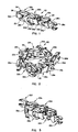
- one presently preferred embodiment of the chained tool set of the present invention is generally designated at 20.
- the chained tool set 20 may be linked together to form an endless loop.
- the chained tool set 20 may be disconnected between a pair of adjacent links so as to form simply a straight chain, a portion of which is illustrated in Figure 1. Either configuration is within the scope of the present invention.
- the chained tool set 20 comprises a plurality of tool links generally designated at 22a-22f.
- Each of the tool links 22 may be similarly formed so as to provide the same type of tool with each tool having a different size, such as the open-end wrench set illustrated in Figures 1 and 2, or as hereinafter more fully described, each tool link 22 may be formed so as to provide a different type of tool such as illustrated in Figures 9 and 10 discussed below.
- the tool links 22 can be manufactured using any suitable method, such as casting, machining, drop forging, investment casting or centrifugal casting.
- the tools can be constructed of any material suitable for a particular job or application such as steel with a finish of chrome, zinc, nickel or the like. Plastics may be used in forming the tool links when they are to be used in applications such as assembling childrens' plastic toys or the like. In cases where factors such as strength and weight govern over cost considerations, materials such as titanium or high strength polymer materials may be used.
- each tool link 22 is pivotally connected to an adjacent tool link by means of connecting links 32 and pins 34.
- the pins 34 are inserted through holes 35 which are provided at the ends of side members 24 and 25 of each tool link 22.
- the connecting links 32 are designed to be inserted in the space provided between side members 24 and 25, and connecting links 32 are also provided with corresponding holes 36 which receive the connecting pins 34.
- Pins 34 are constructed with a diameter which is large enough to provide a snug friction fit when inserted in the holes 35 and 36 of tool links 22 and connecting links 32. As hereinafter more fully described, pins 34 may be removed when it is desired to add additional tools into the chain and/or when it is desired to remove and replace worn tools.
- the working tip 28 of each tool extends from the end of one tool link and overlaps the end of an adjacent tool link. This helps to ensure that when the tool links 22 are connected together the pivoting action will be restrained so that the tool links will only be able to pivot in one direction. This helps to provide rigidity when using the chained tool set, particularly if the chained tool set is used in a configuration such as that illustrated in Figure 1 where the chain is straight rather than forming a loop as in the case of Figure 2.
- each tool link can be pivoted so as to open the chain as illustrated in Figure 2.
- the chain can then be folded or collapsed as shown in Figure 3 to form two parallel rows of tool links which serve as a rigid hand piece that is very strong and which can be firmly grasped when applying the torque or other force necessary to operate the tool.
- the tool 22f and 22c at either end of the collapsed chain may be in a working position similar to a conventional open-end wrench.
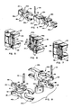
- Figures 5, 6 and 7 each illustrate alternative ways in which adjacent tool links 22 can be connected.
- the pin 34a may be threaded at one end 29 and provided with a slot 27 at the other end thereof so that the pin 34a can be screwed into one of the side members 25.
- the pin 34a can then be unscrewed and removed so as to disconnect the tool links.
- each connecting pin 34b is provided with a notch 31 and each connecting link 32' is provided with a corresponding slot 33 so that a retainer clip 37 can be clipped onto the connecting link 32' to engage the notch 31 of each connecting pin 34b.
- Retaining clip 37 is formed on its sides so that the leading ends 23 are bent inwardly whereas the middle portion 21 of the sides are bowed out, thus providing a compression or spring-like action which holds the retaining clip 37 in place once the portions 21 engage the notches 31 of connecting pins 34b.
- the retaining clip 37 can then be removed when it is desired to remove the connecting pins 34b for purposes of adding or replacing tools in the chain.
- connecting pin 34c is designed so as to permanently connect adjacent tool links.
- Connecting pin 34c comprises enlarged head members 39 at opposite ends thereof which may be formed after insertion of the pin by any of several techniques which are common in the art.
- the chained tool set of the present invention may be provided with tool links which are either capable of being disconnected or which are permanently attached to one another.
- Figure 8 illustrates another embodiment of a tool link which can be used to increase the rigidity and strength of the hand piece that is formed when the chain is collapsed as shown in Figure 3.
- two tool links are generally designated at 40a and 40b.
- Each tool link 40 comprises a working tip 28, which in Figure 8 is shown as an open-end wrench as illustrated at 28a and 28b, respectively.
- each tool link 40 is formed as an integral piece.
- each tool link 40 is constructed so that the side members 24 and 25 are joined to each other by a support member 41 formed toward the middle and between side members 24 and 25.
- the support member 41 has a semicircular slot 44 formed in it.
- a circular disk 52 may be provided in the slot 44 of every other tool link 40.
- the circular disk 52 is secured within the slot 44 by means of a retaining pin 48 which is received through holes 46 formed in the top and bottom of the semicircular slot 44, as shown best in tool link 40b of Figure 8.
- Retaining pin 48 may comprise a compression type pin constructed of spring steel with a seam-like gap 50 formed along its length which allows the retaining pin 48 to be compressed and inserted into the holes 46 provided at the top and bottom of the semicircular slot 44 as well as the corresponding hole provided in the disk 52.
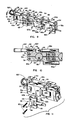
- the disk 52 functions as a key which engages the semicircular slot 44 of an adjacent tool link. Accordingly, as shown best in the cross-sectional view of Figure 10, when the chain is collapsed to form the hand piece which is gripped for purposes of operating a tool, the disk 52 engages the semicircular slot 44 of the adjacent tool link which then serves to hold the adjacent tool links so as to prevent them from slipping either longitudinally or laterally with respect to one another. As will be appreciated, this serves to provide additional strength and rigidity to the hand piece when using a selected tool. Moreover, the additional support member 41 which connects the side members 24 and 25 of each tool link 40 serves to provide additional strength and rigidity.
- each tool link 60a-60f of the chained tool set is similar to the tool links 40a and 40b described in Figure 8, except with respect to the manner in which the working tips 62a-62f are secured to the tool links.
- each tool link 60 is provided with a pair of arms 64 and 65 which extend outwardly and are formed as integral parts of the side members 24 and 25 of each link.
- the arms 64 and 65 are each provided with holes at their forward ends which receive a pivot pin 68 which is used to secure the tool between the arms 64 and 65.
- each tool comprises a suitable base 66 which has a bore through the base for receiving the pivot pin 68.
- each tool Extending from the base 66a of each tool is the working tip 62a for the particular type of tool desired.
- tool 62a is a conventional screwdriver tip
- tool 62b is a conventional socket drive
- tool 62c has a working tip formed as a conventional allen wrench
- tool 62e ( Figure 10) is a phillips screwdriver tip
- tool 62f has a working tip formed as a box-end wrench.
- the base 66 of the tool is designed to swivel about the pivot pin 68 which secures the tool base 66 between the arms 64 and 65 of the tool link 60.
- each tool may be positioned in one of several positions when using the tool to perform work.
- each tool is secured by means of the pivot pin 68, which is provided with a plurality of detents 70 about its periphery.
- the detents 70 are engaged by a ball 72 that is held by a spring 74.
- Spring 74 in turn is secured by a threaded plug 76 which may be screwed into a bore 78 provided along the length of the arms 64 and 65. Accordingly, each tool will click into position as it is swiveled about the pivot pin 68 to a point where the ball 72 will engage one of the detents 70 provided on the pivot pin 68.
- the embodiment of Figure 9 therefore has the added advantage that any tool provided on the chained tool set can be moved to a working position rather than having to move the particular tool to the end of the chain as in the case of the embodiments previously described.
- screwdriver 62a could also be swiveled about the pivot pin 68 to the same position shown by allen wrench 62c so that either tool could be used without having to move the screwdriver 62a to the end of the chain.
- each tool link 60 is essentially the same as the tool links described in Figures 9 and 10 except that in the embodiment of Figure 11 the arms 86 and 88 to which the working tips 62 are secured are mounted to the tool link by means of screws 90.
- the arms 86 and 88 between which the base 66 of the tool is pivotally secured by pin 68 are formed as part of a c-shaped member 82.
- Member 82 is provided with holes 84 through which the screws 90 engage threaded holes 92 provided on the side members 24 and 25 of the tool link.
- the present invention thus provides a versatile tool set com strictlyprised of tool links connected together to form a chain which provides in a single hand piece a plurality of tools which can be changed in rapid succession from one tool to the other.
- the chained tool set of the present invention is compact and versatile in that the various tools can be replaced and/or additional tools can be added to the chain, and is convenient since there are no loose parts in the tool set which can be lost or misplaced.
- any tool can be selected and used without the need for removing, reconnecting or replacing parts on the hand piece.
- Selected combinations of tools may be attached to the chain for purposes of providing specific tool sets for any given application which requires a combination of tools.
Landscapes
- Engineering & Computer Science (AREA)
- Mechanical Engineering (AREA)
- Automatic Tool Replacement In Machine Tools (AREA)
- Processing Of Terminals (AREA)
- Portable Power Tools In General (AREA)
- Radiation-Therapy Devices (AREA)
- Other Liquid Machine Or Engine Such As Wave Power Use (AREA)
- Transition And Organic Metals Composition Catalysts For Addition Polymerization (AREA)
- Hand Tools For Fitting Together And Separating, Or Other Hand Tools (AREA)
- Sampling And Sample Adjustment (AREA)
- Press Drives And Press Lines (AREA)
- Forklifts And Lifting Vehicles (AREA)
Priority Applications (1)
| Application Number | Priority Date | Filing Date | Title |
|---|---|---|---|
| AT86303804T ATE54862T1 (de) | 1985-09-16 | 1986-05-19 | Geraetesatz. |
Applications Claiming Priority (2)
| Application Number | Priority Date | Filing Date | Title |
|---|---|---|---|
| US06/776,426 US4606247A (en) | 1985-09-16 | 1985-09-16 | Versatile chained tool set |
| US776426 | 1985-09-16 |
Publications (3)
| Publication Number | Publication Date |
|---|---|
| EP0216441A2 true EP0216441A2 (de) | 1987-04-01 |
| EP0216441A3 EP0216441A3 (en) | 1988-01-27 |
| EP0216441B1 EP0216441B1 (de) | 1990-07-25 |
Family
ID=25107345
Family Applications (1)
| Application Number | Title | Priority Date | Filing Date |
|---|---|---|---|
| EP86303804A Expired - Lifetime EP0216441B1 (de) | 1985-09-16 | 1986-05-19 | Gerätesatz |
Country Status (10)
| Country | Link |
|---|---|
| US (1) | US4606247A (de) |
| EP (1) | EP0216441B1 (de) |
| JP (1) | JPS6263067A (de) |
| KR (1) | KR900006376B1 (de) |
| AT (1) | ATE54862T1 (de) |
| AU (1) | AU573090B2 (de) |
| CA (1) | CA1253661A (de) |
| DE (1) | DE3672932D1 (de) |
| HK (1) | HK40192A (de) |
| SG (1) | SG20492G (de) |
Cited By (4)
| Publication number | Priority date | Publication date | Assignee | Title |
|---|---|---|---|---|
| FR2697771A1 (fr) * | 1992-11-12 | 1994-05-13 | Robert Philippe | Manche pour outils à main totalement articulé sur un seul plan. |
| RU2274542C1 (ru) * | 2004-07-28 | 2006-04-20 | Алексей Борисович Хохряков | Инструмент для монтажа-демонтажа резьбовых соединений |
| CN108527223A (zh) * | 2017-04-21 | 2018-09-14 | 叶雨玲 | 多功能手动工具组 |
| CN109176376A (zh) * | 2018-09-07 | 2019-01-11 | 国网黑龙江省电力有限公司检修公司 | 手链式万用螺丝刀及工作方法 |
Families Citing this family (14)
| Publication number | Priority date | Publication date | Assignee | Title |
|---|---|---|---|---|
| USD306127S (en) | 1986-12-31 | 1990-02-20 | Chain-Tool Company, Inc. | Collapsible wrench set |
| JPS63267170A (ja) * | 1987-04-24 | 1988-11-04 | 矢崎 哲也 | 万能手持ち器具 |
| US5983759A (en) * | 1998-04-13 | 1999-11-16 | Turner; Paul E. | Folding wrench cluster |
| GB2378406B (en) * | 2001-08-07 | 2004-12-08 | Chih-Ching Hsieh | Multisection wrench |
| US7343837B1 (en) | 2006-09-15 | 2008-03-18 | James Anthony Domanico | Multi-plane flexible handle for ratchets and wrenches |
| GB2458544B (en) * | 2008-07-08 | 2011-06-08 | Malory Maltby | Variable radius lever arm assembly |
| CN104275665A (zh) * | 2013-07-12 | 2015-01-14 | 鑫爵实业股份有限公司 | 扳手结构 |
| US9578962B2 (en) | 2013-08-20 | 2017-02-28 | The Boeing Company | Translating stowage bin and method of assembly |
| US9187177B2 (en) * | 2013-08-20 | 2015-11-17 | The Boeing Company | Translating stowage bin and method of assembly |
| US9833048B2 (en) | 2014-01-07 | 2017-12-05 | Leatherman Tool Group, Inc. | Tool having interconnected links that form at least a portion of a wearable accessory |
| US20160229040A1 (en) * | 2015-02-06 | 2016-08-11 | Cheng-Pu Yang | Wrench |
| US20180368384A1 (en) * | 2017-06-21 | 2018-12-27 | Esther Kim | Extendable and Adjustable Insect Entrapment Apparatus |
| US20190000194A1 (en) * | 2017-06-28 | 2019-01-03 | Leatherman Tool Group, Inc. | Adjustable linkage and an associated wearable accessory having a plurality of interconnected links with tools |
| TWI904043B (zh) * | 2025-04-18 | 2025-11-01 | 耕澤實業有限公司 | 扳手結構 |
Family Cites Families (20)
| Publication number | Priority date | Publication date | Assignee | Title |
|---|---|---|---|---|
| US384592A (en) * | 1888-06-12 | Combination implement | ||
| GB1095444A (de) * | 1900-01-01 | |||
| US472147A (en) * | 1892-04-05 | Co m bi nation-tool | ||
| US992913A (en) * | 1910-03-10 | 1911-05-23 | William A Seils | Wrench. |
| GB191112825A (en) * | 1911-05-29 | 1912-04-11 | William Eggleton | An Improvement relating to Spanners for Screw Nuts. |
| US1169496A (en) * | 1915-01-27 | 1916-01-25 | Harry A Knauff | Folding street-wrench. |
| US1316398A (en) * | 1918-11-30 | 1919-09-16 | Peter Z Steininger | Wrench. |
| US1464132A (en) * | 1922-04-01 | 1923-08-07 | Fred L Haggardt | Socket wrench |
| GB270120A (en) * | 1926-11-26 | 1927-05-05 | Walter Pickard | Improvements in or relating to combination sets of spanners and the like |
| US2097361A (en) * | 1936-07-16 | 1937-10-26 | John J Bagley | Wrench |
| US2199899A (en) * | 1939-06-14 | 1940-05-07 | William F Watson | Compound tool |
| US2426763A (en) * | 1943-10-06 | 1947-09-02 | Earl M Curtis | Curved handle wrench for relatively inaccessible threaded objects |
| GB575169A (en) * | 1944-01-03 | 1946-02-06 | Robert Wood | Improvements in or relating to flat spanners |
| US2504345A (en) * | 1946-03-25 | 1950-04-18 | Chancey D Nellis | Wheel changing tool |
| US2951405A (en) * | 1957-12-09 | 1960-09-06 | Bahco Ab | Multiple grip wrench |
| FR1240971A (fr) * | 1959-11-18 | 1960-09-09 | Mousqueton porte-clés de serrage à douille à branches mobiles repliables et ouvrantes formant poignée d'entraînement | |
| US3039339A (en) * | 1960-04-08 | 1962-06-19 | Harris G Hanson | Handle with selectively usable wrench heads attaching units |
| US3188895A (en) * | 1964-01-21 | 1965-06-15 | Hobert B Jones | Flexible chain extension or shank for tools with lock link features |
| US4269311A (en) * | 1979-10-30 | 1981-05-26 | Rich Jackson E | Portable hand carried kit for a set of wrenches and the like |
| US4384499A (en) * | 1981-03-20 | 1983-05-24 | Harmon P. Yates | Tool set of the type having slide-out and swing-out tools |
-
1985
- 1985-09-16 US US06/776,426 patent/US4606247A/en not_active Expired - Lifetime
-
1986
- 1986-05-19 EP EP86303804A patent/EP0216441B1/de not_active Expired - Lifetime
- 1986-05-19 AT AT86303804T patent/ATE54862T1/de not_active IP Right Cessation
- 1986-05-19 DE DE8686303804T patent/DE3672932D1/de not_active Expired - Fee Related
- 1986-05-22 AU AU57810/86A patent/AU573090B2/en not_active Ceased
- 1986-06-04 JP JP61130013A patent/JPS6263067A/ja active Granted
- 1986-07-25 CA CA000514731A patent/CA1253661A/en not_active Expired
- 1986-08-11 KR KR1019860006581A patent/KR900006376B1/ko not_active Expired
-
1992
- 1992-02-29 SG SG204/92A patent/SG20492G/en unknown
- 1992-06-04 HK HK401/92A patent/HK40192A/en not_active IP Right Cessation
Cited By (5)
| Publication number | Priority date | Publication date | Assignee | Title |
|---|---|---|---|---|
| FR2697771A1 (fr) * | 1992-11-12 | 1994-05-13 | Robert Philippe | Manche pour outils à main totalement articulé sur un seul plan. |
| RU2274542C1 (ru) * | 2004-07-28 | 2006-04-20 | Алексей Борисович Хохряков | Инструмент для монтажа-демонтажа резьбовых соединений |
| CN108527223A (zh) * | 2017-04-21 | 2018-09-14 | 叶雨玲 | 多功能手动工具组 |
| CN108527223B (zh) * | 2017-04-21 | 2019-09-27 | 胡佳威 | 多功能手动工具组以及组装方法 |
| CN109176376A (zh) * | 2018-09-07 | 2019-01-11 | 国网黑龙江省电力有限公司检修公司 | 手链式万用螺丝刀及工作方法 |
Also Published As
| Publication number | Publication date |
|---|---|
| AU573090B2 (en) | 1988-05-26 |
| CA1253661A (en) | 1989-05-09 |
| HK40192A (en) | 1992-06-12 |
| JPH0553585B2 (de) | 1993-08-10 |
| DE3672932D1 (de) | 1990-08-30 |
| AU5781086A (en) | 1987-03-19 |
| JPS6263067A (ja) | 1987-03-19 |
| ATE54862T1 (de) | 1990-08-15 |
| EP0216441B1 (de) | 1990-07-25 |
| KR870002910A (ko) | 1987-04-13 |
| US4606247A (en) | 1986-08-19 |
| SG20492G (en) | 1992-04-16 |
| EP0216441A3 (en) | 1988-01-27 |
| KR900006376B1 (ko) | 1990-08-30 |
Similar Documents
| Publication | Publication Date | Title |
|---|---|---|
| EP0216441B1 (de) | Gerätesatz | |
| US6578222B2 (en) | Tool bit drive adaptor | |
| CN101743101B (zh) | 具有多个刀头存储器的手工工具及其使用方法 | |
| US5245721A (en) | Combination tool | |
| EP1210210B1 (de) | Handwerkzeug mit drehbarem arm | |
| US6626071B2 (en) | Multi-functional hand tool assembly with storage handle and multiple tool attachments | |
| AU702369B2 (en) | Self-forming socket | |
| USRE44675E1 (en) | Foldable tool with single beam construction | |
| US9533407B1 (en) | Pivotal double-ended multisockets | |
| US6598503B1 (en) | Tool handle | |
| GB2141067A (en) | Convertible pliers | |
| US20100107828A1 (en) | Adjustable Handle System for Fastening Tools That Drive Threaded Fasteners | |
| US5526723A (en) | Striking tool | |
| US20010049983A1 (en) | Multi-drive specialty tool | |
| US5910174A (en) | Pliers-based, combination tool | |
| US9770820B1 (en) | Folding pliers with full wrench set | |
| GB2610933A (en) | Multiple-bit hand tool including power nut/bit driver | |
| US20030213343A1 (en) | Rotary insert bits and hand tools | |
| US4987626A (en) | Locking pliers with screwdriver handles | |
| US11794317B2 (en) | Multipurpose tool | |
| US20040226418A1 (en) | Flexible drive wrench handle | |
| US20210101265A1 (en) | Driver Extension with Hand Knobs | |
| CN211029793U (zh) | 一种多功能便携式螺丝刀 |
Legal Events
| Date | Code | Title | Description |
|---|---|---|---|
| PUAI | Public reference made under article 153(3) epc to a published international application that has entered the european phase |
Free format text: ORIGINAL CODE: 0009012 |
|
| AK | Designated contracting states |
Kind code of ref document: A2 Designated state(s): AT BE CH DE FR GB IT LI LU NL SE |
|
| PUAL | Search report despatched |
Free format text: ORIGINAL CODE: 0009013 |
|
| AK | Designated contracting states |
Kind code of ref document: A3 Designated state(s): AT BE CH DE FR GB IT LI LU NL SE |
|
| 17P | Request for examination filed |
Effective date: 19880226 |
|
| 17Q | First examination report despatched |
Effective date: 19890609 |
|
| GRAA | (expected) grant |
Free format text: ORIGINAL CODE: 0009210 |
|
| AK | Designated contracting states |
Kind code of ref document: B1 Designated state(s): AT BE CH DE FR GB IT LI LU NL SE |
|
| REF | Corresponds to: |
Ref document number: 54862 Country of ref document: AT Date of ref document: 19900815 Kind code of ref document: T |
|
| REF | Corresponds to: |
Ref document number: 3672932 Country of ref document: DE Date of ref document: 19900830 |
|
| ET | Fr: translation filed | ||
| ITF | It: translation for a ep patent filed | ||
| PLBE | No opposition filed within time limit |
Free format text: ORIGINAL CODE: 0009261 |
|
| STAA | Information on the status of an ep patent application or granted ep patent |
Free format text: STATUS: NO OPPOSITION FILED WITHIN TIME LIMIT |
|
| 26N | No opposition filed | ||
| PGFP | Annual fee paid to national office [announced via postgrant information from national office to epo] |
Ref country code: CH Payment date: 19930414 Year of fee payment: 8 |
|
| PGFP | Annual fee paid to national office [announced via postgrant information from national office to epo] |
Ref country code: SE Payment date: 19930415 Year of fee payment: 8 |
|
| PGFP | Annual fee paid to national office [announced via postgrant information from national office to epo] |
Ref country code: AT Payment date: 19930419 Year of fee payment: 8 |
|
| PGFP | Annual fee paid to national office [announced via postgrant information from national office to epo] |
Ref country code: BE Payment date: 19930422 Year of fee payment: 8 |
|
| PGFP | Annual fee paid to national office [announced via postgrant information from national office to epo] |
Ref country code: LU Payment date: 19930428 Year of fee payment: 8 |
|
| ITTA | It: last paid annual fee | ||
| EPTA | Lu: last paid annual fee | ||
| PG25 | Lapsed in a contracting state [announced via postgrant information from national office to epo] |
Ref country code: LU Free format text: LAPSE BECAUSE OF NON-PAYMENT OF DUE FEES Effective date: 19940519 Ref country code: AT Effective date: 19940519 |
|
| PG25 | Lapsed in a contracting state [announced via postgrant information from national office to epo] |
Ref country code: SE Effective date: 19940520 |
|
| PG25 | Lapsed in a contracting state [announced via postgrant information from national office to epo] |
Ref country code: LI Effective date: 19940531 Ref country code: CH Effective date: 19940531 Ref country code: BE Effective date: 19940531 |
|
| BERE | Be: lapsed |
Owner name: HOGAN SCOTT HESS Effective date: 19940531 |
|
| EUG | Se: european patent has lapsed |
Ref document number: 86303804.8 Effective date: 19941210 |
|
| REG | Reference to a national code |
Ref country code: CH Ref legal event code: PL |
|
| EUG | Se: european patent has lapsed |
Ref document number: 86303804.8 |
|
| PGFP | Annual fee paid to national office [announced via postgrant information from national office to epo] |
Ref country code: GB Payment date: 19960520 Year of fee payment: 11 |
|
| PGFP | Annual fee paid to national office [announced via postgrant information from national office to epo] |
Ref country code: FR Payment date: 19960523 Year of fee payment: 11 |
|
| PGFP | Annual fee paid to national office [announced via postgrant information from national office to epo] |
Ref country code: DE Payment date: 19960524 Year of fee payment: 11 |
|
| PGFP | Annual fee paid to national office [announced via postgrant information from national office to epo] |
Ref country code: NL Payment date: 19960531 Year of fee payment: 11 |
|
| PG25 | Lapsed in a contracting state [announced via postgrant information from national office to epo] |
Ref country code: GB Effective date: 19970519 |
|
| PG25 | Lapsed in a contracting state [announced via postgrant information from national office to epo] |
Ref country code: NL Effective date: 19971201 |
|
| GBPC | Gb: european patent ceased through non-payment of renewal fee |
Effective date: 19970519 |
|
| PG25 | Lapsed in a contracting state [announced via postgrant information from national office to epo] |
Ref country code: FR Free format text: LAPSE BECAUSE OF NON-PAYMENT OF DUE FEES Effective date: 19980130 |
|
| NLV4 | Nl: lapsed or anulled due to non-payment of the annual fee |
Effective date: 19971201 |
|
| PG25 | Lapsed in a contracting state [announced via postgrant information from national office to epo] |
Ref country code: DE Free format text: LAPSE BECAUSE OF NON-PAYMENT OF DUE FEES Effective date: 19980203 |
|
| REG | Reference to a national code |
Ref country code: FR Ref legal event code: ST |
|
| PG25 | Lapsed in a contracting state [announced via postgrant information from national office to epo] |
Ref country code: IT Free format text: LAPSE BECAUSE OF NON-PAYMENT OF DUE FEES;WARNING: LAPSES OF ITALIAN PATENTS WITH EFFECTIVE DATE BEFORE 2007 MAY HAVE OCCURRED AT ANY TIME BEFORE 2007. THE CORRECT EFFECTIVE DATE MAY BE DIFFERENT FROM THE ONE RECORDED. Effective date: 20050519 |