EP0215745B1 - Maschine zum Waschen, Brechen und Walken von Geweben durch pneumatisches Einschleppen - Google Patents
Maschine zum Waschen, Brechen und Walken von Geweben durch pneumatisches Einschleppen Download PDFInfo
- Publication number
- EP0215745B1 EP0215745B1 EP86830235A EP86830235A EP0215745B1 EP 0215745 B1 EP0215745 B1 EP 0215745B1 EP 86830235 A EP86830235 A EP 86830235A EP 86830235 A EP86830235 A EP 86830235A EP 0215745 B1 EP0215745 B1 EP 0215745B1
- Authority
- EP
- European Patent Office
- Prior art keywords
- fabric
- machine
- per
- duct
- dragging
- Prior art date
- Legal status (The legal status is an assumption and is not a legal conclusion. Google has not performed a legal analysis and makes no representation as to the accuracy of the status listed.)
- Expired
Links
- 239000004744 fabric Substances 0.000 title claims description 56
- 238000009963 fulling Methods 0.000 title claims description 3
- 238000005406 washing Methods 0.000 title claims description 3
- 238000007493 shaping process Methods 0.000 claims description 11
- 238000011144 upstream manufacturing Methods 0.000 claims description 3
- 230000000694 effects Effects 0.000 description 4
- 239000007788 liquid Substances 0.000 description 3
- 239000003599 detergent Substances 0.000 description 1
- 238000007689 inspection Methods 0.000 description 1
- 230000002093 peripheral effect Effects 0.000 description 1
- XLYOFNOQVPJJNP-UHFFFAOYSA-N water Substances O XLYOFNOQVPJJNP-UHFFFAOYSA-N 0.000 description 1
Images

Classifications
-
- D—TEXTILES; PAPER
- D06—TREATMENT OF TEXTILES OR THE LIKE; LAUNDERING; FLEXIBLE MATERIALS NOT OTHERWISE PROVIDED FOR
- D06B—TREATING TEXTILE MATERIALS USING LIQUIDS, GASES OR VAPOURS
- D06B3/00—Passing of textile materials through liquids, gases or vapours to effect treatment, e.g. washing, dyeing, bleaching, sizing, impregnating
- D06B3/28—Passing of textile materials through liquids, gases or vapours to effect treatment, e.g. washing, dyeing, bleaching, sizing, impregnating of fabrics propelled by, or with the aid of, jets of the treating material
-
- D—TEXTILES; PAPER
- D06—TREATMENT OF TEXTILES OR THE LIKE; LAUNDERING; FLEXIBLE MATERIALS NOT OTHERWISE PROVIDED FOR
- D06C—FINISHING, DRESSING, TENTERING OR STRETCHING TEXTILE FABRICS
- D06C17/00—Fulling
-
- D—TEXTILES; PAPER
- D06—TREATMENT OF TEXTILES OR THE LIKE; LAUNDERING; FLEXIBLE MATERIALS NOT OTHERWISE PROVIDED FOR
- D06C—FINISHING, DRESSING, TENTERING OR STRETCHING TEXTILE FABRICS
- D06C19/00—Breaking or softening of fabrics
Definitions
- the invention relates to a machine that is of use for carrying out a treatment operation of the fabric, suitable to prepare said fabric for the finishing, and in particular to a machine that operates a washing, a bringing together of wefts and warp yarns of the fabric, and an at least partial fulling of the fabric ; this machine is of use for the treatment of light fabrics and also of heavy fabrics and in particular of relatively stiff fabrics.
- Similar machines usually provide a wall, against which the fabric is pushed or thrown more or less violently, which fabric there undergoes the mentioned treatment before going back to the lower tank shaped part with water and cleansing agents wherefrom the fabric is taken again to be once more thrown towards the wall.
- the inclination of this wall can be adjustable, in respect to the throwing direction of the fabric.
- the purpose of the machine, object of this invention is to carry out with greater efficiency the mentioned treatment and then obtain a better result on the fabric, even with shorter times of treatment.
- a machine comprises - in combination with a wall towards which the fabric is directed in order to strike against said wall and undergo the action thereof - a duct for the dragging of the fabric ; means to feed said fabric to said duct ; and means to convey a dragging air stream towards the outlet of said duct for the dragging of the fabric, in order to project it pneumatically against said wall, that is grid shaped and angularly adjustable.
- the direction of the projection of the fabric can be oriented towards the grid-shaped wall and upwards.
- Said means of conveyance can have a portion forming an annular nozzle around the outlet of the fabric duct ; a shaping of the dragging duct and a shaping of a pneumatic pipe surrounding said duct for the dragging of the fabric can cooperate to carry out the portion forming the nozzle ; these two shapings can be axially adjustable to each other.
- the means of feeding the fabric can include a couple of cylinders - per se known - through which the fabric is passed, and the speed of said cylinders is settled depending on the fabric requirement.
- a means to push the air - like a fan - sucks it from the inside and/or the outside of the working casing, and is connected to said pipe upstream in respect to the shapings.
- the machine can also comprise means for supporting the fabric, along the trajectory of the projection towards the grid.
- Said means can be pneumatic. They can include longitudinal ducts or canalizations at least in the lower area of the duct for the pneumatic projection, and/or a lower grid type structure to blow the air into the duct of pneumatic projection, and/or a second nozzle for the impulsion of the fabric.
- number 1 indicates a tank defined by the bottom of a chamber which can be closed at the upper side 1A and shows suitable means for the entrance, with inspection and checking doors.
- the upper closing wall 1A slants upwards and towards the end 1 B of the casing itself, and at this end 1 B a grid type wall 3 is placed, articulated at 5 and thus so predisposed that its slant can be angularly adjusted in respect to the vertical line.
- an air jet for the transportation is carried out, which is of use for dragging and projecting a fabric against the grid wall 3, being the fabric part of one piece (or several pieces) that is closed in such a way as to form a ring - simple or multiple - and is contained in the casing 1, 1A, being the fabric able to plunge into the liquid contained in the bottom of the tank 1, to be repeatedly recycled and projected against the grid wall 3.
- the fabric, indicated by T, is drawn upwards according to the arrowfT by an assembly of two dragging cylinders 7 and 8, one of them at least being driven into rotation at an adjustable speed and the other being urged towards the first one and possibly being driven into rotation at the same peripheral speed to drag the lifted fabric and feed it according to a trajectory T1 to a duct 9 for the pneumatic dragging of the fabric.
- This duct 9 shows an enlarged area 9A with a double truncated cone profile, which extends and ends with an outlet 9B adjacent to the truncated cone portion which is tapering towards said outlet.
- the axis of the duct 9, 9A, 9B is oriented towards the grid wall 3 and upwards.
- the duct 9, 9A, 9B is surrounded by a pipe 10 that is fed by compressed air through a duct 12 that is deviated in respect to the axis of the assembly 9,10, and comes from a fan 14 ; said fan sucks from an inlet 16 lying below the assembly 9, 10 inside the casing 1, 1A, or still inside the casing 1, 1 A - above the assembly 9, 10, or sucks from the outside or partially form the inside and partially from the outside.
- the pipe 12, 10 extends beyond the outlet 9B with a portion 10A extending towards the grid 3 and upwards as shown in the drawing.
- the stream of air pushed by the fan 14 forms a means of pneumatic conveyance for the fabric that comes out from the outlet 9B of the duct 9, 9A, and is dragged by the stream of air coming from the duct 12 and that flows into the annular way between the duct 9 and the pipe 10, through the nozzle formed by the two shapings 9A and 10B, the latter being formed by the pipe 10, to carry out a truncated cone nozzle converging towards the outlet 9B and by this way suitable to act energetically on the fabric coming out from the same outlet 9B ; the fabric is dragged by the air stream along the duct 10 and in particular along the end portion 10A of the duct, and is violently projected against the grid 3, where the action of treatment of the fabric takes place.
- the assembly of the cylinders 7 and 8 drags the fabric by lifting it according to the arrow fT and feeding it to the duct 9, 9A, 9B for the extent that is required by the effect of dragging caused by the air stream on the same fabric.
- the fabric can be fed for the required extent by the system of pneumatic dragging or for a lower extent, so that a certain tension is maintained in the projected fabric.
- the fabric is violently treated by the grid 3 and then falls again towards the lower portion of the casing 1, where it gets soaked by the liquid contained in the bottom of this casing forming a tank ; the fabric can also be invested with a liquid projected or distributed by fall, along the trajectory upstream the cylinders 7 and 8.
- the fabric drawn by the two cylinders 7 and 8 can be even partially squeezed by these two cylinders before being driven into the duct 9 by the effect of the pneumatic dragging.
- the two shapings 9A and 10B can be adjusted in a mutual axial position, in order to vary the dragging effect by the air conveyed by the nozzle formed by these two shapings.
- devices are provided to assure a support, especially a pneumatic support of the fabric thrown towards the grid.
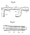
- a second annular nozzle 61 can be provided at the end of the duct 10A, which is fed by a duct 12A.
- it can be provided to divide the air jet of the duct 12, thus realizing (Fig. 6) a jacket 110A around the duct 10A, to form a second nozzle 63.
- the second annular nozzle 61 can even be simply fed by air coming from the outside ; in that case there is no need of the duct 12A.
Landscapes
- Engineering & Computer Science (AREA)
- Textile Engineering (AREA)
- Mechanical Engineering (AREA)
- Treatment Of Fiber Materials (AREA)
- Preliminary Treatment Of Fibers (AREA)
Claims (13)
Applications Claiming Priority (2)
| Application Number | Priority Date | Filing Date | Title |
|---|---|---|---|
| IT948385 | 1985-08-27 | ||
| IT09483/85A IT1187084B (it) | 1985-08-27 | 1985-08-27 | Macchina per lavaggio,rottura e follatura di tessuti,con trascinamento pneumatico |
Publications (2)
| Publication Number | Publication Date |
|---|---|
| EP0215745A1 EP0215745A1 (de) | 1987-03-25 |
| EP0215745B1 true EP0215745B1 (de) | 1989-03-15 |
Family
ID=11130812
Family Applications (1)
| Application Number | Title | Priority Date | Filing Date |
|---|---|---|---|
| EP86830235A Expired EP0215745B1 (de) | 1985-08-27 | 1986-08-27 | Maschine zum Waschen, Brechen und Walken von Geweben durch pneumatisches Einschleppen |
Country Status (7)
| Country | Link |
|---|---|
| US (1) | US4766743A (de) |
| EP (1) | EP0215745B1 (de) |
| CN (1) | CN1018464B (de) |
| DE (1) | DE3662407D1 (de) |
| ES (1) | ES2001579A6 (de) |
| IT (1) | IT1187084B (de) |
| PT (1) | PT83249B (de) |
Cited By (6)
| Publication number | Priority date | Publication date | Assignee | Title |
|---|---|---|---|---|
| EP0312509A1 (de) * | 1987-10-13 | 1989-04-19 | Officina Meccanica Biancalani & C. di Fiorenzo Biancalani & C. S.n.c. | Verfahren und Vorrichtung zum Dämpfen, Brechen, Waschen und Walken von Geweben durch pneumatisches Einschleppen |
| US5678429A (en) * | 1995-01-19 | 1997-10-21 | Zonco Federico & Figlio S.N.C. | Machine for the wet and dry treatment of fabrics in rope or open-width form |
| US5937492A (en) * | 1997-05-09 | 1999-08-17 | Flainox, S.R.L. | Finishing machine with pneumatic entrainment of fabric in strand form |
| EP0535287B2 (de) † | 1991-09-21 | 2001-08-08 | Solipat Ag | Verfahren und Vorrichtung zur Griff- und Oberflächenverbesserung von textilen Geweben und Gewirken |
| DE19813477C2 (de) * | 1998-03-27 | 2001-11-08 | Then Maschinen Und Appbau Gmbh | Verfahren und Vorrichtung zur Behandlung von strangförmigem Textilgut |
| CN104160082A (zh) * | 2012-01-10 | 2014-11-19 | 比安卡拉尼有限公司 | 设置有碰撞构件的织物处理机器 |
Families Citing this family (27)
| Publication number | Priority date | Publication date | Assignee | Title |
|---|---|---|---|---|
| US5014525A (en) * | 1989-10-24 | 1991-05-14 | Madinox S.A. | Machine for dyeing fabric in a rope |
| US5440771A (en) * | 1990-05-14 | 1995-08-15 | S. Sclavos S.A. | Jet dyeing apparatus and method |
| US5299339A (en) * | 1990-05-14 | 1994-04-05 | S. Sclayos S.A. | Jet dyeing apparatus and method |
| DE4119152C2 (de) * | 1991-06-11 | 1993-11-25 | Krantz H Gmbh & Co | Vorrichtung zum Naßbehandeln von Textilgut |
| DE4426336A1 (de) * | 1993-08-23 | 1995-03-02 | Thies Gmbh & Co | Verfahren zur Behandlung einer textilen Warenbahn sowie Vorrichtung zur Durchführung desselben |
| FR2713674B1 (fr) * | 1993-12-10 | 1996-01-12 | Icbt Madinox | Dispositif pour le traitement et l'assouplissement d'une étoffe textile sans fin. |
| US5621937A (en) * | 1994-04-04 | 1997-04-22 | S. Sclavos, S.A. | Jet dyeing apparatus and method |
| US5577282A (en) * | 1995-05-22 | 1996-11-26 | Gaston County Dyeing Machine Company | Textile wet processing machine and method |
| US5713223A (en) * | 1995-08-30 | 1998-02-03 | Lin; Teng Chi | Dyeing machine with reversible dye spouter |
| US5893933A (en) * | 1996-05-23 | 1999-04-13 | Solipat Ag | Device and method for the continuous fulling of a material web of textile woven fabrics and knitted fabrics |
| FR2778417B1 (fr) * | 1998-05-05 | 2000-12-22 | Alliance Machines Textiles | Machine de traitement au mouille en boyau |
| IT1305000B1 (it) * | 1998-09-17 | 2001-04-05 | Flainox Srl | Procedimento e macchina per il finissaggio di tessuto. |
| IT1304999B1 (it) * | 1998-09-17 | 2001-04-05 | Flainox Srl | Macchina per il finissaggio di tessuto. |
| IT1314963B1 (it) * | 2000-06-21 | 2003-01-21 | Biancalani F & C Off Mec | Macchina per il trattamento in continuo di un tessuto |
| ITFI20010168A1 (it) * | 2001-09-12 | 2003-03-12 | Coramtex Srl | Macchina e metodo per il trattamento in continuo di un tessuto |
| DE10349374B4 (de) * | 2003-10-21 | 2009-04-09 | Then Maschinen (B.V.I.) Ltd., Road Town | Nassbehandlungsmaschine für strangförmiges Textilgut |
| BRPI0619973B1 (pt) * | 2005-12-16 | 2018-07-10 | Southern Mills, Inc. | Método para produzir um tecido termicamente protetor, tecido termicamente protetor e métodos para aumentar a proteção térmica por uma vestimenta termicamente protetora. |
| DE102007036408B3 (de) | 2007-08-02 | 2008-12-18 | Then Maschinen Gmbh | Vorrichtung zum Behandeln von strangförmiger Textilware |
| ITFI20070197A1 (it) | 2007-09-04 | 2009-03-05 | Coramtex Srl | "macchina e metodo per il trattamento in continuo di tessuti in corda" |
| ITFI20070198A1 (it) | 2007-09-04 | 2009-03-05 | Coramtex Srl | "macchina per il trattamento di tessuto con un tamburo ruotante attorno ad un asse non parallelo all'asse geometrico del tamburo" |
| WO2009157883A1 (en) * | 2008-06-23 | 2009-12-30 | Canlar Makina Sanayi Ve Ticaret Limited Sirketi | Fabric dyeing machine having full-scale inner drum which doesn't contain fabric carrying pipe |
| CN101798740B (zh) * | 2010-03-31 | 2012-08-01 | 泰安康平纳机械有限公司 | 多功能缩绒柔软整理机 |
| ITFI20120096A1 (it) * | 2012-05-18 | 2013-11-19 | Coramtex Srl | "linea di trattamento per far rientrare e voluminizzare un tessuto e relativo metodo di trattamento di un tessuto" |
| US20190289374A1 (en) | 2012-08-02 | 2019-09-19 | Joseph L. Vilella | Mutually secure optical data network and method |
| CN103757782B (zh) * | 2013-12-27 | 2016-05-04 | 浙江百盛实业有限公司 | 羊毛缩绒、揉搓、卷绕一体化装置 |
| CN103952891A (zh) * | 2014-04-18 | 2014-07-30 | 吴江市科时达纺织有限公司 | 一种织物的整理装置 |
| CN109844208B (zh) | 2016-08-04 | 2021-10-29 | Pvh公司 | 免烫织物和服装及其整理方法 |
Family Cites Families (11)
| Publication number | Priority date | Publication date | Assignee | Title |
|---|---|---|---|---|
| US3718012A (en) * | 1970-09-21 | 1973-02-27 | M Vinas | Device for the wet treatment of textile materials |
| US3685325A (en) * | 1971-04-27 | 1972-08-22 | Synalloy Corp | Apparatus for liquid treatment of textile material webs |
| US3952558A (en) * | 1973-03-28 | 1976-04-27 | Avesta Jernverks Aktiebolag | Machine for dyeing or other wet-treatment of textiles |
| TR18620A (tr) * | 1974-05-04 | 1977-05-13 | Thies A Jun | Uzun serit seklindeki dokuma staihlarinin muamelesine mahsus usul ve tertibat |
| FR2317407A1 (fr) * | 1975-07-07 | 1977-02-04 | Textile Processing Ab | Dispositif partiellement noye pour le traitement au mouille des matieres textiles en boyau |
| US4129017A (en) * | 1977-01-27 | 1978-12-12 | Burlington Industries, Inc. | Lab sample jet dyeing machine |
| GB2031969B (en) * | 1978-10-18 | 1983-03-09 | Hisaka Works Ltd | Jet treatment of textiles |
| DE2908888A1 (de) * | 1979-03-07 | 1980-09-18 | Thies Kg | Verfahren und vorrichtung zur oberflaechenbehandlung endloser textilgebilde |
| IT1135149B (it) * | 1981-01-23 | 1986-08-20 | Attilio Bertoldi | Macchina per la follatura,lavaggio e pre-asciugatura di tessuti in corda |
| US4570404A (en) * | 1983-03-07 | 1986-02-18 | Knudson Gary Art | Two-part hold-down apparatus with slip joint for seamed panel assemblies |
| US4545221A (en) * | 1983-07-21 | 1985-10-08 | Burlington Industries, Inc. | Adjustment and cleaning of the venturi gap in a dyeing machine |
-
1985
- 1985-08-27 IT IT09483/85A patent/IT1187084B/it active
-
1986
- 1986-08-25 US US06/900,360 patent/US4766743A/en not_active Expired - Lifetime
- 1986-08-25 CN CN86105196A patent/CN1018464B/zh not_active Expired
- 1986-08-25 ES ES8601328A patent/ES2001579A6/es not_active Expired
- 1986-08-25 PT PT83249A patent/PT83249B/pt not_active IP Right Cessation
- 1986-08-27 EP EP86830235A patent/EP0215745B1/de not_active Expired
- 1986-08-27 DE DE8686830235T patent/DE3662407D1/de not_active Expired
Cited By (6)
| Publication number | Priority date | Publication date | Assignee | Title |
|---|---|---|---|---|
| EP0312509A1 (de) * | 1987-10-13 | 1989-04-19 | Officina Meccanica Biancalani & C. di Fiorenzo Biancalani & C. S.n.c. | Verfahren und Vorrichtung zum Dämpfen, Brechen, Waschen und Walken von Geweben durch pneumatisches Einschleppen |
| EP0535287B2 (de) † | 1991-09-21 | 2001-08-08 | Solipat Ag | Verfahren und Vorrichtung zur Griff- und Oberflächenverbesserung von textilen Geweben und Gewirken |
| US5678429A (en) * | 1995-01-19 | 1997-10-21 | Zonco Federico & Figlio S.N.C. | Machine for the wet and dry treatment of fabrics in rope or open-width form |
| US5937492A (en) * | 1997-05-09 | 1999-08-17 | Flainox, S.R.L. | Finishing machine with pneumatic entrainment of fabric in strand form |
| DE19813477C2 (de) * | 1998-03-27 | 2001-11-08 | Then Maschinen Und Appbau Gmbh | Verfahren und Vorrichtung zur Behandlung von strangförmigem Textilgut |
| CN104160082A (zh) * | 2012-01-10 | 2014-11-19 | 比安卡拉尼有限公司 | 设置有碰撞构件的织物处理机器 |
Also Published As
| Publication number | Publication date |
|---|---|
| DE3662407D1 (en) | 1989-04-20 |
| CN86105196A (zh) | 1987-03-04 |
| IT8509483A0 (it) | 1985-08-27 |
| PT83249A (en) | 1986-09-01 |
| IT1187084B (it) | 1987-12-16 |
| ES2001579A6 (es) | 1988-06-01 |
| CN1018464B (zh) | 1992-09-30 |
| US4766743A (en) | 1988-08-30 |
| EP0215745A1 (de) | 1987-03-25 |
| PT83249B (pt) | 1992-10-30 |
Similar Documents
| Publication | Publication Date | Title |
|---|---|---|
| EP0215745B1 (de) | Maschine zum Waschen, Brechen und Walken von Geweben durch pneumatisches Einschleppen | |
| FI66948C (fi) | System foer torrformning av papper eller annat arkmaterial av partiklar eller fibrer | |
| US4365424A (en) | Method for surface treatment of an endless textile structure | |
| EP1425454B1 (de) | Maschine und verfahren zur kontinuierlichen behandlung eines gewebes | |
| US11767624B2 (en) | Jet suction box and jet suction process | |
| US3157440A (en) | Fibrous raw material feeding arrangements for spinning machines | |
| US6269550B1 (en) | Drying machine for shredded tobacco, in particular for rolls of expanded shredded tobacco | |
| US4468937A (en) | Machine for the fulling and washing of cord fabrics | |
| US3144187A (en) | Thread conveyor | |
| US3979930A (en) | Method and an apparatus for treating textile materials | |
| US4083208A (en) | Apparatus for the wet treatment of textiles | |
| US3987517A (en) | Pneumatic dust collecting system for fiber processing machine | |
| US2141578A (en) | Conveyer for drying plants | |
| US3375539A (en) | Traveling overhead textile machine cleaner | |
| KR100282783B1 (ko) | 미립자 물질로부터 무거운 입자를 분리하는 방법 및 장치(method and device for separating heavy particles from a particulate material) | |
| US2828552A (en) | Paper drying machine | |
| US3321251A (en) | Apparatus for pneumatically conveying fibrous material | |
| US3943596A (en) | Cleaning of textile carding machines | |
| US3374118A (en) | Floor cleaning method for textile mills | |
| US2597490A (en) | Apparatus for treating textile materials | |
| US2834061A (en) | Pneumatic fiber cleaning apparatus | |
| US4083207A (en) | Apparatus for the wet treatment of textile materials | |
| US2813306A (en) | Apparatus for removing dust and granular material from asbestos fibre | |
| US2136506A (en) | Cotton-gin condenser | |
| NZ197566A (en) | Wool cleaning apparatus:debris passes through grille of axially rotatable rods |
Legal Events
| Date | Code | Title | Description |
|---|---|---|---|
| PUAI | Public reference made under article 153(3) epc to a published international application that has entered the european phase |
Free format text: ORIGINAL CODE: 0009012 |
|
| AK | Designated contracting states |
Kind code of ref document: A1 Designated state(s): BE CH DE FR GB LI |
|
| 17P | Request for examination filed |
Effective date: 19870520 |
|
| 17Q | First examination report despatched |
Effective date: 19880607 |
|
| GRAA | (expected) grant |
Free format text: ORIGINAL CODE: 0009210 |
|
| AK | Designated contracting states |
Kind code of ref document: B1 Designated state(s): BE CH DE FR GB LI |
|
| REF | Corresponds to: |
Ref document number: 3662407 Country of ref document: DE Date of ref document: 19890420 |
|
| ET | Fr: translation filed | ||
| PLBE | No opposition filed within time limit |
Free format text: ORIGINAL CODE: 0009261 |
|
| STAA | Information on the status of an ep patent application or granted ep patent |
Free format text: STATUS: NO OPPOSITION FILED WITHIN TIME LIMIT |
|
| 26N | No opposition filed | ||
| REG | Reference to a national code |
Ref country code: GB Ref legal event code: IF02 |
|
| PGFP | Annual fee paid to national office [announced via postgrant information from national office to epo] |
Ref country code: CH Payment date: 20050810 Year of fee payment: 20 |
|
| PGFP | Annual fee paid to national office [announced via postgrant information from national office to epo] |
Ref country code: FR Payment date: 20050819 Year of fee payment: 20 |
|
| PGFP | Annual fee paid to national office [announced via postgrant information from national office to epo] |
Ref country code: GB Payment date: 20050824 Year of fee payment: 20 Ref country code: BE Payment date: 20050824 Year of fee payment: 20 |
|
| PGFP | Annual fee paid to national office [announced via postgrant information from national office to epo] |
Ref country code: DE Payment date: 20051020 Year of fee payment: 20 |
|
| PG25 | Lapsed in a contracting state [announced via postgrant information from national office to epo] |
Ref country code: GB Free format text: LAPSE BECAUSE OF EXPIRATION OF PROTECTION Effective date: 20060826 |
|
| REG | Reference to a national code |
Ref country code: GB Ref legal event code: PE20 |
|
| REG | Reference to a national code |
Ref country code: CH Ref legal event code: PL |
|
| BE20 | Be: patent expired |
Owner name: *CORMATEX S.R.L. Effective date: 20060827 Owner name: *OFFICINA MECCANICA BIANCALANI & C. DI FIORENZO BI Effective date: 20060827 |