EP0215744A1 - Rollschuh mit einer Fersenriemen-Bindung - Google Patents
Rollschuh mit einer Fersenriemen-Bindung Download PDFInfo
- Publication number
- EP0215744A1 EP0215744A1 EP86830183A EP86830183A EP0215744A1 EP 0215744 A1 EP0215744 A1 EP 0215744A1 EP 86830183 A EP86830183 A EP 86830183A EP 86830183 A EP86830183 A EP 86830183A EP 0215744 A1 EP0215744 A1 EP 0215744A1
- Authority
- EP
- European Patent Office
- Prior art keywords
- slide
- frame
- strap
- skate
- skate according
- Prior art date
- Legal status (The legal status is an assumption and is not a legal conclusion. Google has not performed a legal analysis and makes no representation as to the accuracy of the status listed.)
- Granted
Links
- 101000845183 Homo sapiens Tetratricopeptide repeat protein 5 Proteins 0.000 title 1
- 102100031280 Tetratricopeptide repeat protein 5 Human genes 0.000 title 1
- 238000006073 displacement reaction Methods 0.000 claims description 4
- 210000002683 foot Anatomy 0.000 description 18
- 210000003423 ankle Anatomy 0.000 description 3
- 238000000034 method Methods 0.000 description 3
- 230000000994 depressogenic effect Effects 0.000 description 2
- 238000004873 anchoring Methods 0.000 description 1
- 230000000386 athletic effect Effects 0.000 description 1
- 230000014759 maintenance of location Effects 0.000 description 1
- 238000004904 shortening Methods 0.000 description 1
Images


Classifications
-
- A—HUMAN NECESSITIES
- A63—SPORTS; GAMES; AMUSEMENTS
- A63C—SKATES; SKIS; ROLLER SKATES; DESIGN OR LAYOUT OF COURTS, RINKS OR THE LIKE
- A63C17/00—Roller skates; Skate-boards
- A63C17/02—Roller skates; Skate-boards with wheels arranged in two pairs
-
- A—HUMAN NECESSITIES
- A63—SPORTS; GAMES; AMUSEMENTS
- A63C—SKATES; SKIS; ROLLER SKATES; DESIGN OR LAYOUT OF COURTS, RINKS OR THE LIKE
- A63C1/00—Skates
- A63C1/18—Skates fastened by means of straps
-
- A—HUMAN NECESSITIES
- A63—SPORTS; GAMES; AMUSEMENTS
- A63C—SKATES; SKIS; ROLLER SKATES; DESIGN OR LAYOUT OF COURTS, RINKS OR THE LIKE
- A63C17/00—Roller skates; Skate-boards
- A63C17/0086—Roller skates adjustable in length to fit the size of the foot
-
- A—HUMAN NECESSITIES
- A63—SPORTS; GAMES; AMUSEMENTS
- A63C—SKATES; SKIS; ROLLER SKATES; DESIGN OR LAYOUT OF COURTS, RINKS OR THE LIKE
- A63C17/00—Roller skates; Skate-boards
- A63C17/26—Roller skates; Skate-boards with special auxiliary arrangements, e.g. illuminating, marking, or push-off devices
- A63C17/262—Roller skates; Skate-boards with special auxiliary arrangements, e.g. illuminating, marking, or push-off devices with foot bindings or supports therefor
-
- A—HUMAN NECESSITIES
- A63—SPORTS; GAMES; AMUSEMENTS
- A63C—SKATES; SKIS; ROLLER SKATES; DESIGN OR LAYOUT OF COURTS, RINKS OR THE LIKE
- A63C2203/00—Special features of skates, skis, roller-skates, snowboards and courts
- A63C2203/48—Roller or ice skates adjustable in width
-
- Y—GENERAL TAGGING OF NEW TECHNOLOGICAL DEVELOPMENTS; GENERAL TAGGING OF CROSS-SECTIONAL TECHNOLOGIES SPANNING OVER SEVERAL SECTIONS OF THE IPC; TECHNICAL SUBJECTS COVERED BY FORMER USPC CROSS-REFERENCE ART COLLECTIONS [XRACs] AND DIGESTS
- Y10—TECHNICAL SUBJECTS COVERED BY FORMER USPC
- Y10T—TECHNICAL SUBJECTS COVERED BY FORMER US CLASSIFICATION
- Y10T24/00—Buckles, buttons, clasps, etc.
- Y10T24/21—Strap tighteners
- Y10T24/2175—Cargo tie down
-
- Y—GENERAL TAGGING OF NEW TECHNOLOGICAL DEVELOPMENTS; GENERAL TAGGING OF CROSS-SECTIONAL TECHNOLOGIES SPANNING OVER SEVERAL SECTIONS OF THE IPC; TECHNICAL SUBJECTS COVERED BY FORMER USPC CROSS-REFERENCE ART COLLECTIONS [XRACs] AND DIGESTS
- Y10—TECHNICAL SUBJECTS COVERED BY FORMER USPC
- Y10T—TECHNICAL SUBJECTS COVERED BY FORMER US CLASSIFICATION
- Y10T74/00—Machine element or mechanism
- Y10T74/21—Elements
- Y10T74/2164—Cranks and pedals
- Y10T74/2168—Pedals
- Y10T74/217—Pedals with toe or shoe clips
Definitions
- the present invention relates to a roller skate with a binding device for releasably securing a shod foot to a skate frame.
- Roller skates and especially those intended for recreational non-athletic use, are adapted for removable fastening to user's footwear.
- binding devices of various description generally including a strap.
- skates comprise a frame, mostly extendible to fit different footwear sizes, to which respective straps are attached at the toe and ankle of the user's foot which tighten the foot down against the frame and rearward against a specially provided vertical back wall, the so-called heel- piece.
- Each strap is split into two half-straps respectively attached to the frame on right-hand and left-hand sides; one half-strap is hooked to the other, and concurrently tightened, by means of buckle devices, or tightening or the like devices.
- skates of the type just described are not devoid of drawbacks, especially as relates to their convenience, ease of securement and tightening firmness.
- fasten a skate on one must first unfasten the straps, rest with his/her foot on the skate, fasten the straps, tighten and adjust them finding the most appropriate tension therefor. All these operations are mostly to be repeated each time that the skate is put on, because on releasing the skate, the previously found adjustment is Lost. Then, the inconvenient tensioning procedure reflects unavoidably on its effectiveness.
- skates are not invariably satisfactory; in case of tighter requirements, the user usually chooses directly skates of the competition types having the piece of footwear formed integrally with the skate or permanently attached thereto.
- a roller skate of the aforesaid type characterized in that it comprises a strap arranged arcuately across the frame and adapted for rear fitting, said strap having juxtaposed end portions adjustably associated with the frame, a tensioning means on said frame for applying removably a pull force to said strap end portions, to thereby tighten it on the foot, and releasable locking means for retaining the tensioned condition of said strap.
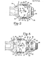
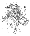
- a roller skate 1 comprises a frame 2 of the extendible kind, comprising a rear half-frame 3 guided slidingly in a longitudinal direction with respect to a forward half-frame 4, by means of a portion 5 of the half-frame 3 being engaged slidingly in a longitudinal seat 6 formed in the half-frame 4 and covered at the top by a plate 7.
- a locking means is provided for removably securing together the two half-frames 3 and 4, e.g. a bolt 19.
- the skate 1 comprises a binding device for securing the foot to the frame 2 at the ankle.
- That binding device comprises a continuous strap 10 arranged substantially arcuately across the frame 2 and provided with juxtaposed end portions 11, adjustably associated with the frame 2 and intended to undergo a pull force to be applied from a tensioning means.
- the tensioning means comprises a slide 13 guided slidingly in the frame 2 in a longitudinal direction to the skate 1; more specifically, the slide 13 is substantially plate-like and movable in a seat 14, formed in the half-frame 3 and covered at the top by a cover plate 15, fastened to the half-frame 3 by a screw 16 passed through an opening 17 in the slide 13.
- the plate 15 has on the rear two upwardly projecting elevations 18 forming abutment seats for a piece of footwear.
- the slide 13 is guided, for example, by a lower contour grooved track 8 in engagement with a respective conforming contour track in the seat 14.
- the slide 13 is connected drivingly, through a drive means, to the end portions 11 for application of the aforesaid pull force thereto, as explained hereinafter.
- two vertical throughgoing seats 20 are formed in the half-frame 3; the seats 20 are open to the seat 14 and extend from top to bottom throughout the half-frame 3 in an oblique direction upward and forward. Inserted through the seats 20 are the end portions 11 of the strap 10. The throughgoing seats 20 prevent any displacement of the strap 10 in the longitudinal direction.
- the aforesaid drive means comprises two cam guides 21 formed laterally on the slide 13, one on each side thereof, and two counter-guides 22 formed on the strap 10, one on each end portion 11.
- the cam guides 21 and counter-guides 22 are in mutual engagement and so shaped that a forward sliding movement of the slide 13 results in a downward sliding movement of the end portions 11.
- the cam guides 21 and counter-guides 22 are straight parallel ribs formed on the slide 13 and on the end portions 11 of the strap 10, and being set at an angle to the longitudinal sliding direction of the slide 13, such ribs are spaced apart from each other by a distance substantially equal to the width of a single rib.
- the slide 13, moreover, is provided with two depressed side areas 23, flanking the cam guides 21.
- the binding device for the skate 1 further comprises means of shifting the slide 13 in the seat 14.
- Such means comprises a plate-like lever journalled rearward of the half-frame 3 by a horizontal pivot 25.
- the lever 24 has a T-shaped groove 26 in which a T-shaped head 27 rigid with the slide 13 is engaged slidingly.
- the lever 24 is provided with locking means wherein a movable handgrip 28 pulls out of respective seats 29 in the half-frame 3, against springs 30, two pins 31, guided slidingly in holes 32 in the lever 24.
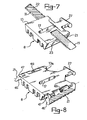
- two horizontal throughgoing seats 34 are formed in the half-frame 4 on either sides of the seat 6 and open to it.
- Juxtaposed end portions 36 of a strap 38 are inserted through the seats 34, each portion 36 being provided with a respective head 39.
- the heads 39 of the end portions 36 have respective counter-guides 41 in engagement with corresponding cam guides 43 formed on top of the portion 5 of the half-frame 3.
- the cam guides 43 and counter-guides 41 are shaped such that a forward sliding movement of the portion 5 (that is, shortening of the skate 1) brings about an inwardly directed sliding movement of the end portions 36 of the strap 38; thus, therefore, the strap 38 forms a seat for the foot toe end, which is made widcr on extending the skate 1 and vice versa, affording automatic accomodation of different size feet.
- the cam guides 43 and counter-guides 41 comprise, similarly to the guides 21 and the counter-guides 22, each a plurality of straight parallel ribs, spaced apart by a distance substantially equal to the width of a single rib and being set at an angle to the longitudinal sliding direction of the half-frames 3 and 4 relatively each other.
- the skate 1 herein and its foot binding device operate as follows.
- Adjustement of the binding tension is possible, when the skate I is in slackened condition; the user can lower the lever 24 further down until the counter-guides 22 and the end portions 11 disengage from the cam guides 21 on the slide 13 and locate themselves in front of the depressed areas 23. In this condition, the user can shift the strap 10 by hand as required; thereafter, the user will again raise the lever 24 partway to restore the engaged condition of the cam guides 21 with the counter-guides 22.
- a skate according to the invention affords quick binding features in a simple and effortless way by putting the skate on from the rear. While rapidity and simplicity are self-evident features that command no explanations, as regards limitation of the effort involved in the binding process, it should be pointed out that whereas with prior skates the binding tension is to be applied directly to the strap axially thereto, with the inventive skate tension is applied through a convenient lever, with a mechanical advantage (determined by the angle of inclination of the cam guides) which is selected to make the fastening procedure as convenient as feasible.
- the rear entrance feature enables the the skate to be put on like any sport footwear, with a very simple movement and using one hand.
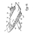
- a slide 13a is shown which is interchangeable with the slide 13; similar parts of the slide 13a to the corresponding parts of the slide 13 are designated in the figure with the same numerals, and will not be described.
- the cam guides 21 (again consisting of straight paralles ribs set at an angle) are formed on two wings 46, pivotally attached to the slide 13a by horizontal and longitudinal side pivots 47, and urged elastically upwards and outwards by torsion springs 48.
- FIG. 12 A variant embodiment of the skate 1 is shown in Figures 12 and 13.
- a slide 50 is guided slidingly in a longitudinal direction in a seat 51 formed longitudinally in a frame 52 of a roller skate 53 (only partly shown).
- the seat 51 is covered at the top by a plate 54.
- Two throughgoing horizontal seats 55 are formed in the frame 52 laterally of the seat 52, and open to it. Two end portions 57 of a strap 58 are inserted into the seats 55 and engage with the slide 50 in a manner to be explained.
- the slide 50 has a plate-like configuration and is provided at the top and bottom with cam guides 59 in engagement with respective counter-guides 60 on the end portions 57 of the strap 58, which sandwich the slide 50 therebetween.
- the cam guides 59 and counter-guides 60 are shaped such that a forward sliding movement of the slide 50 results in an outward sliding movement of the end portions 57; cam guides 59 are straight parallel ribs spaced apart by a distance substantially equal to the width of a single rib and set at an angle to the longitudinal sliding direction of the slide 50.
- a rear lever 61 is provided which is connected to the slide 50 by a cogged belt 62, attached to a forward tip 63 of the slide 50 by means of rivets 64 and being passed below the slide 50 and the end portions 57 of the strap 58; the cogged belt 62 is attached adjustably to the lever 61 by means of a conventional device (not shown), e.g. of the tightening variety.
- the operation of the skate 53 is quite similar to that of the skate 1; the binding tension is adjusted by shifting the cogged belt 62 relatively to the lever 61.
- cam guides and respective counter-guides may take different forms from the ribs herein described and illustrated.
- the counter-guides may be pegs engaging in guides in the form of grooves.
- a skate 65 is partly shown wherein the tensioning means for a strap 66 on a frame 67 comprises two cable lengths 68 anchored on juxtaposed end portions 69 of the strap 66 by means of respective enlarged terminals 70, attached to the cables 68 and being held in respective slots 71 formed in the end portions 69.
- each end portion 69 has several slots 71, for improved adjustement.
- the end portions 69 of the strap 66 are inserted into two respective throughgoing seats 72, formed in the frame 67 and extending through it in an oblique direction upwards and forward.
- the skate 65 further comprises a means of pulling the cables 68, which means comprises a lever 73 carried pivotally rearwards of the frame 67 by a horizontal pivot 74.
- a lever 73 carried pivotally rearwards of the frame 67 by a horizontal pivot 74.
- the lever 73 (configured as a heel piece) there is guided longitudinally a slider 75 having a means of anchoring the lever 73 adjustably, such as a screw 76 carried rotatably on the slider 75 and engaging with a rack 77 formed on the lever 73.
- Anchored on the slider 75 are the cables 68, being passed through side slots 79 and held by enlarged terminals 80.
- the cables 68 extend longitudinally to the lever 73 and are trained around shaped grooves 81 having deflector functions.
- the lever 73 is also provided with a lock device, of a conventional type, not shown in the figures.
- the operation of the skate 65 can be taken directly from the preceding description. To fit the skate on,; the user should lower the lever 73, fit the foot on the frame 67, below the strap 66, and raise the lever 73 back up tightening the strap 66 onto the foot instep, against the heel piece formed by the lever 75 itself.
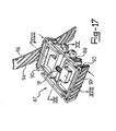
- a futher embodiment of the invention is shown in Figures 16 to 20.
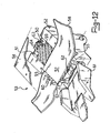
- a skate 82 comprises a frame 83 provided on the rear with an upwardly projecting elevation 84 forming abutment seat for a piece of footwear on the frame 83.
- the skate 82 comprises a binding device for securing the foot to the frame 83 at the ankle.
- That binding device comprises a strap 85, arranged substantially arcuately across the frame 83 and provided with juxtaposed end portions 86, adjustably associated with the frame 83 and intended to undergo a pull force to be applied from a tensioning means.
- the tensioning means comprises a slide 87 guided slidinlgy in the frame 83 in a longitudinal direction to the skate 82 and drivingly connected to the end portions 86 of the strap 85 through a drive means, as explained hereinafter.
- the slide 87 comprises a slide carriage 88, slidable in a seat 89 formed within the frame 83, and two slide wings 90, each slide wing 90 is transversally guided on the slide carriage 88 and a spring 81, compressed between the two slide wings 90, biases the slide wings 90 outwards, one apart from the other.
- two vertical throughgoing seats 92 are formed in the frame 83; the seats 92 are open to the seat 89 and extend from top to bottom throughout the frame 83 in an oblique direction upward and forward. Inserted through the seats 92 are the end portions 86 of the strap 85. The throughgoing seats 92 prevent any displacement of the strap 85 in the longitudinal direction.
- the aforesaid drive means comprises two cam guides 93, each formed on a respective slide wing 90, and two counter-guides 94 formed on the strap 85, one on each end portion 86.
- the cam guides 93 and counter-guides 94 arc in mutual engagement and so shaped that a forward sliding movement of the slide 87 results in a downward sliding movement of the end portions 86.
- the cam guides 93 and the counter-guides 94 are straight parallel ribs formed on the slide wings 90 and the end portions 86 of the strap 85, and being set at an angle to the longitudinal sliding direction of the slide 87 ; such ribs are spaced apart from each other by a distance substantially equal to the width of the single rib.
- Means of shifting the slide 87 in the seat 89 are provided, which means comprises a lever 95 journalled rearward of the frame 83 by a horizontal pivot 96, and a connecting rod 97 journalled to the slide carriage 88 and to the lever'95 by respective horizontal pivots 98 and 99.
- the lever 95 is provided with locking means wherein a push member 100, slidable in a seat 101 in the lever 95 against springs 102, has a hook 103 in a removable engagement with an eye 104 formed on the back of the upwardly projecting elevation 84 of the frame 83.
- the skate 82 herein and its foot binding device operate as follows.
- the user will rest with his/her shod foot on the skate 82 fitting the foot from the rear under the slackened strap 85.
- the piece of footwear will bear rearwardly against the elevation 84.
- Adjustement of the binding tension is possible, when the skate 82 is in slackened condition, by pushing the slide wings 90 by hand and moving the end portions 86 of the strap 85 upwards or downwards.
Landscapes
- Footwear And Its Accessory, Manufacturing Method And Apparatuses (AREA)
- Purses, Travelling Bags, Baskets, Or Suitcases (AREA)
- Buckles (AREA)
Priority Applications (1)
| Application Number | Priority Date | Filing Date | Title |
|---|---|---|---|
| AT86830183T ATE52040T1 (de) | 1985-07-02 | 1986-06-30 | Rollschuh mit einer fersenriemen-bindung. |
Applications Claiming Priority (2)
| Application Number | Priority Date | Filing Date | Title |
|---|---|---|---|
| IT2139785 | 1985-07-02 | ||
| IT21397/85A IT1185163B (it) | 1985-07-02 | 1985-07-02 | Pattino a rotelle con cinturino di allacciatura calzabile da dietro |
Publications (2)
| Publication Number | Publication Date |
|---|---|
| EP0215744A1 true EP0215744A1 (de) | 1987-03-25 |
| EP0215744B1 EP0215744B1 (de) | 1990-04-18 |
Family
ID=11181146
Family Applications (1)
| Application Number | Title | Priority Date | Filing Date |
|---|---|---|---|
| EP86830183A Expired - Lifetime EP0215744B1 (de) | 1985-07-02 | 1986-06-30 | Rollschuh mit einer Fersenriemen-Bindung |
Country Status (7)
| Country | Link |
|---|---|
| US (1) | US4767127A (de) |
| EP (1) | EP0215744B1 (de) |
| JP (1) | JPS628772A (de) |
| AT (1) | ATE52040T1 (de) |
| CA (1) | CA1270013A (de) |
| DE (1) | DE3670450D1 (de) |
| IT (1) | IT1185163B (de) |
Cited By (1)
| Publication number | Priority date | Publication date | Assignee | Title |
|---|---|---|---|---|
| US5678833A (en) * | 1995-06-07 | 1997-10-21 | Rollerblade, Inc. | Adjustable fit in-line skate |
Families Citing this family (14)
| Publication number | Priority date | Publication date | Assignee | Title |
|---|---|---|---|---|
| US4844491A (en) * | 1988-04-08 | 1989-07-04 | J. S. Wheelwright Company, Inc. | Wheeled skate |
| IT213794Z2 (it) * | 1988-06-14 | 1990-03-01 | Duegi Calzaturificio | Puntapiedi anatomico provvisto di una cinghia dentata atta ad esercitare una azione di bloccaggio su entrambi i lati del piede. |
| USD347237S (en) | 1992-03-12 | 1994-05-24 | Fisher-Price, Inc. | Roller skate |
| US6786493B2 (en) * | 2002-01-30 | 2004-09-07 | Shi-Chao Hong | Easily adjusted skate |
| US6851683B2 (en) | 2002-11-04 | 2005-02-08 | Andreas C. Wegener | Adjustable in-line skate |
| TW200500121A (en) * | 2003-02-28 | 2005-01-01 | Reynald Chaput | Low profile roller skate |
| USD493858S1 (en) | 2003-08-25 | 2004-08-03 | Strappers Skates, Inc. | Strap on, size adjustable and full suspension skate |
| JP2005287700A (ja) * | 2004-03-31 | 2005-10-20 | Car Mate Mfg Co Ltd | スノーボード用ビンディング |
| US7516976B2 (en) * | 2005-08-29 | 2009-04-14 | The Burton Corporation | Strap for snowboard boots or bindings |
| US7669880B2 (en) * | 2005-08-29 | 2010-03-02 | The Burton Corporation | Strap for snowboard boots or bindings |
| US7306241B2 (en) * | 2005-08-29 | 2007-12-11 | The Burton Corporation | Strap for snowboard boots or bindings |
| US20120028766A1 (en) * | 2010-07-27 | 2012-02-02 | Thomas Jay Zeek | Weight Lifting Sandals |
| US9713758B2 (en) * | 2013-10-16 | 2017-07-25 | Kevin John LEFSRUD | Ski boot frame |
| USD1105324S1 (en) * | 2023-08-17 | 2025-12-09 | Golabs Inc. | Skate with remote controller |
Citations (7)
| Publication number | Priority date | Publication date | Assignee | Title |
|---|---|---|---|---|
| DE14174C (de) * | P. EVERITT in London | Neuerungen an Schlittschuhen | ||
| DE41072C (de) * | E. ENGELS in Remscheid | Neuerung an Schlittschuhen | ||
| DE137484C (de) * | ||||
| GB2090904A (en) * | 1981-01-14 | 1982-07-21 | Olivieri Icaro & C | Fastener for roller skates |
| FR2514621A1 (fr) * | 1981-10-19 | 1983-04-22 | Salomon & Fils F | Chaussure de ski alpin |
| FR2536290A3 (fr) * | 1982-11-24 | 1984-05-25 | Olivieri Icaro & C | Patin a roulettes du type extensible |
| US4468045A (en) * | 1982-01-12 | 1984-08-28 | Sarazen Philip R | Attachment system for detachable roller skates |
Family Cites Families (4)
| Publication number | Priority date | Publication date | Assignee | Title |
|---|---|---|---|---|
| US31280A (en) * | 1861-01-29 | Skate-fastening | ||
| US283915A (en) * | 1883-08-28 | William j | ||
| US2271452A (en) * | 1941-06-02 | 1942-01-27 | Elbert H Carroll | Ski harness |
| US3693988A (en) * | 1970-02-10 | 1972-09-26 | Paul F Steinhiser | Two wheel roller skate |
-
1985
- 1985-07-02 IT IT21397/85A patent/IT1185163B/it active
-
1986
- 1986-06-25 CA CA000512404A patent/CA1270013A/en not_active Expired - Lifetime
- 1986-06-30 EP EP86830183A patent/EP0215744B1/de not_active Expired - Lifetime
- 1986-06-30 AT AT86830183T patent/ATE52040T1/de not_active IP Right Cessation
- 1986-06-30 DE DE8686830183T patent/DE3670450D1/de not_active Expired - Lifetime
- 1986-07-01 JP JP61152844A patent/JPS628772A/ja active Pending
- 1986-07-02 US US06/881,317 patent/US4767127A/en not_active Expired - Fee Related
Patent Citations (7)
| Publication number | Priority date | Publication date | Assignee | Title |
|---|---|---|---|---|
| DE14174C (de) * | P. EVERITT in London | Neuerungen an Schlittschuhen | ||
| DE41072C (de) * | E. ENGELS in Remscheid | Neuerung an Schlittschuhen | ||
| DE137484C (de) * | ||||
| GB2090904A (en) * | 1981-01-14 | 1982-07-21 | Olivieri Icaro & C | Fastener for roller skates |
| FR2514621A1 (fr) * | 1981-10-19 | 1983-04-22 | Salomon & Fils F | Chaussure de ski alpin |
| US4468045A (en) * | 1982-01-12 | 1984-08-28 | Sarazen Philip R | Attachment system for detachable roller skates |
| FR2536290A3 (fr) * | 1982-11-24 | 1984-05-25 | Olivieri Icaro & C | Patin a roulettes du type extensible |
Cited By (2)
| Publication number | Priority date | Publication date | Assignee | Title |
|---|---|---|---|---|
| US5678833A (en) * | 1995-06-07 | 1997-10-21 | Rollerblade, Inc. | Adjustable fit in-line skate |
| US6050574A (en) * | 1995-06-07 | 2000-04-18 | Rollerblade, Inc. | Adjustable fit in-line skate |
Also Published As
| Publication number | Publication date |
|---|---|
| US4767127A (en) | 1988-08-30 |
| CA1270013A (en) | 1990-06-05 |
| IT8521397A0 (it) | 1985-07-02 |
| ATE52040T1 (de) | 1990-05-15 |
| EP0215744B1 (de) | 1990-04-18 |
| JPS628772A (ja) | 1987-01-16 |
| IT1185163B (it) | 1987-11-04 |
| DE3670450D1 (de) | 1990-05-23 |
Similar Documents
| Publication | Publication Date | Title |
|---|---|---|
| EP0215744B1 (de) | Rollschuh mit einer Fersenriemen-Bindung | |
| US6250651B1 (en) | Adjustable strap | |
| EP1682236B1 (de) | Snowboard-bindungssystem mit automatischer zehenschlaufe | |
| EP0046240B1 (de) | Schlittenkörper und verstellbare Befestigungseinrichtung für Ski | |
| US4620375A (en) | Snowshoe binding and ice crampon or the like | |
| US3061325A (en) | Concealed ski attachment employing reciprocating locking members | |
| US5344179A (en) | Adjustable length binding system for snowboards having independently variable heel and toe spans | |
| US7210252B2 (en) | Step-in snowboard binding and boot therefor | |
| US4190970A (en) | Lever closure for ski boots | |
| US3560014A (en) | Ski pole provided with hand loop | |
| US5918387A (en) | Snowshoe harness | |
| US6279924B1 (en) | Snowboard safety release binding | |
| WO2007084580A2 (en) | Snowshoe binding without heel strap | |
| EP0217750B1 (de) | Vorrichtung zum Befestigen eines Fusses an einem Sportgerät | |
| US6196559B1 (en) | Snowboot binding | |
| EP0434902B1 (de) | Einstellbare Verschlusseinrichtung speziell für Skistiefel | |
| US4050716A (en) | Ski binding | |
| US4109932A (en) | Ski binding of the toe binding type | |
| US3326565A (en) | Long thong safety ski binding having improved turntable means | |
| JP3055942U (ja) | スキービンディング | |
| JPH08299527A (ja) | 固定装置 | |
| CN112237732A (zh) | 一种滑雪板 | |
| AU9331998A (en) | Snowboard safety release binding |
Legal Events
| Date | Code | Title | Description |
|---|---|---|---|
| PUAI | Public reference made under article 153(3) epc to a published international application that has entered the european phase |
Free format text: ORIGINAL CODE: 0009012 |
|
| AK | Designated contracting states |
Kind code of ref document: A1 Designated state(s): AT BE CH DE FR GB IT LI LU NL SE |
|
| 17P | Request for examination filed |
Effective date: 19870218 |
|
| 17Q | First examination report despatched |
Effective date: 19880725 |
|
| GRAA | (expected) grant |
Free format text: ORIGINAL CODE: 0009210 |
|
| AK | Designated contracting states |
Kind code of ref document: B1 Designated state(s): AT BE CH DE FR GB IT LI LU NL SE |
|
| PG25 | Lapsed in a contracting state [announced via postgrant information from national office to epo] |
Ref country code: NL Effective date: 19900418 |
|
| REF | Corresponds to: |
Ref document number: 52040 Country of ref document: AT Date of ref document: 19900515 Kind code of ref document: T |
|
| REF | Corresponds to: |
Ref document number: 3670450 Country of ref document: DE Date of ref document: 19900523 |
|
| ITF | It: translation for a ep patent filed | ||
| ET | Fr: translation filed | ||
| PG25 | Lapsed in a contracting state [announced via postgrant information from national office to epo] |
Ref country code: LU Free format text: LAPSE BECAUSE OF NON-PAYMENT OF DUE FEES Effective date: 19900630 |
|
| NLV1 | Nl: lapsed or annulled due to failure to fulfill the requirements of art. 29p and 29m of the patents act | ||
| PLBE | No opposition filed within time limit |
Free format text: ORIGINAL CODE: 0009261 |
|
| STAA | Information on the status of an ep patent application or granted ep patent |
Free format text: STATUS: NO OPPOSITION FILED WITHIN TIME LIMIT |
|
| 26N | No opposition filed | ||
| PGFP | Annual fee paid to national office [announced via postgrant information from national office to epo] |
Ref country code: AT Payment date: 19930513 Year of fee payment: 8 |
|
| PGFP | Annual fee paid to national office [announced via postgrant information from national office to epo] |
Ref country code: GB Payment date: 19930519 Year of fee payment: 8 |
|
| PGFP | Annual fee paid to national office [announced via postgrant information from national office to epo] |
Ref country code: DE Payment date: 19930524 Year of fee payment: 8 Ref country code: CH Payment date: 19930524 Year of fee payment: 8 |
|
| PGFP | Annual fee paid to national office [announced via postgrant information from national office to epo] |
Ref country code: SE Payment date: 19930526 Year of fee payment: 8 |
|
| PGFP | Annual fee paid to national office [announced via postgrant information from national office to epo] |
Ref country code: BE Payment date: 19930527 Year of fee payment: 8 |
|
| ITTA | It: last paid annual fee | ||
| PGFP | Annual fee paid to national office [announced via postgrant information from national office to epo] |
Ref country code: FR Payment date: 19930630 Year of fee payment: 8 |
|
| PG25 | Lapsed in a contracting state [announced via postgrant information from national office to epo] |
Ref country code: LI Effective date: 19940630 Ref country code: GB Effective date: 19940630 Ref country code: CH Effective date: 19940630 Ref country code: BE Effective date: 19940630 Ref country code: AT Effective date: 19940630 |
|
| PG25 | Lapsed in a contracting state [announced via postgrant information from national office to epo] |
Ref country code: SE Effective date: 19940701 |
|
| BERE | Be: lapsed |
Owner name: ICARO OLIVIERI & C. S.P.A. Effective date: 19940630 |
|
| EUG | Se: european patent has lapsed |
Ref document number: 86830183.9 Effective date: 19950210 |
|
| PG25 | Lapsed in a contracting state [announced via postgrant information from national office to epo] |
Ref country code: FR Effective date: 19950228 |
|
| REG | Reference to a national code |
Ref country code: CH Ref legal event code: PL |
|
| GBPC | Gb: european patent ceased through non-payment of renewal fee |
Effective date: 19940630 |
|
| PG25 | Lapsed in a contracting state [announced via postgrant information from national office to epo] |
Ref country code: DE Effective date: 19950301 |
|
| EUG | Se: european patent has lapsed |
Ref document number: 86830183.9 |
|
| REG | Reference to a national code |
Ref country code: FR Ref legal event code: ST |
|
| PG25 | Lapsed in a contracting state [announced via postgrant information from national office to epo] |
Ref country code: IT Free format text: LAPSE BECAUSE OF NON-PAYMENT OF DUE FEES;WARNING: LAPSES OF ITALIAN PATENTS WITH EFFECTIVE DATE BEFORE 2007 MAY HAVE OCCURRED AT ANY TIME BEFORE 2007. THE CORRECT EFFECTIVE DATE MAY BE DIFFERENT FROM THE ONE RECORDED. Effective date: 20050630 |