EP0215299A2 - Adaptateur pour un alternateur triphasé - Google Patents
Adaptateur pour un alternateur triphasé Download PDFInfo
- Publication number
- EP0215299A2 EP0215299A2 EP86111196A EP86111196A EP0215299A2 EP 0215299 A2 EP0215299 A2 EP 0215299A2 EP 86111196 A EP86111196 A EP 86111196A EP 86111196 A EP86111196 A EP 86111196A EP 0215299 A2 EP0215299 A2 EP 0215299A2
- Authority
- EP
- European Patent Office
- Prior art keywords
- molded part
- outlets
- bolt
- adapter
- axial
- Prior art date
- Legal status (The legal status is an assumption and is not a legal conclusion. Google has not performed a legal analysis and makes no representation as to the accuracy of the status listed.)
- Withdrawn
Links
Images


Classifications
-
- H—ELECTRICITY
- H02—GENERATION; CONVERSION OR DISTRIBUTION OF ELECTRIC POWER
- H02K—DYNAMO-ELECTRIC MACHINES
- H02K5/00—Casings; Enclosures; Supports
- H02K5/04—Casings or enclosures characterised by the shape, form or construction thereof
- H02K5/22—Auxiliary parts of casings not covered by groups H02K5/06-H02K5/20, e.g. shaped to form connection boxes or terminal boxes
- H02K5/225—Terminal boxes or connection arrangements
Definitions
- the invention is based on an adapter according to the preamble of the main claim.
- three-phase generators for making the electrical connections for example with B +, D +, W and the like.
- bolt outlets that extend in the axial direction from a bearing plate, usually extend the B bearing plate and are sometimes also irregularly distributed over this bearing plate.
- the B-end shield is the housing part close to or supporting the brush holder; the drive-side housing part of the three-phase generator is designated as an A-end shield.
- These bolt outlets are usually screw bolts onto which electrical cable connections with eyelet-like end pieces are screwed (see Bosch technical information; three-phase generators for motor vehicles, VDT-UBE 315/30 from December 1970).
- the invention is therefore based on the object of providing an adapter which is capable of converting axial electrical connections, so-called bolt outlets, retained from the outside into radial electrical connections by simple attachment from the outside.
- the adapter according to the invention solves this problem with the characterizing features of the main claim and has the advantage that the adapter can also be retrofitted for converting the bolt outlets from axial to radial even on finished series generators, so that the present generator concepts are not influenced and in particular no intervention in series production is required.
- Such an adapter therefore forms a cost-effective solution as a combination of components and in particular also has advantages with regard to the storage of spare parts.
- the adapter design on which the present invention is based is to be understood as a so-called backpack solution, with the exception of the assembly of the adapter on the respective series generator that all assemblies are also suitable for large series can be manufactured, shaped and assembled.
- Another advantage is the possibility of integrally forming the separate and therefore electrically insulating metallic conductors inserted into the molded part of the adapter in such a way that at the alternator edge they also change into radial bolt outlets, i.e. screw sockets, to which the individual, each with different predetermined threads electrical cables are screwed in the usual way.
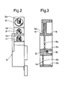
- FIG. 1 shows the adapter in plan view
- FIG. 2 in a view from the left
- FIG. 3 in a sectional view along the line III-III of FIG. 1
- FIG. 4 shows the adapter in the B-end shield of a three-phase generator assembled state
- FIG. 5 shows the representation of FIG. 4 in a side view.
- the adapter formed as a molded part is designated 10; its body forms a first surface 11 in a plane parallel to the drawing plane and a second surface 12 perpendicular to the first surface 11.
- the molded part forming the body of the adapter 10 is, as the side and sectional representations of FIGS. 2 and 3 show, in approximately uniform thickness, and embedded in the plastic material of the molded part are electrical metallic conductors which are insulated from one another and the number of which corresponds to the number of bolt outlets to be converted from axial to radial.
- three electrical connections are to be implemented, namely the connection B +, the connection D + and the connection W, and therefore three electrical outlets 13a, 13b, 13c, which are referred to below as output connections, and which protrude from the surface 12 are preferably formed
- Bolt connections are each with different threads (for example M4, M5 and M6), and in the assembled state on the generator (see FIG. 4), that is when the adapter molded body with its surface 11 opposite and therefore lower on the front side of the B -The bearing plate is screwed, protrude radially from the alternator.
- the three electrical output connections 13a, 13b, 13c are assigned three - or, if more connections are required, a correspondingly larger number - electrical intermediate connections.
- two of these intermediate connections are formed by flat parts 14a, 14b, which are inserted, for example, as flat metallic, preformed and preferably immediately the final shape now shown in the drawings, into the molded part of the adapter, for example during its injection molding production in the mold beforehand inserted and therefore closely encapsulated and enclosed that the intermediate connections can also serve for later attachment of the adapter to the generator.
- the electrically conductive (metallic) flat parts extend through preferably circular clearances 15a, 15b in the molded part and each have a then preferably central through-hole 16a, 16b, which are positioned such that they are in place when the adapter is placed on the three-phase generator Axial bolt outlets located at this point, with which they are then preferably screwed. This will be discussed further below.
- the sheet metal parts then run from the recesses 15a, 15b within the material of the molded part and therefore are electrically insulated and also held securely in each case to the associated further external connection, in this case 13a and 13b, where they are in shape before they exit of bolts a round take shape with flange-like central thickening, collar-like incisions and the like, as can best be seen in the illustration of FIG. 1 in dashed lines and which also results in the firm anchoring in this area in the material of the molded part.
- the inner flat parts forming the intermediate connections do not have to be connected in one-piece transition to the outward-facing round parts, but can also be attached to them later in any manner and connected in an electrically conductive manner.
- the molded part has, where possible, and in addition to the recesses 15a, 15b, through which the axial bolt outlets of the three-phase generator are accessible for screwing, further material thinners, such as the depressions 18, 19 or 20.
- further material thinners such as the depressions 18, 19 or 20.
- the radial bolt outlet 13c is also designed as a round part in the form of the other parts, and thus also has at least one constriction 22 to achieve a tight fit.
- the structure of the adapter 10 is supplemented by the protective caps 27, 28 which close the openings 15a, 15b in the molded body, which are fastened to the adapter body by means of one-piece narrow tags 27a, 28a and of which the protective cap 27 is additionally shown in cross section in FIG. 1a.
- the cone of the protective caps fits the cone of the bores 15a, 15b.
- the three-phase generator designated by 30 in FIGS. 4 and 5 consists of übli cher way from the fan-side A-bearing plate 31 and the slip ring-side B-bearing plate 32, the adapter being normally attached to the B-bearing plate 32 of the alternator 30, since the rectifier diodes are also held on this bearing plate via its own bearing plate and therefore the voltage outputs on it Side are brought out.
- the attachment is made primarily by tightening the nuts on the two axial bolt outlets 29 and 30, which is so secure. clamp the flat parts 14a, 14b of the adapter between them. It may additionally be advantageous to attach narrow limiting strips 33, 34 to the outer end face of the B-end shield 32, as shown in FIG. 4, preferably on both sides of the adapter such that it is laterally fixed and held after being placed on the axial bolt outlets. These narrow retaining strips 33, 34 do not interfere and can therefore be easily provided even with the standard three-phase generator with retained axial bolt outlets.
- radial electrical connection outlets 13a, 13b, 13c can be designed as screw-pin outlets or also as plug-in connections, depending on the requirements.
Landscapes
- Engineering & Computer Science (AREA)
- Power Engineering (AREA)
- Motor Or Generator Frames (AREA)
Applications Claiming Priority (2)
| Application Number | Priority Date | Filing Date | Title |
|---|---|---|---|
| DE19853533065 DE3533065A1 (de) | 1985-09-17 | 1985-09-17 | Adapter fuer einen drehstromgenerator |
| DE3533065 | 1985-09-17 |
Publications (2)
| Publication Number | Publication Date |
|---|---|
| EP0215299A2 true EP0215299A2 (fr) | 1987-03-25 |
| EP0215299A3 EP0215299A3 (fr) | 1988-10-19 |
Family
ID=6281131
Family Applications (1)
| Application Number | Title | Priority Date | Filing Date |
|---|---|---|---|
| EP86111196A Withdrawn EP0215299A3 (fr) | 1985-09-17 | 1986-08-13 | Adaptateur pour un alternateur triphasé |
Country Status (3)
| Country | Link |
|---|---|
| EP (1) | EP0215299A3 (fr) |
| JP (1) | JPS6268037A (fr) |
| DE (1) | DE3533065A1 (fr) |
Cited By (7)
| Publication number | Priority date | Publication date | Assignee | Title |
|---|---|---|---|---|
| FR2629287A3 (fr) * | 1988-03-25 | 1989-09-29 | Equip Electr Moteur | Dispositif a borne de prise de courant pour machine electrique tournante, notamment pour alternateur de vehicule automobile |
| FR2662870A1 (fr) * | 1990-05-29 | 1991-12-06 | Bosch Gmbh Robert | Generateur de courant triphase pour vehicules ou analogues. |
| DE4233679C1 (de) * | 1992-10-07 | 1993-12-02 | Albrecht Knorpp | Elektrische Vielfach-Anschlußeinheit für elektrische Maschinen und Verfahren zu ihrer Herstellung |
| FR2713412A1 (fr) * | 1993-11-29 | 1995-06-09 | Valeo Equip Electr Moteur | Dispositif de raccordement électrique, porte-balais de machine électrique tournante comportant un tel dispositif de raccordement et alternateur de véhicule automobile équipé d'un tel porte-balais. |
| FR2730875A1 (fr) * | 1995-02-21 | 1996-08-23 | Valeo Equip Electr Moteur | Alternateur comportant un capot d'extremite muni d'au moins un capuchon imperdable de protection de bornes de raccordement |
| WO2003071661A1 (fr) * | 2002-02-18 | 2003-08-28 | Siemens Aktiengesellschaft | Unite de fixation destinee a un moteur electrique |
| EP1416613B1 (fr) * | 2002-10-29 | 2018-04-11 | Mitsubishi Denki Kabushiki Kaisha | Machine électrique |
Families Citing this family (3)
| Publication number | Priority date | Publication date | Assignee | Title |
|---|---|---|---|---|
| JPH01113555U (fr) * | 1988-01-21 | 1989-07-31 | ||
| DE19714227A1 (de) * | 1997-04-07 | 1998-10-15 | Walter Soehner Gmbh & Co | Gehäuseteil für eine Lichtmaschine und Lichtmaschine |
| DE102014226128A1 (de) * | 2014-12-16 | 2016-06-16 | Robert Bosch Gmbh | Befestigungsvorrichtung für ein elektrisches Anschlusselement |
Citations (2)
| Publication number | Priority date | Publication date | Assignee | Title |
|---|---|---|---|---|
| GB2064230A (en) * | 1979-11-14 | 1981-06-10 | Sealed Motor Const Co Ltd | Electric motor construction |
| EP0199504A2 (fr) * | 1985-04-10 | 1986-10-29 | Mitsubishi Denki Kabushiki Kaisha | Construction d'une borne pour un générateur à courant alternatif d'un véhicule automobile |
Family Cites Families (3)
| Publication number | Priority date | Publication date | Assignee | Title |
|---|---|---|---|---|
| US2531719A (en) * | 1947-02-14 | 1950-11-28 | Bendix Aviat Corp | Direction determining and reverse operating means |
| DE1052542B (de) * | 1957-02-06 | 1959-03-12 | Siemens Ag | Druckfeste Leitungsdurchfuehrung an Klemmenkaesten fuer elektrische Maschinen |
| DE1891063U (de) * | 1962-07-23 | 1964-04-16 | Fiat Spa | Gleichrichtersatz fuer wechselstromgeneratoren. |
-
1985
- 1985-09-17 DE DE19853533065 patent/DE3533065A1/de active Granted
-
1986
- 1986-08-13 EP EP86111196A patent/EP0215299A3/fr not_active Withdrawn
- 1986-09-16 JP JP21609586A patent/JPS6268037A/ja active Pending
Patent Citations (2)
| Publication number | Priority date | Publication date | Assignee | Title |
|---|---|---|---|---|
| GB2064230A (en) * | 1979-11-14 | 1981-06-10 | Sealed Motor Const Co Ltd | Electric motor construction |
| EP0199504A2 (fr) * | 1985-04-10 | 1986-10-29 | Mitsubishi Denki Kabushiki Kaisha | Construction d'une borne pour un générateur à courant alternatif d'un véhicule automobile |
Cited By (11)
| Publication number | Priority date | Publication date | Assignee | Title |
|---|---|---|---|---|
| FR2629287A3 (fr) * | 1988-03-25 | 1989-09-29 | Equip Electr Moteur | Dispositif a borne de prise de courant pour machine electrique tournante, notamment pour alternateur de vehicule automobile |
| FR2662870A1 (fr) * | 1990-05-29 | 1991-12-06 | Bosch Gmbh Robert | Generateur de courant triphase pour vehicules ou analogues. |
| DE4233679C1 (de) * | 1992-10-07 | 1993-12-02 | Albrecht Knorpp | Elektrische Vielfach-Anschlußeinheit für elektrische Maschinen und Verfahren zu ihrer Herstellung |
| FR2713412A1 (fr) * | 1993-11-29 | 1995-06-09 | Valeo Equip Electr Moteur | Dispositif de raccordement électrique, porte-balais de machine électrique tournante comportant un tel dispositif de raccordement et alternateur de véhicule automobile équipé d'un tel porte-balais. |
| FR2730875A1 (fr) * | 1995-02-21 | 1996-08-23 | Valeo Equip Electr Moteur | Alternateur comportant un capot d'extremite muni d'au moins un capuchon imperdable de protection de bornes de raccordement |
| CN1061793C (zh) * | 1995-02-21 | 2001-02-07 | 瓦莱奥电机设备公司 | 包括配有至少一个接线端子安全保护盖的端罩的交流电机 |
| WO2003071661A1 (fr) * | 2002-02-18 | 2003-08-28 | Siemens Aktiengesellschaft | Unite de fixation destinee a un moteur electrique |
| US7215050B2 (en) | 2002-02-18 | 2007-05-08 | Siemens Ag | Fixing unit for an electric motor |
| EP1416613B1 (fr) * | 2002-10-29 | 2018-04-11 | Mitsubishi Denki Kabushiki Kaisha | Machine électrique |
| EP2026451B1 (fr) * | 2002-10-29 | 2018-04-11 | Mitsubishi Denki Kabushiki Kaisha | Machine rotative électrique |
| EP2026452B1 (fr) * | 2002-10-29 | 2018-04-11 | Mitsubishi Denki Kabushiki Kaisha | Machine rotative électrique |
Also Published As
| Publication number | Publication date |
|---|---|
| EP0215299A3 (fr) | 1988-10-19 |
| DE3533065A1 (de) | 1987-03-19 |
| DE3533065C2 (fr) | 1993-04-08 |
| JPS6268037A (ja) | 1987-03-27 |
Similar Documents
| Publication | Publication Date | Title |
|---|---|---|
| EP0490896B1 (fr) | Redresseur pour generateurs de courant triphase dans des vehicules | |
| WO1997040510A1 (fr) | Boite de fusibles pour vehicules a moteur | |
| DE2320983A1 (de) | Einspeise- bzw. abnehmevorrichtung fuer stromschienen | |
| DE102016103439B4 (de) | Kontaktstelle eines Flachleiters | |
| EP0215299A2 (fr) | Adaptateur pour un alternateur triphasé | |
| DE102017120725A1 (de) | Entwärmungsvorrichtung für eine elektrische leitung, damit ausgestattete leitungsanordnung und verfahren zum entwärmen einer elektrischen leitung | |
| EP0807328B1 (fr) | Bus d'alimentation | |
| DE19539184C3 (de) | Kontaktelement zur Erzeugung eines elektrischen Kontaktes zwischen Hauptleiter und Abzweigleiter sowie Anschlußklemme mit diesem Kontaktelement | |
| EP0763873B1 (fr) | Dispositif de connexion d'au moins un fil de connexion électrique d'un appareil électrique dan un boítier avec un conducteur de câble électrique externe au boítier | |
| EP0858690A1 (fr) | Dispositif de connexion d'une enveloppe electriquement conductrice d'un cable avec un fil de masse | |
| DE3212848A1 (de) | Verbindungselementaufbau mit einer mehrzahl von kontakten zum elektrischen verbinden von anhaengern oder dergleichen | |
| EP3716408A1 (fr) | Protection flexible contre les contacts pour un raccordement électrique | |
| DE4017208C2 (de) | Drehstromgenerator, z.B. für Fahrzeuge | |
| EP0254226B1 (fr) | Combinaison de fiche et de prise pour la connexion de lampes et d'appareils électriques | |
| EP0285079B1 (fr) | Dispositif de serrage pour la réalisation d'une dérivation sur les conducteurs d'un câble de tension et réalisation d'une telle dérivation | |
| AT405000B (de) | Feldabstandhalter für hochspannungs-freileitungen mit bündelleitern | |
| DE102015205450B4 (de) | Hauptsicherungsbox , mit einer Mehrfachsicherung, zur Befestigung an einer Bordnetz-Batterie eines Kraftfahrzeugs | |
| EP0340700B1 (fr) | Boîtier pour appareils de commutation en série | |
| EP0700586B1 (fr) | Appareil electrique avec dispositif de connexion electrique de deux cables electriques a l'appareil | |
| DE19737426B4 (de) | Steckerbuchse für Mittelspannungs-Schaltanlagen | |
| DE3418665A1 (de) | Transformator-mehrfachanschlussvorrichtung | |
| WO2023166085A1 (fr) | Connexion connecteur et prise de batterie, constituée d'une prise montée sur panneau et d'un connecteur monté sur panneau | |
| EP4049898A1 (fr) | Ensemble de câbles, ainsi que procédé de conception d'un ensemble de câbles | |
| DE1259993B (de) | Anschlussklemme fuer Rundsteueranlagen | |
| EP4152538A1 (fr) | Distributeur de puissance haute tension |
Legal Events
| Date | Code | Title | Description |
|---|---|---|---|
| PUAI | Public reference made under article 153(3) epc to a published international application that has entered the european phase |
Free format text: ORIGINAL CODE: 0009012 |
|
| AK | Designated contracting states |
Kind code of ref document: A2 Designated state(s): DE FR GB IT |
|
| PUAL | Search report despatched |
Free format text: ORIGINAL CODE: 0009013 |
|
| AK | Designated contracting states |
Kind code of ref document: A3 Designated state(s): DE FR GB IT |
|
| STAA | Information on the status of an ep patent application or granted ep patent |
Free format text: STATUS: THE APPLICATION IS DEEMED TO BE WITHDRAWN |
|
| 18D | Application deemed to be withdrawn |
Effective date: 19890420 |
|
| RIN1 | Information on inventor provided before grant (corrected) |
Inventor name: LEMKE, WERNER Inventor name: SOHNLE, RUEDIGER, DIPL.-ING. (FH) |