EP0213084A1 - Stoffdrückerfuss für Nähmaschinen mit einer Schneideinrichtung für ein eingelegtes Band od. dgl. - Google Patents
Stoffdrückerfuss für Nähmaschinen mit einer Schneideinrichtung für ein eingelegtes Band od. dgl. Download PDFInfo
- Publication number
- EP0213084A1 EP0213084A1 EP86830121A EP86830121A EP0213084A1 EP 0213084 A1 EP0213084 A1 EP 0213084A1 EP 86830121 A EP86830121 A EP 86830121A EP 86830121 A EP86830121 A EP 86830121A EP 0213084 A1 EP0213084 A1 EP 0213084A1
- Authority
- EP
- European Patent Office
- Prior art keywords
- elastic band
- lace
- stiff
- knife
- tape
- Prior art date
- Legal status (The legal status is an assumption and is not a legal conclusion. Google has not performed a legal analysis and makes no representation as to the accuracy of the status listed.)
- Granted
Links
- 238000009958 sewing Methods 0.000 title claims abstract description 23
- 229910000831 Steel Inorganic materials 0.000 claims description 4
- 239000010959 steel Substances 0.000 claims description 4
- 238000011144 upstream manufacturing Methods 0.000 claims description 3
- 239000004744 fabric Substances 0.000 description 2
- 230000001771 impaired effect Effects 0.000 description 1
- 238000002347 injection Methods 0.000 description 1
- 239000007924 injection Substances 0.000 description 1
Images
Classifications
-
- D—TEXTILES; PAPER
- D05—SEWING; EMBROIDERING; TUFTING
- D05B—SEWING
- D05B37/00—Devices incorporated in sewing machines for slitting, grooving, or cutting
- D05B37/04—Cutting devices
-
- D—TEXTILES; PAPER
- D05—SEWING; EMBROIDERING; TUFTING
- D05B—SEWING
- D05B29/00—Pressers; Presser feet
- D05B29/06—Presser feet
Definitions
- This invention concerns an improvement in or relating to pressure shoes for sewing machines, and in particular to a pressure shoe provided with a built- in cutting device.
- the pressure shoes presently used for said operation are pressure shoes designed for the passage of the elastic band only, which is tensioned by means of a special device, and cutting of the band at the end of operations is performed by means of a separate cutting device, close to the pressure shoe, nevertheless separate therefrom.
- An object of this invention resides in obviating the aforesaid drawbacks and providing a simple and practical device whereby the elastic band can be cut at a really minimum distance away from the needle, so that a suitable ovelap can be provided together with adequate strength of the seam, also when the latter is tensioned, while the junction that had to be provided is disguised in an optimized way.
- the improvement in or relating to pressure shoes for sewing machines resides in that the subject pressure shoe has incorporated therein an elastic band cutting device, said device being located a short distance away from the sewing needle, which is a minimum distance if compared with the distances currently achievable with the pressure shoes presently used.
- the subject pressure shoe is a normal sewing machine pressure shoe where provision is made on the pressure pad thereof for a slot machined in a direction at right angle to the elastic band feeding direction, and through said slot the elastic band is passed (from the top, above the pressure pad), on the downstream edge of said slot a small stationary cutting block, or counter-knife being provided, while on the upstream edge a movable knife is provided, mounted on a special stationary member, and actuated by suitable means (mechanical, pneumatic and/or the like means); the action of said movable knife against the counterknife stationary cutting edge causing the elastic band to be cut; resilient means being provided to ensure that the necessary pressure is exerted upon said pivoting knife.
- suitable means mechanical, pneumatic and/or the like means
- a further feature of the subject pressure shoe resides in that said pressure shoe is provided, at the design stage, with a small tube or duct wherethrough an air stream is injected to act behind the elastic band when the same is inserted through the feeding and cutting slot, to ease the elastic band through the slot and to position the same against the counter- knife; and with a transverse positioning member for said elastic band, comprising a steel wire member fastened sideways on the counter-knife and projecting downwards therefrom in order to provide a side abutment for said elastic band when passing through and sliding underneath said pressure shoe.
- a further feature of the subject pressure shoe resides in that the cutting of the elastic band by means of the subject device is carried out at a distance of 0.5 to 1.5 cm away from the sewing needle, preferably around about 1 cm.
- the movable knife is designed in the form of a pivoting knife, i.e. comprising a substantially vertical shaft rotatably mounted within a suitable bearing provided on the pressure shoe, and pivotable within said bearing; the base of said pivot shaft being provided with a cutting blade, at right angle to said pivot shaft, then substantially horizontal, which acts as a scissor blade upon the elastic band to be cut, the latter being inserted at that time between said blade and the stationary counter-knife cutter; at the upper end of said pivot shaft there being fastened an essentially horizontal square adtuat- ing member at right angles to said pivot shaft, which is connected at the free end thereof to the actuating means (mechanical, pneumatic and/or the like) provided for actuating said pivoting knife; the resilient means provided to ensure the necessary pressure on the pivoting knife being a coil spring installed between the support member and the blade, concentric to the pivot shaft of the pivoting knife.
- actuating means mechanical, pneumatic and/or the like
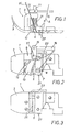
- the subject sewing machine pressure shoe is a substantially conventional pressure shoe 1, wherein a slot 5 is designed to be provided on the pressure pad 3 thereof, in a direction at right angle to the moving direction of elastic band 5' (fig. 1); a stationary cutting block or counterknife 7 being provided on the downstream edge of said slot, while on the upstream edge there is mounted a pivoting knife connected to a suitable stationary support 9 wherein said pivoting knife can rotate with the desired angle.
- Said pivoting knife essentially comprises an upward pivot shaft 11, adapted to rotate, as already said, within the suitable cylindrical seat of stationary support member 9, and at the lower end of said pivot shaft a cutting blade 13 is fastened, at right angle to pivot shaft 11, while at the top end an actuating member 15 is fastened, also at right angle to pivot shaft 11.
- actuating means which can be mechanical, pneumatic, and/or the like, according to what the user desires.
- said means are mechanical means (member 16 connected to actuating member 15).
- the stationary cutter 7 is fastened to the pressure pad 3 through suitable fastening means 17, which are shown as screws in the drawing.
- the stationary support member 9 as well is fastened to pressure pad 3 through suitable fastening means, for instance the screws 19.
- a coil spring 21 which acts upon cutting blade 13, in order to subject said blade to the desired pressure, which is required to cut the elastic band in a proper manner.
- the pressure shoe is provided with a small air injection tube 23, which opens at 25 in slot 5; said air stream provides an easing function for passage of elastic band 5' through said slot, and it provides for positioning the same against cutting block 7.
- steel wire 27 which projects sideways from cutting block 7 and underneath pressure pad 3; said steel wire pin 27 providing an abutment member for the elastic band, in order to avoid drifting thereof from the correct position.
- the elastic band 5' is inserted from above through slot 5 and therefrom it is eased to pass underneath pressured pad 3 according to the normal feed direction thereof (fig. 1).
- the elastic band is tensioned in order to provide for curling of the hem of the garment where the band is being applied.
- the elastic band has to be cut in order to perform the overlap possibly necessary to complete the ring-like fastening thereof.
- said stretch of elastic band free of tension, included between the cut and the intersection point of sewing needle path A with the elastic band (fig. 1) is extremely small, of the order ot about 1 cm, whereby the overlap performed over such a length is absolutely unobtrusive and does not impair quality of the garment.
- the subject pressure shoe besides the application of an elastic band, can be used for sewing a tape of a stiff lace.
Landscapes
- Engineering & Computer Science (AREA)
- Textile Engineering (AREA)
- Sewing Machines And Sewing (AREA)
Applications Claiming Priority (2)
| Application Number | Priority Date | Filing Date | Title |
|---|---|---|---|
| IT8567434A IT1215157B (it) | 1985-05-13 | 1985-05-13 | Perfezionamento a piedini per macchine da cucire |
| IT6743485 | 1985-05-13 |
Publications (2)
| Publication Number | Publication Date |
|---|---|
| EP0213084A1 true EP0213084A1 (de) | 1987-03-04 |
| EP0213084B1 EP0213084B1 (de) | 1989-08-16 |
Family
ID=11302360
Family Applications (1)
| Application Number | Title | Priority Date | Filing Date |
|---|---|---|---|
| EP86830121A Expired EP0213084B1 (de) | 1985-05-13 | 1986-05-12 | Stoffdrückerfuss für Nähmaschinen mit einer Schneideinrichtung für ein eingelegtes Band od. dgl. |
Country Status (3)
| Country | Link |
|---|---|
| EP (1) | EP0213084B1 (de) |
| DE (1) | DE3665083D1 (de) |
| IT (1) | IT1215157B (de) |
Cited By (1)
| Publication number | Priority date | Publication date | Assignee | Title |
|---|---|---|---|---|
| WO2007128364A1 (de) * | 2006-05-05 | 2007-11-15 | Zsk Stickmaschinen Gmbh | Trenn- und positioniereinrichtung |
Citations (5)
| Publication number | Priority date | Publication date | Assignee | Title |
|---|---|---|---|---|
| DE23750C (de) * | NÄHMASCHINENFABRIK JUNKER & RUH in Karlsruhe, Baden | Neuerungen an dem unter Nr. 21818 patentirten Apparat zum Aufnähen von Soutache für Nähmaschinen | ||
| US3468269A (en) * | 1967-05-01 | 1969-09-23 | Frederic P Worthen | Method and apparatus for cutting tape in sewing machine |
| US3648632A (en) * | 1968-11-21 | 1972-03-14 | Quick Service Textiles | Apparatus for feeding and cutting strip material |
| GB1464147A (en) * | 1973-12-27 | 1977-02-09 | Rockwell Rimoldi Spa | Device for cutting and inserting a ribbon underneath the presser foot of a sewing machine |
| GB2060722A (en) * | 1979-09-20 | 1981-05-07 | Rockwell Rimoldi Spa | A sewing machine |
-
1985
- 1985-05-13 IT IT8567434A patent/IT1215157B/it active
-
1986
- 1986-05-12 DE DE8686830121T patent/DE3665083D1/de not_active Expired
- 1986-05-12 EP EP86830121A patent/EP0213084B1/de not_active Expired
Patent Citations (5)
| Publication number | Priority date | Publication date | Assignee | Title |
|---|---|---|---|---|
| DE23750C (de) * | NÄHMASCHINENFABRIK JUNKER & RUH in Karlsruhe, Baden | Neuerungen an dem unter Nr. 21818 patentirten Apparat zum Aufnähen von Soutache für Nähmaschinen | ||
| US3468269A (en) * | 1967-05-01 | 1969-09-23 | Frederic P Worthen | Method and apparatus for cutting tape in sewing machine |
| US3648632A (en) * | 1968-11-21 | 1972-03-14 | Quick Service Textiles | Apparatus for feeding and cutting strip material |
| GB1464147A (en) * | 1973-12-27 | 1977-02-09 | Rockwell Rimoldi Spa | Device for cutting and inserting a ribbon underneath the presser foot of a sewing machine |
| GB2060722A (en) * | 1979-09-20 | 1981-05-07 | Rockwell Rimoldi Spa | A sewing machine |
Cited By (1)
| Publication number | Priority date | Publication date | Assignee | Title |
|---|---|---|---|---|
| WO2007128364A1 (de) * | 2006-05-05 | 2007-11-15 | Zsk Stickmaschinen Gmbh | Trenn- und positioniereinrichtung |
Also Published As
| Publication number | Publication date |
|---|---|
| IT8567434A0 (it) | 1985-05-13 |
| EP0213084B1 (de) | 1989-08-16 |
| DE3665083D1 (en) | 1989-09-21 |
| IT1215157B (it) | 1990-01-31 |
Similar Documents
| Publication | Publication Date | Title |
|---|---|---|
| US5370071A (en) | Lap seamer device for sewing machine | |
| US5394813A (en) | Apparatus for sewing an elastic tape on an edge of a workpiece | |
| EP0213084B1 (de) | Stoffdrückerfuss für Nähmaschinen mit einer Schneideinrichtung für ein eingelegtes Band od. dgl. | |
| US3712256A (en) | Device on sewing machines for guiding the thread chain | |
| US4827857A (en) | Cylindrical bed sewing machine | |
| JPS59209377A (ja) | 針糸の糸ばさみ装置を備えた釦穴かがりミシン | |
| US5197400A (en) | Trimming apparatus for use in making a hem | |
| JPS5944072B2 (ja) | ミシン用加工片トリミング装置 | |
| KR930006497B1 (ko) | 실절단 및 체부장치를 가지는 단추구멍 재봉기 | |
| US4020776A (en) | Feeding and cutting attachment for sewing machines | |
| JP4734010B2 (ja) | ミシン | |
| US2676557A (en) | Apparatus for making piped or bound edgings | |
| US4005663A (en) | Belt loop forming attachment for sewing machine | |
| US4404921A (en) | Buttonhole machine with automatic thread clipping | |
| US2588281A (en) | Fur sewing machine | |
| US5448960A (en) | Binding tape and elastic insertion | |
| US3857346A (en) | Cutting implement for flat-bed sewing machine | |
| US4616582A (en) | Work clamp for buttonhole sewing machines | |
| US3011460A (en) | Material feeding and cutting attachment for sewing machines | |
| US5038691A (en) | Sewing procedure for piping or the like | |
| JPH05192469A (ja) | ラップシームステッチを実行する装置 | |
| US2433053A (en) | Sewing machine | |
| US3054366A (en) | Lapped seam trimmer | |
| US3967568A (en) | Thread cutter for blindstitch sewing machine | |
| JP2568186Y2 (ja) | サージングミシン用生地ガイド |
Legal Events
| Date | Code | Title | Description |
|---|---|---|---|
| PUAI | Public reference made under article 153(3) epc to a published international application that has entered the european phase |
Free format text: ORIGINAL CODE: 0009012 |
|
| AK | Designated contracting states |
Kind code of ref document: A1 Designated state(s): BE DE FR GB NL |
|
| 17P | Request for examination filed |
Effective date: 19870304 |
|
| 17Q | First examination report despatched |
Effective date: 19880502 |
|
| GRAA | (expected) grant |
Free format text: ORIGINAL CODE: 0009210 |
|
| AK | Designated contracting states |
Kind code of ref document: B1 Designated state(s): BE DE FR GB NL |
|
| REF | Corresponds to: |
Ref document number: 3665083 Country of ref document: DE Date of ref document: 19890921 |
|
| ET | Fr: translation filed | ||
| PGFP | Annual fee paid to national office [announced via postgrant information from national office to epo] |
Ref country code: BE Payment date: 19900509 Year of fee payment: 5 |
|
| PGFP | Annual fee paid to national office [announced via postgrant information from national office to epo] |
Ref country code: FR Payment date: 19900516 Year of fee payment: 5 |
|
| PLBI | Opposition filed |
Free format text: ORIGINAL CODE: 0009260 |
|
| PGFP | Annual fee paid to national office [announced via postgrant information from national office to epo] |
Ref country code: NL Payment date: 19900531 Year of fee payment: 5 |
|
| PGFP | Annual fee paid to national office [announced via postgrant information from national office to epo] |
Ref country code: DE Payment date: 19900702 Year of fee payment: 5 |
|
| 26 | Opposition filed |
Opponent name: RIMOLDI S.R.L. Effective date: 19900515 |
|
| PGFP | Annual fee paid to national office [announced via postgrant information from national office to epo] |
Ref country code: GB Payment date: 19900712 Year of fee payment: 5 |
|
| NLR1 | Nl: opposition has been filed with the epo |
Opponent name: RIMOLDI S.R.L. |
|
| PG25 | Lapsed in a contracting state [announced via postgrant information from national office to epo] |
Ref country code: GB Effective date: 19910512 |
|
| PG25 | Lapsed in a contracting state [announced via postgrant information from national office to epo] |
Ref country code: BE Effective date: 19910531 |
|
| BERE | Be: lapsed |
Owner name: RIM-SERVICE TORINO S.R.L. Effective date: 19910531 |
|
| PG25 | Lapsed in a contracting state [announced via postgrant information from national office to epo] |
Ref country code: NL Effective date: 19911201 |
|
| GBPC | Gb: european patent ceased through non-payment of renewal fee | ||
| PLBN | Opposition rejected |
Free format text: ORIGINAL CODE: 0009273 |
|
| STAA | Information on the status of an ep patent application or granted ep patent |
Free format text: STATUS: OPPOSITION REJECTED |
|
| NLV4 | Nl: lapsed or anulled due to non-payment of the annual fee | ||
| PG25 | Lapsed in a contracting state [announced via postgrant information from national office to epo] |
Ref country code: FR Effective date: 19920131 |
|
| 27O | Opposition rejected |
Effective date: 19911010 |
|
| PG25 | Lapsed in a contracting state [announced via postgrant information from national office to epo] |
Ref country code: DE Effective date: 19920303 |
|
| REG | Reference to a national code |
Ref country code: FR Ref legal event code: ST |