EP0212009B1 - Porte enroulable, comportant des lamelles articulées et des rails de guidage dans lesquels les bouts des lamelles sont insérés - Google Patents
Porte enroulable, comportant des lamelles articulées et des rails de guidage dans lesquels les bouts des lamelles sont insérés Download PDFInfo
- Publication number
- EP0212009B1 EP0212009B1 EP85202003A EP85202003A EP0212009B1 EP 0212009 B1 EP0212009 B1 EP 0212009B1 EP 85202003 A EP85202003 A EP 85202003A EP 85202003 A EP85202003 A EP 85202003A EP 0212009 B1 EP0212009 B1 EP 0212009B1
- Authority
- EP
- European Patent Office
- Prior art keywords
- lamellae
- front face
- lamella
- guiding
- wall
- Prior art date
- Legal status (The legal status is an assumption and is not a legal conclusion. Google has not performed a legal analysis and makes no representation as to the accuracy of the status listed.)
- Expired - Lifetime
Links
Images
Classifications
-
- E—FIXED CONSTRUCTIONS
- E06—DOORS, WINDOWS, SHUTTERS, OR ROLLER BLINDS IN GENERAL; LADDERS
- E06B—FIXED OR MOVABLE CLOSURES FOR OPENINGS IN BUILDINGS, VEHICLES, FENCES OR LIKE ENCLOSURES IN GENERAL, e.g. DOORS, WINDOWS, BLINDS, GATES
- E06B9/00—Screening or protective devices for wall or similar openings, with or without operating or securing mechanisms; Closures of similar construction
- E06B9/02—Shutters, movable grilles, or other safety closing devices, e.g. against burglary
- E06B9/08—Roll-type closures
- E06B9/11—Roller shutters
- E06B9/115—Roller shutters specially adapted for furniture
-
- E—FIXED CONSTRUCTIONS
- E06—DOORS, WINDOWS, SHUTTERS, OR ROLLER BLINDS IN GENERAL; LADDERS
- E06B—FIXED OR MOVABLE CLOSURES FOR OPENINGS IN BUILDINGS, VEHICLES, FENCES OR LIKE ENCLOSURES IN GENERAL, e.g. DOORS, WINDOWS, BLINDS, GATES
- E06B9/00—Screening or protective devices for wall or similar openings, with or without operating or securing mechanisms; Closures of similar construction
- E06B9/56—Operating, guiding or securing devices or arrangements for roll-type closures; Spring drums; Tape drums; Counterweighting arrangements therefor
- E06B9/58—Guiding devices
Definitions
- the invention relates to a roller door comprising a number of mutually hingedly connected elongate lamellae and guiding rails positioned at the ends of the lamellae, in which these ends are inserted, said guiding rails extending themselves at a distance from and parallel to each other along the two sides of a door opening and each comprising bends to bring the lamellae outside the plane of the door opening when opening the door, one of said bends connecting two mainly parallel running guiding rail sections, said lamellae having a substantially flat front face such that the front faces of the lamellae substantially link up with each other in the closed position of the door, the hinge parts of each lamellae being connected to said flat front face and being formed by two spaced pivots located behind the front face and near the longitudinal edges thereof and being shaped such that the pivots of succeeding lamellae can be slid into each other, the radius of curvature of the outerwall of said one bend being not more than 25% larger than the width of the front face of the lamellae.
- roller door is known from FR-A-92,783 and in particular from the Figs. 2-4 of it.
- the invention has as'an object to avoid this disadvantage and to provide a construction by which deflection of the lamellae over 180° is possible without the danger of jamming.
- each lamellae is provided with a curved guiding plane being formed between the pivots and behind these, as seen from thefrontface of the lamellae, which guiding plane can cooperate with the inner wall of said one bend of the guiding rails, the leading point of said guiding plane seen in the direction of movement when opening the door, being located farther away from the front face of the lamella than the most rearward point of it, said guiding rail immediately before the beginning of said bend, having a narrowing with a smaller internal width than the preceding part but such that no jamming of the lamellae can occur, the bend joining the narrowing having an increasing width over an angle of about 150°, the radius of curvature of the inner wall of said bend being equal to or smaller than the radius of curvature of the curved guiding plane of the lamellae and the inner wall of said bend of the guiding rails, joining said section bent over about 150°, is passing into the straight section via an only slightly bent section.
- the leading point of the curved guiding plane of the lamellae is spaced further away from the front face of the lamella than the rear point, it is achieved that the guidance of the lamellae mainly occurs by the first mentioned point, whereas only during the returning movement, thus bringing the lamellae towards the closed position, the guiding plane of the lamella cooperates with the inner wall of the bent section of the guiding rail immediately joining the narrowing.
- the radius of this inner wall is therefore equal to or somewhat smaller than the radius of curvature of the curved guiding plane of the lamellae.
- the radius of curvature of the outer wall of the bend does not need to be more than 25% larger than the width of the front face of the lamellae, as a consequence of which the complete bend near the side wall of the cabinet will occupy little space.
- the length of the narrowing of the guiding rail will be about equal to the width of the front face of the lamellae, the narrowing being applied such that the outer wall of the guiding rail describes a straight line.
- the radius of curvature of the inner wall of the bend, immediately joining the narrowing, and the radius of curvature of the guiding plane of the lamellae is about equal to half the width of the front face of the lamellae.
- the dimensions of the bend may be decreased even further when that part of the inner wall of the bend immediately joining the narrowing has the above mentioned radius of curvature over about 90°, while the radius of curvature thereafter is decreased by 15 to 20% over about 60°.
- the radius of curvature of the outer wall of the bend does not have to be more than 12% larger than the width of the front face of a lamella.
- the width of the guiding plane as projected on the front face of the lamella and located behind this is 50 to 60% of the width of the front face of the lamella
- the distance between the leading point of the guiding plane located farthest from the front face and the front face is from 45 to 55% of the width of the front face of the lamella
- the pivot of a lamella present in front of the guiding plane in the direction of movement when opening the door, is constituted by a bent wall section continuing over at least 240° for enclosing a pinshaped part as this has been applied at the other side of a lamella for forming the other part of a pivot.
- a wall section is connected, extending substantially parallel to the front face of the lamella, and being suitable to cooperate with the bent wall section, forming part of a pivot of an adjacent lamella.
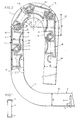
- the lamellae have a substantially flat front face 3, which is for example somewhat corrugated or profiled in order to obtain a specific appearance of the outer face of the door in its closed position.
- Each lamella has a pinshaped pivot 4 and a bent wall portion 5 located opposite it, which together with a pinshaped pivot of a subsequent lamella forms a hinge.
- an enclosing wall portion 6 is provided opposite the pinshaped pivot 4, such that the bent wall portion 5 is between the pinshaped pivot 4 and the enclosing wall portion 6.
- each lamella comprises a curved guiding plane 7, provided in such a way that the leading point 8 of this guiding plane is located farther from the front face 3 of the lamella than the rearward point 9 of the guiding plane.
- the leading point that point is considered that moves in front when the door is slit open.
- the direction of opening is indicated in Fig. 2 with the arrow V.
- the bend 11 is connected in such a way that the subsequent straight section 12 of the rail 2 may run substantially parallel to the side wall of a cabinet.
- the straight section 12 passes via a bent section 13, formed in a special way, into a straight section 14, which may extend up to the vicinity of the straight section 10 of the guiding rail 2.
- the straight section 14 of the guiding rail 2 may make a certain angle with the straight section 12 as appears from Fig. 2.
- Fig. 2 shows a number lamellae in the position as these will approximately occupy on sliding open the door, thus on displacement of the lamellae in the direction of the arrow V, when a force is exerted on the lamellae via an ultimate, specially shaped lamella 1a of the door.
- the guiding rails 2 In order to guide the lamellae 1 in the proper way through the guiding rails 2 the guiding rails 2 have an inner width B, which is larger than the largest thickness D of a lamella 1, such that over the greater part of the path of motion of the lamellae 1 these have a substantial play with respect to the side walls of the rail.
- the straight section 12 of the guiding rail 2 Prior to the beginning of the bent section 13 the straight section 12 of the guiding rail 2 has a narrowed section 15 with a width B1, which is only 4% larger than the thickness D of a lamella 1, while the length of the narrowing is about equal to the width E of the front face 3 of a lamella.
- the lamella 1 is fairly accurately brought into that position, in which the front face 3 of the lamella over its whole width engages the section 16 of the outer wall of the guiding rail just before passing through the bent section 13.
- the lamellae moving in front of the latter mentioned lamella are diverted by the section 17 of the outer wall of the bent section 13, whereby the lamellae 1 B and 1 C are turned over nearly the maximum angle with respect to each other.
- the leading point of the lamella 1C or of a lamella 1D preceding it will engage a nearly straight extending section 18 of the inner wall of the guiding rail 2.
- the lamella 1D is turned back with respect to the lamella 1C, so that for example the front faces of the successive lamellae 1D and 1E will come to ly in one plane again.
- radius R of the outer wall 17 of the bent section 13 has to be only about 12% larger than the width E of the front face of a lamella, so that the turning over of the lamellae over somewhat more than 180° can take place within a very limited space.
- the radius S was substantially equal to the thickness D of a lamella.
- the inner wall 19 of the bent section 13 joining the part with radius S and extending over about 90°, has a radius T which is about 20% smaller than the radius S.
Claims (8)
Priority Applications (1)
| Application Number | Priority Date | Filing Date | Title |
|---|---|---|---|
| AT85202003T ATE52832T1 (de) | 1985-08-13 | 1985-11-29 | Rolltor mit scharnierartig miteinander verbundenen lamellen und fuehrungsschienen in denen die enden der lamellen gefuehrt sind. |
Applications Claiming Priority (2)
| Application Number | Priority Date | Filing Date | Title |
|---|---|---|---|
| NL8502236A NL8502236A (nl) | 1985-08-13 | 1985-08-13 | Jaloeziedeur omvattende scharnierend met elkaar verbonden lamellen en de einden van de lamellen opnemende geleidingsrails. |
| NL8502236 | 1985-08-13 |
Publications (3)
| Publication Number | Publication Date |
|---|---|
| EP0212009A2 EP0212009A2 (fr) | 1987-03-04 |
| EP0212009A3 EP0212009A3 (en) | 1988-03-16 |
| EP0212009B1 true EP0212009B1 (fr) | 1990-05-16 |
Family
ID=19846417
Family Applications (1)
| Application Number | Title | Priority Date | Filing Date |
|---|---|---|---|
| EP85202003A Expired - Lifetime EP0212009B1 (fr) | 1985-08-13 | 1985-11-29 | Porte enroulable, comportant des lamelles articulées et des rails de guidage dans lesquels les bouts des lamelles sont insérés |
Country Status (6)
| Country | Link |
|---|---|
| EP (1) | EP0212009B1 (fr) |
| JP (1) | JPS6241887A (fr) |
| AT (1) | ATE52832T1 (fr) |
| CA (1) | CA1271698A (fr) |
| DE (1) | DE3577737D1 (fr) |
| NL (1) | NL8502236A (fr) |
Cited By (1)
| Publication number | Priority date | Publication date | Assignee | Title |
|---|---|---|---|---|
| CN104234605A (zh) * | 2014-07-14 | 2014-12-24 | 宁波禾采医疗器械有限公司 | 一种卷帘门 |
Families Citing this family (5)
| Publication number | Priority date | Publication date | Assignee | Title |
|---|---|---|---|---|
| FR2646461B1 (fr) * | 1989-04-28 | 1995-05-24 | Marcadet Mobilier | Rideau coulissant a lames articulees, en particulier pour meuble |
| FR2683584B1 (fr) * | 1991-11-12 | 1994-01-07 | Bondet Ets Andre | Profile pour la realisation de volets-rideaux coulissants. |
| DE4336016A1 (de) * | 1993-10-22 | 1995-04-27 | Langer Ruth Geb Layher | Eckverbindungs-Ausbildung |
| CN201071673Y (zh) * | 2007-08-21 | 2008-06-11 | 沈立 | 履带式型材 |
| CN105987128B (zh) * | 2015-03-23 | 2019-11-22 | 清展科技股份有限公司 | 屏幕装置之链条结构及其链接单元件 |
Family Cites Families (4)
| Publication number | Priority date | Publication date | Assignee | Title |
|---|---|---|---|---|
| DE221575C (fr) * | ||||
| GB593961A (en) * | 1945-06-20 | 1947-10-30 | Maurice Henry Robin | Improvements in or relating to roll type closures |
| FR92783E (fr) * | 1960-05-25 | 1968-12-27 | Marcadet Sa Des Atel | Rideau coulissant a lames agrafées en particulier pour meubles. |
| FR2417623A1 (fr) * | 1978-02-20 | 1979-09-14 | Plastil Sa | Lame profilee pour fermeture a rideau munie d'organes d'articulation des lames entre elles avec guidage interieur et exterieur |
-
1985
- 1985-08-13 NL NL8502236A patent/NL8502236A/nl not_active Application Discontinuation
- 1985-11-29 AT AT85202003T patent/ATE52832T1/de not_active IP Right Cessation
- 1985-11-29 DE DE8585202003T patent/DE3577737D1/de not_active Expired - Fee Related
- 1985-11-29 EP EP85202003A patent/EP0212009B1/fr not_active Expired - Lifetime
-
1986
- 1986-02-10 JP JP61026056A patent/JPS6241887A/ja active Pending
- 1986-03-05 CA CA000503367A patent/CA1271698A/fr not_active Expired - Fee Related
Cited By (2)
| Publication number | Priority date | Publication date | Assignee | Title |
|---|---|---|---|---|
| CN104234605A (zh) * | 2014-07-14 | 2014-12-24 | 宁波禾采医疗器械有限公司 | 一种卷帘门 |
| CN104234605B (zh) * | 2014-07-14 | 2016-06-29 | 宁波禾采医疗器械有限公司 | 一种卷帘门 |
Also Published As
| Publication number | Publication date |
|---|---|
| ATE52832T1 (de) | 1990-06-15 |
| NL8502236A (nl) | 1987-03-02 |
| EP0212009A3 (en) | 1988-03-16 |
| CA1271698A (fr) | 1990-07-17 |
| JPS6241887A (ja) | 1987-02-23 |
| DE3577737D1 (de) | 1990-06-21 |
| EP0212009A2 (fr) | 1987-03-04 |
Similar Documents
| Publication | Publication Date | Title |
|---|---|---|
| US5070925A (en) | Security shutter system | |
| US4765027A (en) | Door hinge | |
| JPH0251766B2 (fr) | ||
| EP0212009B1 (fr) | Porte enroulable, comportant des lamelles articulées et des rails de guidage dans lesquels les bouts des lamelles sont insérés | |
| US3554267A (en) | Folding doors | |
| EP0844357B1 (fr) | Porte sectionnelle pourvue d'un joint de protection entre paneaux voisines | |
| CN114223317A (zh) | 多设备箱体的安装装置、包括这种安装装置的安装框架以及包括这种安装框架和多设备箱体的多设备装置 | |
| EP0170338B1 (fr) | Porte enroulable, volet enroulable ou similaire | |
| ES2045063T3 (es) | Puerta de secciones. | |
| EP1780363B1 (fr) | Porte | |
| WO1986003541A1 (fr) | Systeme de porte coulissante | |
| JPS6357594B2 (fr) | ||
| HU222531B1 (hu) | Legalább egy futósínen vezetett tolófal | |
| CA2504987C (fr) | Porte de batiment composee de plusieurs panneaux articules entre eux | |
| EP1004734A2 (fr) | Agencement de charnière | |
| PL304795A1 (en) | Drive for opening and closing arcuated sliding doors | |
| JP7458881B2 (ja) | スライドドア装置 | |
| EP3808582B1 (fr) | Système de toit pour véhicule | |
| JPH021427Y2 (fr) | ||
| GB2099896A (en) | Door assembly for a motor vehicle | |
| GB2348233A (en) | Shutter door alignment aid | |
| GB2174141A (en) | Improvements in hinges | |
| EP0939190B1 (fr) | Porte sectionnelle | |
| SU1036934A2 (ru) | Шахтна вентил ционна дверь | |
| JP4123202B2 (ja) | 折戸装置 |
Legal Events
| Date | Code | Title | Description |
|---|---|---|---|
| PUAI | Public reference made under article 153(3) epc to a published international application that has entered the european phase |
Free format text: ORIGINAL CODE: 0009012 |
|
| AK | Designated contracting states |
Kind code of ref document: A2 Designated state(s): AT BE CH DE FR GB IT LI LU NL SE |
|
| PUAL | Search report despatched |
Free format text: ORIGINAL CODE: 0009013 |
|
| AK | Designated contracting states |
Kind code of ref document: A3 Designated state(s): AT BE CH DE FR GB IT LI LU NL SE |
|
| 17P | Request for examination filed |
Effective date: 19880615 |
|
| 17Q | First examination report despatched |
Effective date: 19890314 |
|
| GRAA | (expected) grant |
Free format text: ORIGINAL CODE: 0009210 |
|
| AK | Designated contracting states |
Kind code of ref document: B1 Designated state(s): AT BE CH DE FR GB IT LI LU NL SE |
|
| PG25 | Lapsed in a contracting state [announced via postgrant information from national office to epo] |
Ref country code: SE Effective date: 19900516 Ref country code: LI Effective date: 19900516 Ref country code: CH Effective date: 19900516 Ref country code: AT Effective date: 19900516 |
|
| REF | Corresponds to: |
Ref document number: 52832 Country of ref document: AT Date of ref document: 19900615 Kind code of ref document: T |
|
| REF | Corresponds to: |
Ref document number: 3577737 Country of ref document: DE Date of ref document: 19900621 |
|
| ITF | It: translation for a ep patent filed |
Owner name: FUMERO BREVETTI S.N.C. |
|
| ET | Fr: translation filed | ||
| REG | Reference to a national code |
Ref country code: CH Ref legal event code: PL |
|
| PG25 | Lapsed in a contracting state [announced via postgrant information from national office to epo] |
Ref country code: LU Free format text: LAPSE BECAUSE OF NON-PAYMENT OF DUE FEES Effective date: 19901130 |
|
| PLBE | No opposition filed within time limit |
Free format text: ORIGINAL CODE: 0009261 |
|
| STAA | Information on the status of an ep patent application or granted ep patent |
Free format text: STATUS: NO OPPOSITION FILED WITHIN TIME LIMIT |
|
| 26N | No opposition filed | ||
| PGFP | Annual fee paid to national office [announced via postgrant information from national office to epo] |
Ref country code: BE Payment date: 19911104 Year of fee payment: 7 |
|
| PGFP | Annual fee paid to national office [announced via postgrant information from national office to epo] |
Ref country code: GB Payment date: 19911122 Year of fee payment: 7 |
|
| PGFP | Annual fee paid to national office [announced via postgrant information from national office to epo] |
Ref country code: FR Payment date: 19911127 Year of fee payment: 7 |
|
| ITTA | It: last paid annual fee | ||
| PG25 | Lapsed in a contracting state [announced via postgrant information from national office to epo] |
Ref country code: GB Effective date: 19921129 |
|
| PG25 | Lapsed in a contracting state [announced via postgrant information from national office to epo] |
Ref country code: BE Effective date: 19921130 |
|
| PGFP | Annual fee paid to national office [announced via postgrant information from national office to epo] |
Ref country code: DE Payment date: 19930126 Year of fee payment: 8 |
|
| BERE | Be: lapsed |
Owner name: AHREND GROEP B.V. Effective date: 19921130 |
|
| GBPC | Gb: european patent ceased through non-payment of renewal fee |
Effective date: 19921129 |
|
| PG25 | Lapsed in a contracting state [announced via postgrant information from national office to epo] |
Ref country code: FR Effective date: 19930730 |
|
| REG | Reference to a national code |
Ref country code: FR Ref legal event code: ST |
|
| PG25 | Lapsed in a contracting state [announced via postgrant information from national office to epo] |
Ref country code: DE Effective date: 19940802 |
|
| PGFP | Annual fee paid to national office [announced via postgrant information from national office to epo] |
Ref country code: NL Payment date: 20041130 Year of fee payment: 20 |
|
| PG25 | Lapsed in a contracting state [announced via postgrant information from national office to epo] |
Ref country code: NL Free format text: LAPSE BECAUSE OF EXPIRATION OF PROTECTION Effective date: 20051129 |
|
| NLV7 | Nl: ceased due to reaching the maximum lifetime of a patent |
Effective date: 20051129 |