EP0211654A2 - Sheet coating thickness measuring apparatus - Google Patents
Sheet coating thickness measuring apparatus Download PDFInfo
- Publication number
- EP0211654A2 EP0211654A2 EP86306054A EP86306054A EP0211654A2 EP 0211654 A2 EP0211654 A2 EP 0211654A2 EP 86306054 A EP86306054 A EP 86306054A EP 86306054 A EP86306054 A EP 86306054A EP 0211654 A2 EP0211654 A2 EP 0211654A2
- Authority
- EP
- European Patent Office
- Prior art keywords
- slit
- shaft
- sheet
- light beam
- light
- Prior art date
- Legal status (The legal status is an assumption and is not a legal conclusion. Google has not performed a legal analysis and makes no representation as to the accuracy of the status listed.)
- Granted
Links
Images


Classifications
-
- G—PHYSICS
- G01—MEASURING; TESTING
- G01B—MEASURING LENGTH, THICKNESS OR SIMILAR LINEAR DIMENSIONS; MEASURING ANGLES; MEASURING AREAS; MEASURING IRREGULARITIES OF SURFACES OR CONTOURS
- G01B11/00—Measuring arrangements characterised by the use of optical techniques
- G01B11/02—Measuring arrangements characterised by the use of optical techniques for measuring length, width or thickness
- G01B11/06—Measuring arrangements characterised by the use of optical techniques for measuring length, width or thickness for measuring thickness ; e.g. of sheet material
Definitions
- This invention relates to an apparatus suitable for measuring the thickness of sheet-like products such as magnetic tapes, particularly the thickness of coatings on sheet-like products.
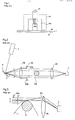
- FIG. 1 An apparatus utilizing electric vortex current as shown in Fig. 1 is already known for measuring the thickness of sheet-like products such as audio tapes, video tapes, etc., particularly the thickness of coatings of magnetic materials on the tape-like supports which are made of polyester or other plastics.
- reference numeral 1 designates a magnetic tape, in which tape-like support layer la made of transparent polyester or other plastics is provided with a coating layer lb of magnetic materials coated on a predetermined surface thereof, while 14 is a detector comprising an iron core 14a with one open end, which is wound by an exciting coil 14b connected with an oscillator 15.
- the oscillator 15 when the oscillator 15 is excited by the exciting coil 14b, a magnetic field due to the exciting coil 14b is generated at the open end of the iron core 14a.
- the exciting impedance fluctuates when a coating layer lb of magnetic material takes an adjacent position as shown. Since fluctuation of the exciting impedance depends upon characteristics, sizes (width, thickness), position, etc. of the magnetic material, the coating thickness of the magnetic material, i.e. the coating layer lb, can be measured by detecting the impedance fluctuation under predetermined conditions of the characteristics of the magnetic material, as well as the width and the position thereof.
- the conventional apparatus has a disadvantage in that it is in practice difficult to install in production lines.
- an optical micrometer is also known, wherein light beams such as laser beams are utilized with the body thereof positioned relatively far from the object whose thickness is to be measured.
- reference numeral 6 is a scanner such as polygonal mirror and a light beam from a light source 4 is scanned upward and downward onto a first lens 52, which irradiates a parallel beam onto a second lens 55, while the parallel beam reaches the second lens 55, through a gate 53 comprising an iris or restrictors 53a, 53b and collected by a receiving surface of a photoelectric converter 7. Therefore, when the light beam is scanned at a constant speed from the scanner 6 onto the first lens 52, the photoelectric converter 7 receives the light beam travelling up and down in the span of the gate 53.
- An object 54 to be measured is positioned between the first and second lenses 52, 55. Therefore, the photoelectric converter 7 does not receive any of the light beam whose path is covered by the vertical dimension of the object 54 tc be measured.
- the object 54 to be measured is substituted by a shaft, which supports a magnetic tape which partly surrounds it, so that a clearance between the upper iris or the restrictor 53a and the top surface of the magnetic tape 1 supported by the shaft 2 can be measured.
- a shaft which supports a magnetic tape which partly surrounds it
- a clearance between the upper iris or the restrictor 53a and the top surface of the magnetic tape 1 supported by the shaft 2 can be measured.
- the object to be measured the magnetic tape 1 in this case.
- the magnetic tape 1 is cylindrical and has a high surface reflectance and the light beam is projected upon a part (as identified by "d") near to the top cylinder-shaped part of the magnetic tape, the reflection 59 thereof is projected upon the light receiver 7.
- the light receiver 7 gives the detection result as if the magnetic tape 1 is not present. Moreover, the aforementioned influence of the reflected light beam depend upon the configuration of the object to be measured (the curvature difference of the magnetic tape 1 due to the diameter difference of the shaft 2), the surface reflectance thereof etc., resulting in difficult error compensation.
- the maim object of this invention is to provide a sheet thickness measuring apparatus which can continuously measure without contact and with high precision the thickness of a sheet-like product such as magnetic tape during the production process thereof.
- the invention provides a sheet thickness measuring apparatus comprising: a light beam source; a shaft for supporting a sheet which partly surrounds said shaft and whose thickness is to be measured; a light shading plate positioned in a plane including the central axis of said shaft and passing through the contact area between the surface of said shaft and the sheet to be measured, and which forms a slit of a predetermined width between the surface of said shaft and the edge thereof; a scanning apparatus including a scanner for scanning at a constant speed a light beam irradiated from said light beam source toward said slit in a plane which crosses the sheet to be measured supported by said shaft within said slit, and a photoelectric conversion device which receives the light beam through said slit, converts it into electric signals and outputs them; a timer for measuring the signal output duration of said photoelectric conversion device; and an arithmetic means which detects the clearance between the surface of the sheet supported by said shaft and the edge of said light shading plate on the basis of a measuring result by said timer and the scanning
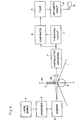
- Figure 4 shows the block diagram for the first embodiment of this invention, wherein reference numeral 1 is a sheet such as magnetic tape, whose thickness is to be measured. This sheet 1 is kept under tension with an appropriate force which tends to push the sheet 1 upward from the shaft 2.
- a light shading plate 3 is positioned on a plane (identified by reference numeral 20 in Fig. 4) which includes the central axis of the shaft 2 and passes through the contact area of the shaft 2 with the sheet 1.
- the edge of the light shading plate 3 facing the shaft 2 is positioned at a predetermined distance in parallel with the surface of the shaft 2, with the result that a slit 30 of predetermined width C is formed between them.
- a laser beam irradiated from the laser source 4 is condensed by the condenser 5 and transmitted as a light beam to the scanner 6, which scans the laser beam so that it traverses across the aforementioned slit 30 from the light shading plate 3 to the shaft 2 (or vice versa), by revolving a single plane or polygonal mirror.
- the photoelectric converter 7 for converting the received laser beam into an electric signal output is positioned facing the scanner 6 through the slit 30.
- the output signal of the photoelectric converter 7 is transmitted to the comparator 8 and the threshold circuit 11, which calculates the maximum output (available when the laser beam from the scanner 6 passes perfectly through the slit 30 and is then received by the photoelectric converter 7) and the minimum value (available when no laser beam from the scanner 6 is received by the photoelectric converter 7) therefrom and transmits the average value as a threshold value to the comparator 8.
- the comparator 8 converts the output signal of the photoelectric converter 7 into a rectangular waveform, which is outputted to a timer 9.
- the timer 9 counts the pulse width of the rectangular waveform outputted from the comparator 8 and acts as a timer which measures the outputting duration of the rectangular waveform, in other words, the receiving time duration of laser beam by the photoelectric converter 7.
- the output of the timer 9 is transmitted to the arithemetic circuit 10, which converts the output of the converter 9 according to a predetermined mathematical relationship or a conversion table.
- the thickness of the sheet 1 as the result of subtracting the converted value by the arithmetic circuit 10 from the width C is displayed at a display unit 12.
- the sheet 1 is moved at a predetermined constant speed while the shaft 2 is driven at the synchronized speed.
- the laser beam irradiated from the laser source 4 is condensed and focused at the slit 30 and scanned by the scanner 6 so that the laser traverses across the slit 30 from the light shading plate 3 to the shaft 2. Therefore, the photoelectric converter 7 receives the laser beam only when the laser beam from the scanner 6 is scanning within the slit 30.
- the scanning time duration can be detected from the length of time output signals from the timer 9 are present while the scanning speed of the laser beam and the distance between the scanner 6 and the photoelectric converter 7 are predetermined, and the counting result corresponding to the width C of the slit 30 is outputted to the arithmetic circuit 10 from the timer 9.
- the time counting value transmitted to the arithmetic circuit 10 corresponds to the value B (see Fig. 5) equal to the width C of the slit 30 subtracted by the thickness of the sheet 1, which is converted by the arithmetic circuit 10 and subtracted from the width C of the slit 30 so that the thickness of the sheet 1 is finally obtained.
- the thickness of the sheet 1 is displayed by the display unit 12.
- the coating thickness of magnetic material coated on the magnetic tape should be measured, it is enough to simply subtract the thickness of the support material of the magnetic tape 1 from the value determined and displayed by the arithmetic circuit 10 and display unit 12.
- any measuring error due to eccentricity of the shaft 2 can be avoided by using a measuring method shown in Figure 5, wherein two laser beams are scanned separately a part 2 with the sheet 1 being present and another part O1 with the sheet 1 being absent, in order to determine the difference and consequently obtain the thickness of the sheet 1. Therefore, the apparatus is so constructed that the laser beam is divided by a diffraction grating or a prism at an arbitrary position up to the scanner 6 and projected onto the same scanner 6.
- the system parts following the photoelectric converter 7 are positioned in two circuits and the output signals of two timers 9a, 9b, are processed by the arithmetic circuit 10.
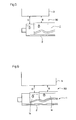
- FIG. 7 A second embodiment of this invention will now be described with reference to the block diagram in Fig. 7 and the schematic drawing in Fig. 8.
- the reference numerals 1, 2, 3, 4, 5, 6, 10, 12 and 30 designate the same parts as shown in Fig. 4, while the reference numerals 7a, 7b; 8a, 8b; 9a, 9b and lla, llb in Figs. 6 and 7 correspond to the reference numerals 7, 8, 9 and 11 of the first embodiment shown in Fig. 4.
- the light shading plate 3 is provided with the slit (hereinafter called a reference slit) of a predetermined width A, which extends parallel with the surface (centreline) of the shaft 2.
- a reference slit the slit
- the distance between the light shading plate 3 and the shaft 2, i.e. the width of the slit 30, is defined as C.
- the laser beams through the reference slit 31 and the slit 30 are received by the photoelectric converter 7a and 7b respectively.
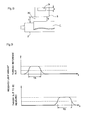
- Fig 9 is a graph showing the received light amounts of the both photoelectric converters 7a and 7b.
- the received light amount of the photoelectric converter 7a increases from the initial zero value, retains the maximum value during the time duration when the whole laser beam is passing through, then decreases slowly when the laser beam comes to the lower edge of the reference slit 31 (or the top part of the sheet 1) and finally becomes zero when the laser beam is entirely out of the reference slit 31 (or the slit 30).
- TA and TB in Fig. 9 show the times measured by the timers 9a and 9b with respect to the threshold value as reference determined by the threshold circuits lla and llb respectively.
- the width C of the slit 30 is known, so the thickness X of the sheet 1 is obtained from the following equation (4).
- the above calculation is processed by the arithmetic circuit 10 and the calculated thickness X of the sheet 1 is displayed on the display unit 12.
- the scanning apparatus consisting of the scanner 6 and the photoelectric converter 7 (7a, 7b) will be described next.
- Fig. 10 shows schematically the construction of the scanning apparatus of the sheet thickness measuring apparatus of the invention, wherein reference numeral 4 is the light source (or the condenser), 6 is the scanner (revolving mirror, etc.) 52 is a first lens, 54 is an object to be measured, 55 is a second lens, 7 is the light receiving device (or the photoelectric converter) and 70 is the light receiving slit provided at the light receiving surface of the photoelectric converter 7 and designed as a narrow rectangular form perpendicular to the traversing direction of the laser beam.
- the light , receiving surface of the photoelectric converter 7 receives only the laser beam passing through the light receiving slit 70.
- f l and f 2 are the focal distances of the first and second lenses 52 and 55 respectively.
- the centre of the scanner 6 is positioned at the front focal point of the first lens 52 and the object 54 to be measured (strictly speaking the point thereof to be measured) is positioned at the back focal point of the first lens 52 and the front focal point of the second lens 55, while the light receiving slit 70 is positioned at the back focal point of the second lens 55.
- the parallel laser beam from the laser source 4 is angularly scanned by the scanner 6 and projected onto the first lens 52.
- the reflection surface centre of the scanner 6 being positioned at the front focal point of the first lens 52, the scanned light beam as condensed through the first lens 52 is scanned in parallel with the light axis thereof.
- the received light amount rapidly changes by traversing across the object 54 to be measured, resulting in the improved detecting precision because the object 54 to be measured is positioned at the back focal point of the first lens 52 and the beam diameter is condensed to a minimum.
- the light beam is projected onto the second lens 55 after scanning the object 54 to be measured.
- the front focal point of the second lens 55 is positioned at the back focal point of the first lens 52 and the light beam passed through the second lens 55 becomes again a parallel beam.
- the light receiving slit 70 is positioned at the back focal point of the second lens 55, so that the parallel beam passes through with restriction of the width in the axial direction parallel to the traversing direction thereof and is then received by the photoelectric converter 7.
- this light receiving slit 70 will be described with reference to Fig. 11, wherein the left side shows the position of the object 54 to be measured.
- the light beam scanning the object 54 to be measured is reflected from the surface at the end part thereof, producing the beam component with an angle 6 larger than the original divergence angle of the beam.
- the light beam reflected from the top and bottom part of the object 54 to be measured follow the beam trajectories 60 and 61 respectively.
- These beams 60 and 61 are collimated to be in parallel with the centre light 62 through the second lens 55, but take positions deviated upward and downward from the light axis at the back focal point of the second lens 55.
- the light receiving slit 70 is provided at the back focal point of the second lens 55 so as to make only the light in the range of a minute width "a" near to the light axis pass through, the light reflected from the object surface is interrupted almost perfectly and is unable to reach the light receiving surface of the photoelectric converter 7. As this phenomenon takes place at any position when the object is perpendicular to the light axis, the reflected light in the whole scanning range is interrupted by the light receiving slit 70. Therefore almost all reflected light harmful to the detection of peripheries of the object to be measured is removed in this scanning apparatus and only the necessary centre light is received by the light receiving surface of the photoelectric converter 7, resulting in exact measurement.
- the thickness of any sheet-like product can be measured with high precision with a non-contact process. It is also possible to measure the thickness of magnetic material coated on magnetic tapes, continuously in the production lines thereof.
Landscapes
- Physics & Mathematics (AREA)
- General Physics & Mathematics (AREA)
- Length Measuring Devices By Optical Means (AREA)
Abstract
Description
- This invention relates to an apparatus suitable for measuring the thickness of sheet-like products such as magnetic tapes, particularly the thickness of coatings on sheet-like products.
- An apparatus utilizing electric vortex current as shown in Fig. 1 is already known for measuring the thickness of sheet-like products such as audio tapes, video tapes, etc., particularly the thickness of coatings of magnetic materials on the tape-like supports which are made of polyester or other plastics.
- In Fig. 1 reference numeral 1 designates a magnetic tape, in which tape-like support layer la made of transparent polyester or other plastics is provided with a coating layer lb of magnetic materials coated on a predetermined surface thereof, while 14 is a detector comprising an iron core 14a with one open end, which is wound by an
exciting coil 14b connected with anoscillator 15. - The functions of the apparatus will now be described. Referring to Fig. 1, when the
oscillator 15 is excited by theexciting coil 14b, a magnetic field due to theexciting coil 14b is generated at the open end of the iron core 14a. The exciting impedance fluctuates when a coating layer lb of magnetic material takes an adjacent position as shown. Since fluctuation of the exciting impedance depends upon characteristics, sizes (width, thickness), position, etc. of the magnetic material, the coating thickness of the magnetic material, i.e. the coating layer lb, can be measured by detecting the impedance fluctuation under predetermined conditions of the characteristics of the magnetic material, as well as the width and the position thereof. - It is difficult for the conventional apparatus with the construction mentioned above to measure reliably the thickness of the coating layer if the distance between the coating layer and the detector cannot be kept constant and narrow. Therefore, the conventional apparatus has a disadvantage in that it is in practice difficult to install in production lines.
- On the other hand, an optical micrometer is also known, wherein light beams such as laser beams are utilized with the body thereof positioned relatively far from the object whose thickness is to be measured.
- By using such apparatus, it is possible to measure the thickness after coating the magnetic material and then determine the coating thickness, if the tape-like support layer thereof is controlled at a constant thickness.
- Examples of such measuring apparatus are disclosed in U.S. Patent No. 4,082,463 as well as Japanese Patent Laid Open 57-161,608 (1982) and 57-104,807 (1982), wherein the construction shown in Fig. 2 is adopted.
- Referring to Fig. 2,
reference numeral 6 is a scanner such as polygonal mirror and a light beam from alight source 4 is scanned upward and downward onto afirst lens 52, which irradiates a parallel beam onto asecond lens 55, while the parallel beam reaches thesecond lens 55, through agate 53 comprising an iris orrestrictors photoelectric converter 7. Therefore, when the light beam is scanned at a constant speed from thescanner 6 onto thefirst lens 52, thephotoelectric converter 7 receives the light beam travelling up and down in the span of thegate 53. - An
object 54 to be measured is positioned between the first andsecond lenses photoelectric converter 7 does not receive any of the light beam whose path is covered by the vertical dimension of theobject 54 tc be measured. The vertical direction (a distance between the iris or therestrictor 53a and anotherrestrictor 53b) thereof being known, it is possible to measure the vertical (in Fig. 2) dimension of theobject 54 if the time interval from initial incidence of the light beam onto thephotoelectric converter 7 to the interruption thereof, the length of time of interruption and the time interval from reincidence of the light beam to the reinterruption thereof can be detected. - In such apparatus, as shown in Fig. 3, the
object 54 to be measured is substituted by a shaft, which supports a magnetic tape which partly surrounds it, so that a clearance between the upper iris or therestrictor 53a and the top surface of the magnetic tape 1 supported by theshaft 2 can be measured. However, such an apparatus has the following disadvantage for some configurations and reflectances of the object to be measured (the magnetic tape 1 in this case). For instance, if the magnetic tape 1 (the object to be measured) is cylindrical and has a high surface reflectance and the light beam is projected upon a part (as identified by "d") near to the top cylinder-shaped part of the magnetic tape, thereflection 59 thereof is projected upon thelight receiver 7. - Therefore, in spite of the actual presence of the magnetic tape 1 as the object to be measured, the
light receiver 7 gives the detection result as if the magnetic tape 1 is not present. Moreover, the aforementioned influence of the reflected light beam depend upon the configuration of the object to be measured (the curvature difference of the magnetic tape 1 due to the diameter difference of the shaft 2), the surface reflectance thereof etc., resulting in difficult error compensation. - This invention aimed to solve the aforementioned difficulties. The maim object of this invention is to provide a sheet thickness measuring apparatus which can continuously measure without contact and with high precision the thickness of a sheet-like product such as magnetic tape during the production process thereof.
- Accordingly the invention provides a sheet thickness measuring apparatus comprising: a light beam source; a shaft for supporting a sheet which partly surrounds said shaft and whose thickness is to be measured; a light shading plate positioned in a plane including the central axis of said shaft and passing through the contact area between the surface of said shaft and the sheet to be measured, and which forms a slit of a predetermined width between the surface of said shaft and the edge thereof; a scanning apparatus including a scanner for scanning at a constant speed a light beam irradiated from said light beam source toward said slit in a plane which crosses the sheet to be measured supported by said shaft within said slit, and a photoelectric conversion device which receives the light beam through said slit, converts it into electric signals and outputs them; a timer for measuring the signal output duration of said photoelectric conversion device; and an arithmetic means which detects the clearance between the surface of the sheet supported by said shaft and the edge of said light shading plate on the basis of a measuring result by said timer and the scanning speed of the light beam by said scanning apparatus and determines the sheet thickness by subtracting the detected result from said slit width.
- The above and further objects and features of the invention will more fully be apparent from the following detailed description with accompanying drawings.
- Figure 1 shows schematically a conventional, electric vortex current type sheet thickness measuring apparatus which is used to measure the thickness of magnetic material coated on a magnetic tape;
- Figure 2 shows schematically a conventional optical micrometer applicable also as a sheet thickness measuring apparatus;
- Figure 3 is an operational illustration thereof;
- Figure 4 is a block diagram showing first embodiment of the sheet thickness measuring apparatus of the invention;
- Figures 5, 6 are operational illustrations thereof;
- Figure 7 is a block diagram showing second embodiment of the sheet thickness measuring apparatus of the invention,
- Figure 8 is an operational illustration thereof;
- Figure 9 is a diagram showing the received light amount of the photoelectric converter;
- Figure 10 shows schematically a construction of the scanning apparatus of the invention; and
- Figure 11 is an operational illustration thereof.
- The sheet thickness measuring apparatus of the invention will be described in detail with reference to the drawings attached.
- Figure 4 shows the block diagram for the first embodiment of this invention, wherein reference numeral 1 is a sheet such as magnetic tape, whose thickness is to be measured. This sheet 1 is kept under tension with an appropriate force which tends to push the sheet 1 upward from the
shaft 2. Alight shading plate 3 is positioned on a plane (identified byreference numeral 20 in Fig. 4) which includes the central axis of theshaft 2 and passes through the contact area of theshaft 2 with the sheet 1. The edge of thelight shading plate 3 facing theshaft 2 is positioned at a predetermined distance in parallel with the surface of theshaft 2, with the result that aslit 30 of predetermined width C is formed between them. - A laser beam irradiated from the
laser source 4 is condensed by thecondenser 5 and transmitted as a light beam to thescanner 6, which scans the laser beam so that it traverses across theaforementioned slit 30 from thelight shading plate 3 to the shaft 2 (or vice versa), by revolving a single plane or polygonal mirror. - The
photoelectric converter 7 for converting the received laser beam into an electric signal output is positioned facing thescanner 6 through theslit 30. The output signal of thephotoelectric converter 7 is transmitted to thecomparator 8 and the threshold circuit 11, which calculates the maximum output (available when the laser beam from thescanner 6 passes perfectly through theslit 30 and is then received by the photoelectric converter 7) and the minimum value (available when no laser beam from thescanner 6 is received by the photoelectric converter 7) therefrom and transmits the average value as a threshold value to thecomparator 8. - According to the aforementioned threshold value from the threshold circuit 11, the
comparator 8 converts the output signal of thephotoelectric converter 7 into a rectangular waveform, which is outputted to atimer 9. - The
timer 9 counts the pulse width of the rectangular waveform outputted from thecomparator 8 and acts as a timer which measures the outputting duration of the rectangular waveform, in other words, the receiving time duration of laser beam by thephotoelectric converter 7. The output of thetimer 9 is transmitted to thearithemetic circuit 10, which converts the output of theconverter 9 according to a predetermined mathematical relationship or a conversion table. The thickness of the sheet 1 as the result of subtracting the converted value by thearithmetic circuit 10 from the width C is displayed at adisplay unit 12. The sheet 1 is moved at a predetermined constant speed while theshaft 2 is driven at the synchronized speed. - Now the functions of the apparatus of the invention abovementioned will be described. The laser beam irradiated from the
laser source 4 is condensed and focused at theslit 30 and scanned by thescanner 6 so that the laser traverses across theslit 30 from thelight shading plate 3 to theshaft 2. Therefore, thephotoelectric converter 7 receives the laser beam only when the laser beam from thescanner 6 is scanning within theslit 30. The scanning time duration can be detected from the length of time output signals from thetimer 9 are present while the scanning speed of the laser beam and the distance between thescanner 6 and thephotoelectric converter 7 are predetermined, and the counting result corresponding to the width C of theslit 30 is outputted to thearithmetic circuit 10 from thetimer 9. - However, the sheet 1 is actually positioned on the surface of the
shaft 2 within theslit 30, therefore, the time counting value transmitted to thearithmetic circuit 10 corresponds to the value B (see Fig. 5) equal to the width C of theslit 30 subtracted by the thickness of the sheet 1, which is converted by thearithmetic circuit 10 and subtracted from the width C of theslit 30 so that the thickness of the sheet 1 is finally obtained. The thickness of the sheet 1 is displayed by thedisplay unit 12. - If the coating thickness of magnetic material coated on the magnetic tape should be measured, it is enough to simply subtract the thickness of the support material of the magnetic tape 1 from the value determined and displayed by the
arithmetic circuit 10 anddisplay unit 12. - Any measuring error due to eccentricity of the
shaft 2 can be avoided by using a measuring method shown in Figure 5, wherein two laser beams are scanned separately apart ② with the sheet 1 being present and another part O1 with the sheet 1 being absent, in order to determine the difference and consequently obtain the thickness of the sheet 1. Therefore, the apparatus is so constructed that the laser beam is divided by a diffraction grating or a prism at an arbitrary position up to thescanner 6 and projected onto thesame scanner 6. As an alternative, the system parts following thephotoelectric converter 7 are positioned in two circuits and the output signals of twotimers arithmetic circuit 10. - When the surface of the sheet 1, whose thickness is to be measured, is not coated completely but only partly and the supported layer lb is exposed, two laser beams scan the clearance B of a
part ② of a coating layer la and the clearance D of a part (3) where the support layer lb is exposed respectively as shown in Fig. 6. Then a thickness of coating layer la of sheet 1 is measured directly by the same process as mentioned above. - A second embodiment of this invention will now be described with reference to the block diagram in Fig. 7 and the schematic drawing in Fig. 8. The
reference numerals reference numerals reference numerals - In this embodiment, the
light shading plate 3 is provided with the slit (hereinafter called a reference slit) of a predetermined width A, which extends parallel with the surface (centreline) of theshaft 2. Similarly to the embodiment of Fig. 4, there are two circuits consisting of thephotoelectric converters comparators timers timers arithmetic circuit 10. - The functions of the aforementioned second embodiment will now be described, wherein the distance between the
light shading plate 3 and theshaft 2, i.e. the width of theslit 30, is defined as C. In this second embodiment the laser beams through the reference slit 31 and theslit 30 are received by thephotoelectric converter photoelectric converters - When the laser beam begins to enter the reference slit 31 (or the slit 30) from the upper edge thereof, the received light amount of the
photoelectric converter 7a (or 7b) increases from the initial zero value, retains the maximum value during the time duration when the whole laser beam is passing through, then decreases slowly when the laser beam comes to the lower edge of the reference slit 31 (or the top part of the sheet 1) and finally becomes zero when the laser beam is entirely out of the reference slit 31 (or the slit 30). TA and TB in Fig. 9 show the times measured by thetimers - If it is supposed the traversing speed of the light beam on the
light shading plate 3 is V,

- Therefore, from the above equations (1) and (2),

- Moreover, the width C of the
slit 30 is known, so the thickness X of the sheet 1 is obtained from the following equation (4).
- The above calculation is processed by the
arithmetic circuit 10 and the calculated thickness X of the sheet 1 is displayed on thedisplay unit 12. - The scanning apparatus consisting of the
scanner 6 and the photoelectric converter 7 (7a, 7b) will be described next. - Fig. 10 shows schematically the construction of the scanning apparatus of the sheet thickness measuring apparatus of the invention, wherein
reference numeral 4 is the light source (or the condenser), 6 is the scanner (revolving mirror, etc.) 52 is a first lens, 54 is an object to be measured, 55 is a second lens, 7 is the light receiving device (or the photoelectric converter) and 70 is the light receiving slit provided at the light receiving surface of thephotoelectric converter 7 and designed as a narrow rectangular form perpendicular to the traversing direction of the laser beam. The light , receiving surface of thephotoelectric converter 7 receives only the laser beam passing through the light receiving slit 70. - In Fig. 10 fl and f2 are the focal distances of the first and
second lenses scanner 6 is positioned at the front focal point of thefirst lens 52 and theobject 54 to be measured (strictly speaking the point thereof to be measured) is positioned at the back focal point of thefirst lens 52 and the front focal point of thesecond lens 55, while the light receiving slit 70 is positioned at the back focal point of thesecond lens 55. - The operations of the apparatus will be described next. The parallel laser beam from the
laser source 4 is angularly scanned by thescanner 6 and projected onto thefirst lens 52. The reflection surface centre of thescanner 6 being positioned at the front focal point of thefirst lens 52, the scanned light beam as condensed through thefirst lens 52 is scanned in parallel with the light axis thereof. The received light amount rapidly changes by traversing across theobject 54 to be measured, resulting in the improved detecting precision because theobject 54 to be measured is positioned at the back focal point of thefirst lens 52 and the beam diameter is condensed to a minimum. - The light beam is projected onto the
second lens 55 after scanning theobject 54 to be measured. The front focal point of thesecond lens 55 is positioned at the back focal point of thefirst lens 52 and the light beam passed through thesecond lens 55 becomes again a parallel beam. The light receiving slit 70 is positioned at the back focal point of thesecond lens 55, so that the parallel beam passes through with restriction of the width in the axial direction parallel to the traversing direction thereof and is then received by thephotoelectric converter 7. - The function of this light receiving slit 70 will be described with reference to Fig. 11, wherein the left side shows the position of the
object 54 to be measured. As described previously, the light beam scanning theobject 54 to be measured is reflected from the surface at the end part thereof, producing the beam component with anangle 6 larger than the original divergence angle of the beam. The light beam reflected from the top and bottom part of theobject 54 to be measured follow thebeam trajectories beams second lens 55, but take positions deviated upward and downward from the light axis at the back focal point of thesecond lens 55. If the light receiving slit 70 is provided at the back focal point of thesecond lens 55 so as to make only the light in the range of a minute width "a" near to the light axis pass through, the light reflected from the object surface is interrupted almost perfectly and is unable to reach the light receiving surface of thephotoelectric converter 7. As this phenomenon takes place at any position when the object is perpendicular to the light axis, the reflected light in the whole scanning range is interrupted by the light receiving slit 70. Therefore almost all reflected light harmful to the detection of peripheries of the object to be measured is removed in this scanning apparatus and only the necessary centre light is received by the light receiving surface of thephotoelectric converter 7, resulting in exact measurement. - According to this invention as described above, the thickness of any sheet-like product can be measured with high precision with a non-contact process. It is also possible to measure the thickness of magnetic material coated on magnetic tapes, continuously in the production lines thereof.
Claims (11)
wherein said photoelectric conversion device (7) is provided with a light receiving slit (70) at the light receiving surface thereof with an appropriate width in the longitudinal direction crossing at right angles with the scanning direction of the light beam and said scanner (6) is positioned at the front focal point of said first lens (52), said slit (30) is positioned at the back focal point of said first lens (52) and at the front focal point of said second lens (55) and said light receiving slit (70) is positioned at the back focal point of said second lens (55) so that the light beam is projected through said light receiving slit (70) onto the photoelectric conversion device (7).
Applications Claiming Priority (6)
| Application Number | Priority Date | Filing Date | Title |
|---|---|---|---|
| JP17460985A JPS6234005A (en) | 1985-08-06 | 1985-08-06 | Film thickness measuring device |
| JP174609/85 | 1985-08-06 | ||
| JP176781/85 | 1985-08-09 | ||
| JP17678185A JPS6236507A (en) | 1985-08-09 | 1985-08-09 | Film thickness measuring device |
| JP209436/85 | 1985-09-20 | ||
| JP20943685A JPS6269108A (en) | 1985-09-20 | 1985-09-20 | Object edge detection device |
Publications (3)
| Publication Number | Publication Date |
|---|---|
| EP0211654A2 true EP0211654A2 (en) | 1987-02-25 |
| EP0211654A3 EP0211654A3 (en) | 1988-09-28 |
| EP0211654B1 EP0211654B1 (en) | 1991-06-05 |
Family
ID=27323973
Family Applications (1)
| Application Number | Title | Priority Date | Filing Date |
|---|---|---|---|
| EP86306054A Expired EP0211654B1 (en) | 1985-08-06 | 1986-08-06 | Sheet coating thickness measuring apparatus |
Country Status (3)
| Country | Link |
|---|---|
| US (1) | US4730116A (en) |
| EP (1) | EP0211654B1 (en) |
| DE (1) | DE3679610D1 (en) |
Cited By (6)
| Publication number | Priority date | Publication date | Assignee | Title |
|---|---|---|---|---|
| EP0243961A3 (en) * | 1986-04-29 | 1989-03-22 | Mitsubishi Denki Kabushiki Kaisha | Film thickness measuring device |
| US4922112A (en) * | 1987-08-28 | 1990-05-01 | Agfa-Gevaert Aktiengesellschaft | Apparatus for determining the thickness of layer supports |
| EP0304795A3 (en) * | 1987-08-28 | 1990-09-12 | Agfa-Gevaert Ag | Device for checking of coated and uncoated foils |
| FR2644238A1 (en) * | 1989-03-08 | 1990-09-14 | Westinghouse Electric Corp | APPARATUS AND METHOD FOR DETERMINING THE SIZES OF TUBES |
| EP0324896A3 (en) * | 1988-01-19 | 1990-10-10 | Mitsubishi Denki Kabushikikaisha | Thickness measuring method |
| US4966460A (en) * | 1987-10-28 | 1990-10-30 | The Ingersoll Milling Machine Company | Laser gauging of rotary cutting tools |
Families Citing this family (6)
| Publication number | Priority date | Publication date | Assignee | Title |
|---|---|---|---|---|
| JPS62255806A (en) * | 1986-04-29 | 1987-11-07 | Mitsubishi Electric Corp | Method and instrument for measuring film thickness |
| US4878754A (en) * | 1986-10-16 | 1989-11-07 | Tokyo Keiki Co. Ltd. | Method of and apparatus for measuring irregularities of road surface |
| JP3150404B2 (en) * | 1992-02-25 | 2001-03-26 | 株式会社トーメー | Method and apparatus for measuring refractive power in optical system |
| US6241244B1 (en) * | 1997-11-28 | 2001-06-05 | Diebold, Incorporated | Document sensor for currency recycling automated banking machine |
| DE10054227A1 (en) * | 2000-11-02 | 2002-08-01 | Musa Kazalan | Measuring device for monitoring the outer contour of profiles during production |
| JP7613857B2 (en) * | 2020-09-16 | 2025-01-15 | 浜松ホトニクス株式会社 | Photodetector and beat spectrometer |
Family Cites Families (13)
| Publication number | Priority date | Publication date | Assignee | Title |
|---|---|---|---|---|
| US2548755A (en) * | 1947-12-12 | 1951-04-10 | Standard Electronics Res Corp | Optical area measuring system |
| US3518441A (en) * | 1968-01-24 | 1970-06-30 | Neotec Corp | Optical gage for measuring the thickness of a continuous web |
| US3743428A (en) * | 1971-08-04 | 1973-07-03 | Du Pont | Device for optically measuring a dimension of an object |
| US3883249A (en) * | 1972-05-15 | 1975-05-13 | Timothy R Pryor | Z-factor and other diffractographic displacement and profile sensors |
| US4168911A (en) * | 1975-05-07 | 1979-09-25 | Diffracto, Ltd. | Diffractographic and other sensors utilizing diffraction waves |
| US4182259A (en) * | 1978-10-04 | 1980-01-08 | The Dow Chemical Company | Apparatus for measuring coating thickness on an applicator roll |
| DE2906494C2 (en) * | 1979-02-20 | 1981-02-12 | Siemens Ag, 1000 Berlin Und 8000 Muenchen | Method and device for contactless distance or thickness measurement with regulation of the direction of the light beam |
| JPS5644803A (en) * | 1979-09-21 | 1981-04-24 | Bridgestone Corp | System measuring for thickness of nonmetallic sheet like object |
| GB2061495B (en) * | 1979-10-17 | 1984-03-14 | Atomic Energy Authority Uk | Measurement of the thickness of a liquid films |
| CH645462A5 (en) * | 1980-03-25 | 1984-09-28 | Zumbach Electronic Ag | METHOD AND DEVICE FOR THE CONTACTLESS MEASUREMENT OF A DIMENSION OF AT LEAST ONE OBJECT. |
| JPS57104807A (en) * | 1980-12-20 | 1982-06-30 | Anritsu Corp | Edge detector for object |
| JPS57161608A (en) * | 1981-03-31 | 1982-10-05 | Anritsu Corp | Measuring device for object size |
| US4532723A (en) * | 1982-03-25 | 1985-08-06 | General Electric Company | Optical inspection system |
-
1986
- 1986-07-18 US US06/886,782 patent/US4730116A/en not_active Expired - Fee Related
- 1986-08-06 DE DE8686306054T patent/DE3679610D1/en not_active Expired - Lifetime
- 1986-08-06 EP EP86306054A patent/EP0211654B1/en not_active Expired
Cited By (9)
| Publication number | Priority date | Publication date | Assignee | Title |
|---|---|---|---|---|
| EP0243961A3 (en) * | 1986-04-29 | 1989-03-22 | Mitsubishi Denki Kabushiki Kaisha | Film thickness measuring device |
| US4922112A (en) * | 1987-08-28 | 1990-05-01 | Agfa-Gevaert Aktiengesellschaft | Apparatus for determining the thickness of layer supports |
| EP0304795A3 (en) * | 1987-08-28 | 1990-09-12 | Agfa-Gevaert Ag | Device for checking of coated and uncoated foils |
| EP0304793A3 (en) * | 1987-08-28 | 1990-09-12 | Agfa-Gevaert Ag | Device for the determination of the thickness of film bases |
| US4966460A (en) * | 1987-10-28 | 1990-10-30 | The Ingersoll Milling Machine Company | Laser gauging of rotary cutting tools |
| EP0324896A3 (en) * | 1988-01-19 | 1990-10-10 | Mitsubishi Denki Kabushikikaisha | Thickness measuring method |
| FR2644238A1 (en) * | 1989-03-08 | 1990-09-14 | Westinghouse Electric Corp | APPARATUS AND METHOD FOR DETERMINING THE SIZES OF TUBES |
| GB2231147A (en) * | 1989-03-08 | 1990-11-07 | Westinghouse Electric Corp | Determination of dimensions of tubes |
| GB2231147B (en) * | 1989-03-08 | 1993-11-03 | Westinghouse Electric Corp | Determination of dimensions of tubes |
Also Published As
| Publication number | Publication date |
|---|---|
| DE3679610D1 (en) | 1991-07-11 |
| EP0211654B1 (en) | 1991-06-05 |
| US4730116A (en) | 1988-03-08 |
| EP0211654A3 (en) | 1988-09-28 |
Similar Documents
| Publication | Publication Date | Title |
|---|---|---|
| EP0211654B1 (en) | Sheet coating thickness measuring apparatus | |
| EP0279347B1 (en) | Optical axis displacement sensor | |
| KR920003534B1 (en) | Optical apparatus for the detection of holes | |
| JPH01143945A (en) | Detecting method for defect in tape | |
| US4097160A (en) | Method for inspecting object defection by light beam | |
| US20070052978A1 (en) | Device and method for measuring the thickness of a transparent sample | |
| US4284357A (en) | Device for continuously inspecting a surface | |
| JPH06102028A (en) | Optical non-contact distance measuring machine and measuring method | |
| RU2035721C1 (en) | Method of checking transparency of flat light-translucent materials | |
| JPS6269113A (en) | Inspection instrument for surface of screw | |
| JPS59226802A (en) | Edge detector of optical measuring equipment | |
| JPS6365885B2 (en) | ||
| JPS6234005A (en) | Film thickness measuring device | |
| JPS58100742A (en) | Detecting method for abrasion of glass bottle | |
| JPS62269007A (en) | Optical displacement measuring apparatus | |
| JPS6069503A (en) | Measuring method of shape of steel plate end part | |
| JPH07174513A (en) | Periodic-pattern measuring apparatus | |
| SU1675664A1 (en) | Method of inspection of geometrical parameters of rings | |
| JPS6021439A (en) | Surface-defect detecting device | |
| JPH04240507A (en) | Measuring method of minute dimension | |
| JPH01291103A (en) | Width measuring instrument | |
| JPH0569165B2 (en) | ||
| JPH1194524A (en) | Method for measuring height of trolley line | |
| JPH0296603A (en) | Gap measuring device | |
| JP2002005636A (en) | Shape measuring device |
Legal Events
| Date | Code | Title | Description |
|---|---|---|---|
| PUAI | Public reference made under article 153(3) epc to a published international application that has entered the european phase |
Free format text: ORIGINAL CODE: 0009012 |
|
| AK | Designated contracting states |
Kind code of ref document: A2 Designated state(s): DE FR GB SE |
|
| PUAL | Search report despatched |
Free format text: ORIGINAL CODE: 0009013 |
|
| AK | Designated contracting states |
Kind code of ref document: A3 Designated state(s): DE FR GB SE |
|
| 17P | Request for examination filed |
Effective date: 19881006 |
|
| 17Q | First examination report despatched |
Effective date: 19891109 |
|
| GRAA | (expected) grant |
Free format text: ORIGINAL CODE: 0009210 |
|
| AK | Designated contracting states |
Kind code of ref document: B1 Designated state(s): DE FR GB SE |
|
| REF | Corresponds to: |
Ref document number: 3679610 Country of ref document: DE Date of ref document: 19910711 |
|
| ET | Fr: translation filed | ||
| PLBE | No opposition filed within time limit |
Free format text: ORIGINAL CODE: 0009261 |
|
| STAA | Information on the status of an ep patent application or granted ep patent |
Free format text: STATUS: NO OPPOSITION FILED WITHIN TIME LIMIT |
|
| 26N | No opposition filed | ||
| EAL | Se: european patent in force in sweden |
Ref document number: 86306054.7 |
|
| PGFP | Annual fee paid to national office [announced via postgrant information from national office to epo] |
Ref country code: GB Payment date: 19950726 Year of fee payment: 10 |
|
| PGFP | Annual fee paid to national office [announced via postgrant information from national office to epo] |
Ref country code: FR Payment date: 19950809 Year of fee payment: 10 Ref country code: DE Payment date: 19950809 Year of fee payment: 10 |
|
| PGFP | Annual fee paid to national office [announced via postgrant information from national office to epo] |
Ref country code: SE Payment date: 19950816 Year of fee payment: 10 |
|
| REG | Reference to a national code |
Ref country code: GB Ref legal event code: 746 Effective date: 19950809 |
|
| REG | Reference to a national code |
Ref country code: FR Ref legal event code: D6 |
|
| PG25 | Lapsed in a contracting state [announced via postgrant information from national office to epo] |
Ref country code: GB Effective date: 19960806 |
|
| PG25 | Lapsed in a contracting state [announced via postgrant information from national office to epo] |
Ref country code: SE Effective date: 19960807 |
|
| GBPC | Gb: european patent ceased through non-payment of renewal fee |
Effective date: 19960806 |
|
| PG25 | Lapsed in a contracting state [announced via postgrant information from national office to epo] |
Ref country code: FR Effective date: 19970430 |
|
| PG25 | Lapsed in a contracting state [announced via postgrant information from national office to epo] |
Ref country code: DE Effective date: 19970501 |
|
| EUG | Se: european patent has lapsed |
Ref document number: 86306054.7 |
|
| REG | Reference to a national code |
Ref country code: FR Ref legal event code: ST |