EP0211276A2 - Soil-tilling implement - Google Patents
Soil-tilling implement Download PDFInfo
- Publication number
- EP0211276A2 EP0211276A2 EP86109591A EP86109591A EP0211276A2 EP 0211276 A2 EP0211276 A2 EP 0211276A2 EP 86109591 A EP86109591 A EP 86109591A EP 86109591 A EP86109591 A EP 86109591A EP 0211276 A2 EP0211276 A2 EP 0211276A2
- Authority
- EP
- European Patent Office
- Prior art keywords
- tool
- receiving opening
- machine according
- soil cultivation
- cultivation machine
- Prior art date
- Legal status (The legal status is an assumption and is not a legal conclusion. Google has not performed a legal analysis and makes no representation as to the accuracy of the status listed.)
- Granted
Links
Images


Classifications
-
- A—HUMAN NECESSITIES
- A01—AGRICULTURE; FORESTRY; ANIMAL HUSBANDRY; HUNTING; TRAPPING; FISHING
- A01B—SOIL WORKING IN AGRICULTURE OR FORESTRY; PARTS, DETAILS, OR ACCESSORIES OF AGRICULTURAL MACHINES OR IMPLEMENTS, IN GENERAL
- A01B33/00—Tilling implements with rotary driven tools, e.g. in combination with fertiliser distributors or seeders, with grubbing chains, with sloping axles, with driven discs
- A01B33/08—Tools; Details, e.g. adaptations of transmissions or gearings
- A01B33/14—Attaching the tools to the rotating shaft, e.g. resiliently or flexibly-attached tools
- A01B33/146—Attaching the tools to the rotating shaft, e.g. resiliently or flexibly-attached tools the rotating shaft being oriented vertically or steeply inclined
Definitions
- the invention relates to a tillage machine according to the preamble of claim 1.
- a tillage machine is known from DE-GM 82 13 540.
- the tools in this tillage machine are each fastened to the tool rotor with the aid of two screw bolts.
- the disadvantage of this type of fastening is that on the one hand relatively large and high-strength bolts must be used.
- the bolts must be tightened with very large forces so that the tools remain securely attached to the tool gyro even under the most difficult operating conditions. It is very complex and time-consuming when the tools have to be replaced.
- Replacing the tools in the known machine takes a very long time, especially to loosen the screws and tighten them again. Furthermore, it is practically impossible, especially on the field or for the farmer alone with the help of on-board tools, to replace tines on the field.
- the invention has for its object to significantly simplify and facilitate the replacement of tools, so that the tools can be replaced in a very short time.
- the AMAZONE rotary cultivator brochure with the print reference "D 574 * 2.84" already discloses a fastening for straight tines which are inserted into a receiving opening pointing downwards, so that there is a positive connection between the tools and the receiving openings of the tool rotors.
- the tools are held in the receiving openings by a safety bolt.
- webs directed downward to form the receiving openings are located on the underside of the tool gyroscope and that a plate connecting at least two webs is welded onto the underside of the webs.
- the invention provides that a countersink is arranged on the top of the tool gyroscope in the region of the bores in which the bolts are arranged. It is provided according to the invention that the bolts are sunk on the top of the tool gyroscope. This means that stones cannot get caught between the bolts and the gearbox housing and therefore cannot damage the gearbox housing.
- the countersink is designed as a hexagon. This means that hexagon screws can also be arranged in the recess. This is particularly advantageous if the bolts are to be secured with a screw nut. The bolts cannot therefore twist.
- the recess formed as a hexagon or other forms of recess also has the advantage that the bolts cannot rotate. This prevents wear.
- the invention provides that the securing parts or quick-release fasteners of the bolts are arranged in a protected manner on the underside of the tool gyroscope. This avoids damage to the safety parts during rough use of the machine.
- a protective screen preferably standing, is arranged on the underside of the tool gyroscope, at least in the direction of rotation of the tool gyroscope, in front of the bolts.
- the tool rotors having a round cross section that the diameter of the tool rotors corresponds approximately to the distance between the upper outer parts of the tools.
- a particularly good protected arrangement of the fastening part of the tools is achieved in that the tool rotors have a narrow circumferential ring which at least partially covers the fastening part of the tool.
- the receiving opening at least in its outer radial area from the center of the receiving opening in the tangential direction, has a substantially greater height than the height of the fastening parts of the tools .
- the fastening part can rotate by a certain amount over a certain range of its length within the receiving opening about an axis lying perpendicular to the axis of rotation of the tool gyroscope.
- the tillage tool hits stones that are in the ground or are stuck, so that the tillage tool can move backwards by a certain amount by the fastening part being able to twist inside the receiving opening like a torsion spring.
- integrally formed fastening part is connected to the processing part of the tillage tool results in a surprisingly simple manner in a very effective and simple suspension option for the tillage tool, when it encounters stones or other obstacles located in the ground.
- the tillage tool itself is designed as a spring element and the larger receiving opening located in the outer radial area of the receiving opening achieves an extremely effective suspension for the tool rotors that is insensitive to external influences.
- the invention provides that the receiving openings in the tool rotors for the fastening parts extend at least approximately to the center of the tool rotator and that the fastening parts extend at least approximately to Extend the center of the tool top into the receiving openings.
- a sufficiently secure attachment of the tillage tool to the tool gyroscope is achieved, since the attachment part is held in its receptacle opening at its outer end over a sufficiently long path.
- the receiving opening then has approximately a cross section which corresponds to the cross section of the fastening part.
- the receiving opening in its area closest to the center of the tool gyroscope has a cross-section which corresponds at least approximately to the cross-section of the fastening parts of the tools, and that the receiving openings are above all at a distance from the center of the tool gyroscope in the tangential direction increase gradually or at least approximately continuously in the lateral areas of the receiving openings.
- the upper and lower surfaces of the receiving openings run obliquely upwards or downwards from the center of the receiving opening. This results in a very simple design of the receiving openings, which is mirror-symmetrical to the central longitudinal axis, so that the tool gyroscope with the receiving opening can be produced in a simple manner as a forged part. It is then provided that the receiving opening is closed and formed by a base plate welded to the tool gyroscope.
- the receiving opening has an approximately X-shaped cross section, this cross section extending from the outside inwards in the radial direction and at a distance from the axis of rotation of the tool gyroscope into one cross-section at least approximately corresponds to the cross-section of the inner part of the fastening part of the tool.
- a further improvement is achieved in a manner according to the invention in that in the middle of the receiving opening there is a web extending in the radial direction on the lower and the upper side of the receiving opening, the vertical distance between the upper and the lower web being reduced corresponds approximately to the height of the fastening part.
- the invention provides that: - the fastening part on its side facing away from the tool has a recess which corresponds to the contour of the hub of the tool gyroscope, that the receiving opening extends to the center of the tool gyroscope to the side of the hub of the tool gyroscope, and that the tongues of the fastening part formed by the recess are laterally the Extend the hub to approximately the center of the tool top.
- the invention provides, in order to achieve a secure mounting or holding possibility for the fastening part while at the same time having a sufficiently long twisting path of the fastening part of the tillage tool, that the larger cross-section of the receiving opening does not exceed at least half the length of the receiving opening of the fastening part Fifth of the length of the receiving opening or the fastening part extends.
- German patent 28 49 869 already discloses a tillage machine with a plurality of tool rotors which are arranged next to one another in a row running transversely to the direction of travel and have downward-facing tillage tools. These tillage tools are fastened to a spring package lying horizontally and extending transversely to the axis of rotation of the tool gyroscope, so that these tillage tools when they strike the ground Know any stones or other obstacles to move backwards by turning the spring assembly to which the tools are attached.
- This arrangement of the tillage tools on flat spring assemblies is structurally very complex and expensive. Furthermore, the tillage tools can only be replaced in a time-consuming and complex manner if the tillage tools are worn out.
- the invention provides, so that no damage to the tines or the machine occurs even under the most extreme conditions, that the receiving opening for the fastening part of the tool extends at least approximately over the entire diameter of the tool gyroscope, and that the receiving opening extends from the beginning of the fastening part in the direction of the side facing the tool expands continuously on its upper and lower side at least in the lateral areas of the receiving opening.
- This creates an extremely long fastening part which extends practically over the entire width or diameter of the tool gyroscope and which can rotate in the receiving opening practically over the entire length of the receiving opening. This results in a very large alternative for the tillage part of the tillage tine when it hits a stone stuck in the ground.
- the invention provides that the receiving opening extends over at least two thirds of its length X-shaped cross section.
- each tool gyroscope has two receiving openings which are arranged one below the other. In another embodiment, it is provided according to the invention that each tool gyroscope has two receiving openings which are arranged side by side. This creates an extremely compact and flat tool rotor.
- the tillage machine can either be designed as a rotary cultivator or as a rotary harrow.
- the main difference between a rotary cultivator and a rotary harrow is the arrangement of the tools.
- this machine is referred to as a rotary cultivator, but when the tool tips continue to run when viewed in the direction of rotation; i.e. are arranged sluggishly, one speaks of a rotary harrow.
- the tillage machine has the frame 1, in which the tool rotors 2 are arranged next to one another in a row running transversely to the direction of travel.
- the tool rotors 2 are driven by the power take-off of the tractor moving the tillage machine, the respectively adjacent tool rotors 2 rotating in the opposite direction of rotation indicated by the arrow 3 about upright axes.
- the tool rotors 2 are plate-shaped.
- the tools 4 projecting downward are attached to these tool rotors 2.
- the packer roller 6 with its tines 7 arranged on the circumference is arranged behind the tillage machine.
- the tool rotors 2 have receiving openings 8 pointing radially outwards for the respective fastening part 9 of the tools 4.
- the tools 4 each have a processing part 10 which processes and a the soil fastening part 9 angled approximately at right angles to the machining part 10. This fastening part 9 has the two bores 11.
- the tool gyroscope 2 consists of the upper forged part 12, which has a central bore for attachment to a drive shaft of a transmission, not shown, which is arranged in the frame 1, and of the plate 13 welded to the forged part 12.
- the downward webs 15 are each arranged in one piece on the forged part to form the receiving opening 8.
- the plate 13, which connects the four 15 located on the underside is welded on.
- the plate 15 has in its center a large central bore 16 so that the fastening element for securing the tool gyroscope 2 can be arranged on the drive shaft within this central bore 16.
- this plate has two bores 17 in the region of each receiving opening, which are aligned with the respective bores which are arranged in the forged part 12 in the region of the receiving opening. Furthermore, these bores 17 are aligned with the bores 11 in the fastening part 9 of the tools 4 when the fastening part 9 of the tools 4 is inserted into these receiving openings.
- the receiving openings 8 have a somewhat larger cross section than the fastening part 9 of the tool.
- the fastening parts 9 of the tools are easily detachably held in the receiving opening of the tool rotors 2 by the two bolts 18 inserted through the bores 11 and 17.
- the bolts 18 are designed as pins 19 Quick fasteners secured in the holes of the tool gyroscope.
- the bolts 18 are arranged sunk on the top of the tool rotor 2.
- the countersink 20 is designed as a hexagon, so that the hexagon 21 located on the upper side of the pin 18 is arranged in a rotationally fixed manner in the respective bore 17, so that it cannot twist.
- a protective shield 22 is arranged on the underside of the tool gyro in front of the quick-release fasteners 19.
- split pins 19 are also arranged in a recess which could be arranged in the plate 13.
- the tool rotors 2 have a diameter D which corresponds approximately to the distance A between the upper outer parts of the tools 4.
- the tool rotors 2 have the narrow circumferential ring 23. It is thus achieved that there is only a small distance B between the individual tool rotors 2 arranged next to one another, so that no stones can get caught between the individual tool rotors 2 arranged next to one another. Thus, no damage to the tool rotors 2 can occur by jamming stones between them.
- the tool gyro according to FIG. 4 differs from the tool gyroscope according to FIG. 2 only in the design of the securing bolts.
- These securing bolts 24 are designed as screws, the screws being secured on the underside of the tool gyroscope by nuts 25.
- these nuts 25 are as self-locking nuts. Since these locking screws can be designed to be relatively small, these locking screws can be removed in a simple manner by knocking them off with a chisel if the hexagon of the nuts is damaged or ground by touching the ground or by impact from stones. Thus, in this exemplary embodiment too, the tools 4 can be replaced in a simple manner in a very short time.
- the quick-release fasteners have to be removed from the bolts in a simple manner. Since the bolts 18 and 24 are arranged with play in their bores and in the fastening part 9, they can be easily removed without great effort. Since the fastening parts 9 of the tools 4 can be arranged with a certain play in the receiving openings 8 of the tool gyroscope 2, the tools can be pulled out of the receiving openings 8 of the tool gyroscope 2 very easily. The fastening parts of the new tools 4 are then simply inserted from the outside into the receiving opening 8. The tools 2 are then secured by inserting the bolts 18 or 24 into the holes provided in the tool gyroscope 2 and in the fastening part 9 of the tools 4. These bolts 18 or 24 are then secured either by a split pin 19 or by a nut 25. The tools 4 can therefore be exchanged in the shortest possible time without great effort. This exchange work is even carried out by the farmer in the field.
- the tool rotors 102 have the frame 101 in which the tool rotors 102 are arranged next to one another in a row running transversely to the direction of travel.
- the tool gyroscope 102 are from the PTO of the tractor moving the tillage machine is driven, the adjacent tool rotors 102 being driven in the opposite direction of rotation indicated by the arrow 103 and rotating about upright axes.
- the tools 102 are plate-shaped.
- the soil working tools 104 which project downward and are designed as knives or tines, are fastened to these tool rotors 102.
- a side plate 105 is arranged laterally next to the respective outer tool rotors 102, which limits the displacement of the earth to the outside.
- the packer roller 106 with its prongs 107 arranged on the circumference is arranged behind the tillage machine.
- the tool rotors 102 have receiving openings 108 directed radially outward for the respective fastening part 109 of the tillage tools 104.
- the soil cultivation tools 104 each have a cultivation part 110 which cultivates the soil and a fastening part 109 which is angled approximately at right angles to the soil cultivation part 110. This fastening part 109 has a bore 111.
- Each tool gyroscope 102 consists of the upper forged part 112, which has a central bore for attachment to a drive shaft of the gears, not shown, which are arranged in the frame 101, and of the base plate 113 welded to the forged part 112.
- the webs 115 pointing downward are each arranged in one piece on the forged part 112 to form the receiving opening 108.
- the plate 113 which connects the webs to one another, is welded onto the underside of the webs 115.
- the plate 113 has a large central bore 116 in its center, so that inside this central bore 116, the fastening element for securing the tool gyroscope 102 can be arranged on the drive shaft of the tool gyroscope. Furthermore, this plate has in the region of each receiving opening the bore 117 which is aligned with the respective bore which is arranged in the forged part 112 in the region of the receiving opening. Furthermore, this bore 117 is aligned with the respective bore 111 in the fastening part 109 of the tools 104 when the fastening part 109 of the tools 104 is inserted into these receiving openings.
- the receiving openings 108 have a larger cross section than the fastening part 109 of the tillage tool 4.
- the fastening parts 109 of the tools 104 arranged in these receiving openings 108 are arranged with a certain play, so that the tillage tools 104 are arranged in an easily detachable manner in these receiving openings.
- the fastening parts 109 of the tools are held in the receiving opening of the tool gyroscope 102 in an easily detachable manner by the bolts 118 inserted through the bores 111 and 117.
- the bolts 118 are secured in the bores of the tool gyroscope 102 by means of the adjusting locks designed as split pins 119.
- the receiving opening 108 has in its outer radial region 120, seen in the tangential direction from the center 121 of the receiving opening 108, a substantially greater height E than the height F of the consolidation parts 109 of the tillage tools 104.
- the receiving openings 108 in the tool rotors 102 for the fastening parts 108 each extend to the middle 122 of the tool rotors 102 and the fastening parts 109 of the tillage tools 104 also protrude into the middle 122 of the tool rotors 102 Receiving openings 108 into it.
- the fastening part has, on its side 123 facing away from the tillage part 110, the cutout 124 which corresponds to the contour of the hub 125 of the tool gyroscope 102.
- the tongues 126 of the fastening part 109 formed by the recess 124 extend laterally of the hub 124 to the center 122 of the tool gyroscope 102.
- the larger outer cross section 127 of the receiving opening 108 extends over more than half the length L of the receiving opening 108 or of the fastening part 109, however, not more than four fifths of the length L of the receiving opening 108 or the fastening part 109 of the tillage tool 104.
- the receiving openings 108 in the tool rotors 102 for receiving the fastening part 109 of the tillage tool 104 have a cross section 129 in their area 128 closest to the center 122 of the tool rotator 102, which cross section corresponds at least approximately to the cross section of the fastening parts 109 of the tillage tools 104.
- the receiving opening 108 has a larger cross section 127. This larger cross section 127 of the receiving opening 108 increases from the center 121 of the receiving opening 108 in the tangential direction, especially in the lateral regions of the receiving opening.
- the upper surface 130 of the rear half 131 of the receiving opening 108 runs obliquely upwards approximately from the center 121 of the receiving opening 108, and the lower surface 132 of the front half 133 of the receiving opening 108, as seen in the direction of rotation 103, extends from the center 121 of the receiving opening 108 sloping down. Furthermore, the upper and lower surfaces 130, 132, 134 and 135 of the receiving opening 108 each run obliquely upward or downward from the center 121 of the receiving opening 108.
- the receiving opening 108 points in from the side seen in the radial direction or in the direction of the axis of rotation of the tool gyroscope 102 has an approximately X-shaped cross section 127, this cross section 127 extending from the outside inwards in the radial direction and at a distance from the axis of rotation of the tool gyroscope 102 in an at least approximately the cross section of the inner part 126 of the fastening part 109 of the tool 104 corresponding cross-section 129 passes.
- the webs 136 which each extend in the radial direction.
- the vertical distance between the upper and the lower web 136 corresponds to the height F of the fastening part 109
- the fastening part 109 of the respective tillage tool 104 is supported on these webs 136 and is held by the tongues 126 of the fastening part 109 which extend into the inner cross section 127 in the position shown in solid lines in FIG. 8.
- the fastening part 109 of the tillage tool 104 can twist resiliently within the outer area of the receiving opening 108 due to the X-shaped AusblJJung the outer region of the receiving opening 108 , so that the working part 110 of the tillage tool 104 can pivot into the position 137 shown in dash-dotted lines.
- the groove-shaped depressions 138 are also made by forging.
- the elevations arranged on the fastening part 109 and formed in an elevated manner fit into these depressions 138. This ensures that the tillage tools are in the direction of rotation the tool gyroscope 102 always correctly installed.
- the distance of the depressions 138 from the center of the receiving openings in the left-hand rotating tool rotors can have a different dimension than the distance in the right-hand rotating tool rotors.
- the depressions 138 in the left-hand rotating tool rotors 102 are arranged in mirror image to the two right-hand rotating tool rotors 102.
- the tool rotor 140 according to FIGS. 15 to 17 is arranged on the rotatably driven shaft 141.
- the shaft 141 of the rotary harrow is driven by a gear from the PTO of the tractor pulling the rotary harrow.
- the rotary harrow has a plurality of shafts 141 arranged next to one another in a row running transversely to the direction of travel, to which the tool rotors 140 are fastened.
- the tool rotors 140 are plate-shaped when viewed in plan view.
- the bottom working tools 142 and 143 which are designed as tines and protrude downward, are fastened to these tool rotors 140.
- the tool rotors 140 have receiving openings 144 and 145 directed radially outwards for the respective fastening part 146 and 147 of the tines 142 and 143.
- the tillage tines 142 and 143 each have the obliquely downward machining part 148 and a fastening part 146 and 147 angled approximately at right angles to the machining part 148.
- Each tool gyro 140 consists of the upper forged part 149, which has a central bore 150 for fastening the tool gyro 140 to the drive shaft 141 of the transmission, not shown. Furthermore, this tool gyroscope additionally consists of the base plates 151 and 152 welded to the forged part 149.
- the tool gyroscopes 140 have the tillage tines for each fastening part 146 and 147 142 and 143 the superimposed receiving openings 144 and 145 for the fastening parts 146 and 147 of the tillage tines 142 and 143.
- the receiving openings 144 and 145 for the fastening parts 146 and 147 of the tillage tines 142 and 143 extend over the entire diameter D of the tool rotor 140.
- the fastening parts 146 and 147 have the bore 154.
- a screw bolt 155 is inserted through each of these holes 154.
- This screw bolt 155 is also inserted through the bore 156 located in the tool gyro 140, so that the tools 142 and 143 are each secured and held in the tool gyro 140 by this screw bolt 155.
- the receiving opening 144 and 145 has a cross section corresponding to the fastening part 146 and 147, the beginning of the fastening part each enclosing a small play in these parts of the receiving opening .
- the receiving openings 144 and 145 expand in the direction of the side facing the tillage part 148 on their upper and lower sides in the lateral area of the receiving openings. In the middle of the receiving opening, the receiving openings 144 and 145 are at a distance from one another which corresponds approximately to the height of the fastening part 146 and 147 of the tillage tines 142 and 143, so that the tillage tines 142 and 143 or their fastening parts 146 and 147 have a contact surface.
- the widening in the lateral area of the receiving opening results in an X-shaped cross section of the receiving opening, this continuously widening X-shaped cross section at least overlapping two thirds of the length, which corresponds approximately to the diameter D of the tool gyroscope 140 in the region of the receiving openings.
- the receiving openings 144 and 145 of the tool top 140 are arranged one below the other.
- This type of design of the receiving openings 144 and 145 which has an X-shaped cross-section which widens continuously in the direction of the processing part 148 of the tillage tines 142 and 143, the expansion essentially extending from the beginning of the fastening part in the direction of the tillage part in the side Area as well as extending from the center of the receiving opening to the outside, it is achieved that the fastening part 146 or 147 can rotate resiliently within the receiving opening about the central axis 157 of the respective receiving opening 144 and 145. This allows the machining parts 148 of the. Soil tillage tines 142 and 143 dodge elastically against the direction of travel and spring back into their normal position after crossing the obstacle stuck in the ground.
- the tool gyro 158 according to FIG. 4 differs from the tool gyroscope 140 according to FIGS. 1 to 3 essentially in that the receiving openings 159 and 160 for the fastening parts 161 of the tillage tines 162 are not located one below the other, but in a top view or in the view from are arranged next to one another below in the tool rotor 158.
- the tillage tines 162 are held by the bolts 163 passing through the fastening parts 161 of the tillage tines 162 and the tool rotor 158.
- the receiving openings 159 and 160 for receiving the fastening parts 161 of the tillage tines 162 extend approximately over the entire diameter D of the tool rotor 158
- the receiving opening 159 or 160 widens continuously from the beginning of the fastening part in the direction of the side facing the tillage tine 162 on its upper and lower side from the center line 164 of the receiving opening 159 and 160 in the direction of its lateral areas.
Abstract
Description
Die Erfindung betrifft eine Bodenbearbeitungsmaschine gemäß des Oberbegriffes des Anspruches 1. Eine derartige Bodenbearbeitungsmaschine ist bekannt durch das DE-GM 82 13 540. Die Werkzeuge bei dieser Bodenbearbeitungsmaschine sind jeweils mit Hilfe von zwei Schraubbolzen an dem Werkzeugkreisel befestigt. Nachteilig ist bei dieser Befestigungsart, daß einerseits relativ große und hochfeste Schraubbolzen verwendet werden müssen. Weiterhin müssen die Schraubbolzen mit sehr großen Kräften fest angezogen werden, damit die Werkzeuge auch unter schwierigsten Einsatzbedingungen sicher an dem Werkzeugkreisel befestigt bleiben. Sehr aufwendig und zeitraubend ist es, wenn die Werkzeuge ausgewechselt werden müssen. Das Auswechseln der Werkzeuge bei der bekannten Maschine nimmt eine sehr große Zeit in Anspruch vor allem um die Schrauben zu lösen und wieder fest anzuziehen. Weiterhin ist es vor allem auf dem Acker bzw. für den Landwirt allein mit Hilfe von Bordwerkzeug praktisch unmöglich, Zinken auf dem Acker auszutauschen.The invention relates to a tillage machine according to the preamble of claim 1. Such a tillage machine is known from DE-GM 82 13 540. The tools in this tillage machine are each fastened to the tool rotor with the aid of two screw bolts. The disadvantage of this type of fastening is that on the one hand relatively large and high-strength bolts must be used. Furthermore, the bolts must be tightened with very large forces so that the tools remain securely attached to the tool gyro even under the most difficult operating conditions. It is very complex and time-consuming when the tools have to be replaced. Replacing the tools in the known machine takes a very long time, especially to loosen the screws and tighten them again. Furthermore, it is practically impossible, especially on the field or for the farmer alone with the help of on-board tools, to replace tines on the field.
Der Erfindung liegt die Aufgabe zugrunde, das Auswechseln der Werkzeuge wesentlich zu vereinfachen und zu erleichtern, so daß die Werkzeuge in einer sehr kurzen Zeit ausgetauscht werden können.The invention has for its object to significantly simplify and facilitate the replacement of tools, so that the tools can be replaced in a very short time.
Diese Aufgabe wird erfindungsgemäß durch das Kennzeichen des Anspruches 1 gelöst. Infolge dieser Maßnahmen lassen sich die Werkzeuge sehr einfach und sehr schnell austauschen. Die Bolzen haben lediglich die Aufgabe, das jeweilige Arbeitswerkzeug in der Aufnahmeöffnung an dem Werkzeugkreisel zu sichern. Eine Funktion hinsichtlich der festen Halterung für die Werkzeuge an den Werkzeugkreiseln kommt diesen Bolzen nicht zu. Die Kräfte, die beim Einsatz der Maschine auftreten, werden im wesentlichen allein durch formschlüssige Verbindung zwischen den Befestigungsteilen der Werkzeuge und der Aufnahmeöffnung aufgenommen.This object is achieved by the characterizing part of claim 1. As a result of these measures, the tools can be exchanged very easily and very quickly. The bolts only have the task of securing the respective working tool in the receiving opening on the tool gyroscope. These bolts do not have a function with regard to the fixed mounting for the tools on the tool rotors. The forces that occur when using the machine are absorbed essentially solely by a positive connection between the fastening parts of the tools and the receiving opening.
Durch den Prospekt AMAZONE-Kreiselgrubber mit dem Druckvermerk "D 574*2.84" ist bereits eine Befestigung für gerade Zinken bekannt, die in eine nach unten weisende Aufnahmeöffnung gesteckt werden, so daß eine formschlüssige Verbindung zwischen den Werkzeugen und den Aufnahmeöffnungen der Werkzeugkreisel gegeben ist. Die Werkzeuge werden durch einen Sicherungsbolzen in den Aufnahmeöffnungen gehalten.The AMAZONE rotary cultivator brochure with the print reference "D 574 * 2.84" already discloses a fastening for straight tines which are inserted into a receiving opening pointing downwards, so that there is a positive connection between the tools and the receiving openings of the tool rotors. The tools are held in the receiving openings by a safety bolt.
In einer bevorzugten Ausführungsform ist erfindungsgemäß vorgesehen, daß sich auf der Unterseite der Werikzeugkreisel zur Bildung der Aufnahmeöffnungen nach unten gerichtete Stege befinden, und daß auf der Unterseite der Stege eine zumindestens zwei Stege verbindende Platte aufgeschweißt ist. Hierdurch ist es möglich, den Werkzeugkreisel als einfaches Schmiedeteil herzustellen, wobei dann die Aufnahmeöffnung dadurch geschaffen wird, daß jeweils zwei Stege des Schmiedeteiles durch eine Schweißverbindung mit einer Platte verbunden werden. Somit kann in sehr einfacher Weise die Aufnahmeöffnung für das Befestigungsteil des Werkzeuges geschaffen werden.In a preferred embodiment it is provided according to the invention that webs directed downward to form the receiving openings are located on the underside of the tool gyroscope and that a plate connecting at least two webs is welded onto the underside of the webs. This makes it possible to manufacture the tool gyroscope as a simple forged part, the receiving opening then being created in that two webs of the forged part are connected to a plate by a welded connection. The receiving opening for the fastening part of the tool can thus be created in a very simple manner.
Weiterhin sieht die Erfindung vor, daß auf der Oberseite des Werkzeugkreisels im Bereich der Bohrungen, in denen die Bolzen angeordnet werden, eine Versenkung angeordnet ist. Hierbei ist erfindungsgemäß vorgesehen, daß die Bolzen auf der Oberseite des Werkzeugkreisels versenkt angeordnet sind. Somit können sich keine Steine zwischen den Bolzen und dem Getriebegehäuse einklemmen und somit auch nicht zu Beschädigungen des Getriebegehäuses führen. In einer besonderen Ausführungsform der Erfindung ist vorgesehen, daß die Versenkung als Sechskant ausgebildet ist. Somit können in der Versenkung auch Sechskantschrauben angeordnet werden. Dieses ist vor allem dann von Vorteil, wenn die Bolzen mit einer Schraubenmutter gesichert werden sollen. Die Schraubbolzen können sich somit nicht verdrehen.Furthermore, the invention provides that a countersink is arranged on the top of the tool gyroscope in the region of the bores in which the bolts are arranged. It is provided according to the invention that the bolts are sunk on the top of the tool gyroscope. This means that stones cannot get caught between the bolts and the gearbox housing and therefore cannot damage the gearbox housing. In a special embodiment of the invention it is provided that the countersink is designed as a hexagon. This means that hexagon screws can also be arranged in the recess. This is particularly advantageous if the bolts are to be secured with a screw nut. The bolts cannot therefore twist.
Auch bietet die als Sechskant ausgebildete Versenkung oder andere Formen der Versenkung den Vorteil, daß sich die Bolzen nicht drehen können. Hierdurch wird ein Verschleiß vermieden.The recess formed as a hexagon or other forms of recess also has the advantage that the bolts cannot rotate. This prevents wear.
Weiterhin sieht die Erfindung vor, daß die Sicherungsteile bzw. Schnellverschlüsse der Bolzen auf der Unterseite der Werkzeugkreisel geschützt angeordnet sind. Hierdurch werden Beschädigungen beim rauhen Einsatz der Maschine an den Sicherungsteilen, vermieden. In vorteilhafter Weise ist auf der Unterseite der Werkzeugkreisel zumindest in Drehrichtung der Werkzeugkreisel gesehen vor den Bolzen - ein Schutzschirm, vorzugsweise stehend angeordnet.Furthermore, the invention provides that the securing parts or quick-release fasteners of the bolts are arranged in a protected manner on the underside of the tool gyroscope. This avoids damage to the safety parts during rough use of the machine. Advantageously, a protective screen, preferably standing, is arranged on the underside of the tool gyroscope, at least in the direction of rotation of the tool gyroscope, in front of the bolts.
Damit sich zwischen den Werkzeugkreiseln bzw. den Werkzeugen keine großen Steine einklemmen können, ist bei den einen runden Querschnitt aufweisenden Werkzeugkreiseln vorgesehen, daß der Durchmesser der Werkzeugkreisel etwa dem Abstand zwischen den oberen äußeren Teilen der Werkzeuge entspricht. Eine besonders gute geschützte Anordnung des Befestigungsteiles der Werkzeuge wird dadurch erreicht, daß die Werkzeugkreisel einen schmalen umlaufenden Ring aufweisen, der zumindest teilweise das Befestigungsteil des Werkzeuges überdeckt.So that no large stones can get caught between the tool rotors or the tools, it is provided in the tool rotors having a round cross section that the diameter of the tool rotors corresponds approximately to the distance between the upper outer parts of the tools. A particularly good protected arrangement of the fastening part of the tools is achieved in that the tool rotors have a narrow circumferential ring which at least partially covers the fastening part of the tool.
Damit die Bodenbearbeitungsmaschine in einfacher Weise für den Einsatz auf steinigen Böden entscheidend verbessert wird, ist erfindungsgemäß vorgesehen, daß die Aufnahmeöffnung zumindest in ihrem äußeren radialen Bereich von der Mitte der Aufnahmeöffnung in tangentialer Richtung gesehen eine wesentlich größere Höhe als die Höhe der Befestiungsteile der Werkzeuge aufweist. Infolge dieser Maßnahmen wird erreicht, daß das Befestigungsteil sich über einen gewissen Bereich seiner Länge innerhalb der Aufnahmeöffnung um eine senkrecht zu der Drehachse des Werkzeugkreisels liegende Achse um einen gewissen Betrag verdrehen kann. Dieses ist vor allem von Bedeutung, wenn das Bodenbearbeitungswerkzeug auf im Boden sich befindliche bzw. festsitzende Steine trifft, so daß das Bodenbearbeitungswerkzeug um einen gewissen Betrag nach hinten ausweichen kann, indem das Befestigungsteil sich wie eine Torsionsfeder innerhalb der Aufnahmeöffnung verdrehen kann. Dadurch, daß mit dem Bearbeitungsteil des Bodenbearbeitungswerkzeuges einstückig ausgebildete Befestigungsteil verbunden ist, ergibt sich in überraschend einfacher Weise eine sehr wirkungsvolle und einfache Federungsmöglichkeit für das Bodenbearbeitungswerkzeug,-wenn es auf Steine oder andere im Boden befindliche Hindernisse trifft. Somit ist also das Bodenbearbeitungswerkzeug selbst als Federelement ausgebildet und durch die im äußeren radialen Bereich der Aufnahmeöffnung sich befindliche größere Aufnahmeöffnung wird eine äußerst wirksame und gegen äußere Einwirkungen unempfindliche Federung für die Werkzeugkreisel erreicht.So that the tillage machine is decisively improved for use on stony soils, it is provided according to the invention that the receiving opening, at least in its outer radial area from the center of the receiving opening in the tangential direction, has a substantially greater height than the height of the fastening parts of the tools . As a result of these measures it is achieved that the fastening part can rotate by a certain amount over a certain range of its length within the receiving opening about an axis lying perpendicular to the axis of rotation of the tool gyroscope. This is particularly important when the tillage tool hits stones that are in the ground or are stuck, so that the tillage tool can move backwards by a certain amount by the fastening part being able to twist inside the receiving opening like a torsion spring. The fact that integrally formed fastening part is connected to the processing part of the tillage tool results in a surprisingly simple manner in a very effective and simple suspension option for the tillage tool, when it encounters stones or other obstacles located in the ground. Thus, the tillage tool itself is designed as a spring element and the larger receiving opening located in the outer radial area of the receiving opening achieves an extremely effective suspension for the tool rotors that is insensitive to external influences.
Um eine möglichst große Abfederung und einen möglichst langen Federweg bzw. große Federlänge für das Befestigungsteil des Bodenbearbeitungswerkzeuges zu erreichen, damit das Befestigungsteil sich über einen möglichst langen Weg verdrehen kann, ist erfindungsgemäß vorgesehen, daß die Aufnahmeöffnungen in den Werkzeugkreiseln für die Befestigungsteile sich zumindest etwa bis zur Mitte des Werkzeugkreisels erstrecken und daß die Befestigungsteile zumindest annähernd sich bis zur - Mitte des Werkzeugkreisels in die Aufnahmeöffnungen hinein erstrecken. Darüber hinaus wird auch eine ausreichend sichere Befestigung des Bodenbearbeitungswerkzeuges an dem Werkzeugkreisel erreicht, da das Befestigungsteil über einen ausreichend langen Weg an seinem äußeren Ende in der Aufnahmeöffnung festgehalten wird. Hierbei weist dann die Aufnahmeöffnung etwa einen Querschnitt auf, der dem Querschnitt des Befestigungsteiles entspricht.To have the greatest possible cushioning and the longest possible travel or long spring length for the To reach the fastening part of the tillage tool so that the fastening part can twist as long as possible, the invention provides that the receiving openings in the tool rotors for the fastening parts extend at least approximately to the center of the tool rotator and that the fastening parts extend at least approximately to Extend the center of the tool top into the receiving openings. In addition, a sufficiently secure attachment of the tillage tool to the tool gyroscope is achieved, since the attachment part is held in its receptacle opening at its outer end over a sufficiently long path. In this case, the receiving opening then has approximately a cross section which corresponds to the cross section of the fastening part.
Hierbei ist dann erfindungsgemäß vorgesehen, daß die Aufnahmeöffnung in ihrem der Mitte des Werkzeugkreisels nächstliegenden Bereich einen Querschnitt aufweisen, der zumindest annähernd dem Querschnitt der Befestigungsteile der Werkzeuge entspricht, und daß sich die Aufnahmeöffnungen in einem Abstand von der Mitte des Werkzeugkreisels in tangentialer Richtung vor allem in den seitlichen Bereichen der Aufnahmeöffnungen sich stufenweise oder zumindest annähernd kontinuierlich vergrößern. Hierdurch ergibt sich eine sehr vorteilhafte Ausbildung der Aufnahmeöffnungen, so daß einerseits der Zinken für normale Bodenverhältnisse in seiner vorgesehenen Position sicher gehalten wird und daß bei bei einem Auftreffen des Bodenbearbeitungswerkzeuges auf im Boden sich befindliche bzw. festsitzende Steine oder andere Hindernisse der Zinken nach hinten aufweisen kann, indem sich das Befestigungsteil innerhalb der Aufnahmeöffnung über einen Bereich der Aufnahmeöffnung verdrehen kann.It is then provided according to the invention that the receiving opening in its area closest to the center of the tool gyroscope has a cross-section which corresponds at least approximately to the cross-section of the fastening parts of the tools, and that the receiving openings are above all at a distance from the center of the tool gyroscope in the tangential direction increase gradually or at least approximately continuously in the lateral areas of the receiving openings. This results in a very advantageous design of the receiving openings, so that, on the one hand, the tines are held securely in their intended position for normal soil conditions and that when the tillage tool hits stones or other obstacles in the ground or other obstacles, the tines have a backward effect can by rotating the fastening part within the receiving opening over a region of the receiving opening.
Hierbei ist dann erfindungsgemäß vorgesehen, daß jeweils von der Mitte der Aufnahmeöffnung aus die oberen und unteren Flächen der Aufnahmeöffnungen schräg nach oben oder unten verlaufen. Hierdurch ergibt sich eine sehr einfache Ausbildung der Aufnahmeöffnungen, die spiegelsymmetrisch zu der Mittellängsachse ist, so daß der Werkzeugkreisel mit der Aufnahmeöffnung in einfacher Weise als Schmiedeteil hergestellt werden kann. Hierbei ist dann vorgesehen, daß die Aufnahmeöffnung durch eine an dem Werkzeugkreisel angeschweißte Bodenplatte verschlossen und gebildet wird. Die Aufnahmeöffnung weist von der Seite aus in etwa radialer Richtung oder in Richtung der Drehachse des Werkzeugkreisels gesehen eine etwa X-förmigen Querschnitt auf, wobei dieser Querschnitt sich von außen nach innen in radialer Richtung erstreckt und in einem Abstand von der Drehachse des Werkzeugkreisels in einen zumindest annähernd den Querschnitt des inneren Teiles des Befestigungsteiles des Werkzeuges entsprechenden Querschnitt übergeht. Infolge dieser Maßnahme wird in überraschend einfacher Weise eine äußerst einfache und sichere Befestigung des Werkzeuges mit ausgezeichneten Federeigenschaften sowie Ausweichmöglichkeiten für das Bodenbearbeitungswerkzeug geschaffen.It is then provided according to the invention that the upper and lower surfaces of the receiving openings run obliquely upwards or downwards from the center of the receiving opening. This results in a very simple design of the receiving openings, which is mirror-symmetrical to the central longitudinal axis, so that the tool gyroscope with the receiving opening can be produced in a simple manner as a forged part. It is then provided that the receiving opening is closed and formed by a base plate welded to the tool gyroscope. Viewed from the side in an approximately radial direction or in the direction of the axis of rotation of the tool gyroscope, the receiving opening has an approximately X-shaped cross section, this cross section extending from the outside inwards in the radial direction and at a distance from the axis of rotation of the tool gyroscope into one cross-section at least approximately corresponds to the cross-section of the inner part of the fastening part of the tool. As a result of this measure, an extremely simple and secure attachment of the tool with excellent spring properties as well as alternatives for the tillage tool is created in a surprisingly simple manner.
Eine weitere Verbesserung wird in erfindungsgemäßer Weise noch dadurch erreicht, daß sich in der Mitte der Aufnahmeöffnung sich jeweils auf der unteren und der oberen Seite der Aufnahmeöffnung ein sich in radialer Richtung erstreckender Steg befindet, wobei der senkrechte Abstand zwischen dem oberen und dem unteren Steg zumindet annähernd der Höhe des Befestigungsteiles entspricht. Infolge dieser Maßnahme kann sich das Befestigungsteil des Bodenbearbeitungswerkzeuges sich auf diesem Steg abstützen und beim Auftreffen auf im Boden sich befindliche Steine oder Hindernisse über diesen Steg innerhalb der Aufnahmeöffnung verdrehen.A further improvement is achieved in a manner according to the invention in that in the middle of the receiving opening there is a web extending in the radial direction on the lower and the upper side of the receiving opening, the vertical distance between the upper and the lower web being reduced corresponds approximately to the height of the fastening part. As a result of this measure, the fastening part of the tillage tool can be supported on this web and, when striking stones or obstacles located in the ground, can rotate over this web within the receiving opening.
Um ein möglichst langes Befestigungsteil des Bodenbearbeitungswerkzeuges in der Aufnahmeöffnung des Werkzeugkreisels unterbringen zu können, so daß eine möglichst lange Verdrehlänge des Befestigungsteiles bei gleichzeitiger sicherer Befestigung des Befestigungsteiles innerhalb der Aufnahmeöffnung erreicht wird und die größtmögliche Länge des Befestigungsteiles zu verwirklichen, ist erfindungsgemäß vorgesehen, daß-das Befestigungsteil auf seiner dem Werkzeug abgewandten Seite eine Aussparung aufweist, die der Kontur der Nabe des Werkzeugkreisels entspricht, daß die Aufnahmeöffnung sich bis zur Mitte der Werkzeugkreisel seitlich der Nabe des Werkzeugkreisels erstreckt, und daß die durch die Aussparung entstandenen Zungen des Befestigungsteiles sich seitlich der Nabe bis etwa zur Mitte des Werkzeugkreisels erstrecken.In order to use as long as possible fastening part of the soil working tool put in the receiving opening of the implement rotor, so that the longest possible Verdrehlänge of the mounting part at the same time safe fastening of the fastening part is achieved within the receiving opening and to achieve the greatest possible length of the mounting part, the invention provides that: - the fastening part on its side facing away from the tool has a recess which corresponds to the contour of the hub of the tool gyroscope, that the receiving opening extends to the center of the tool gyroscope to the side of the hub of the tool gyroscope, and that the tongues of the fastening part formed by the recess are laterally the Extend the hub to approximately the center of the tool top.
Weiterhin sieht die Erfindung vor, um eine sichere Halterung bzw. Festhaltemöglichkeit für das Befestigungsteils bei gleichzeitigen ausreichend langen Verdrehweg des Befestigungsteiles des Bodenbearbeitungswerkzeuges zu erreichen, daß der größere Querschnitt der Aufnahmeöffnung sich zumindest über die halbe Länge der Aufnahmeöffnung des Befestigungsteiles jedoch nicht mehr als über vier Fünftel der Länge der Aufnahmeöffnung oder des Befestigungsteiles erstreckt.Furthermore, the invention provides, in order to achieve a secure mounting or holding possibility for the fastening part while at the same time having a sufficiently long twisting path of the fastening part of the tillage tool, that the larger cross-section of the receiving opening does not exceed at least half the length of the receiving opening of the fastening part Fifth of the length of the receiving opening or the fastening part extends.
Durch das deutsche Patent 28 49 869 ist bereits eine Bodenbearbeitungsmaschine mit mehreren in einer quer zur Fahrtrichtung verlaufenden Reihe nebeneinander angeordneten Werkzeugkreiseln, die nach unten gerichtete Bodenbearbeitungswerkzeuge aufweisen, bekannt. Diese Bodenbearbeitungswerkzeuge sind an einem horizontal liegenden und sich quer zur Drehachse der Werkzeugkreisel erstreckendem Federpaket befestigt, so daß diese Bodenbearbeitungswerkzeuge beim Auftreffen auf im Boden sich befindliche Steine oder andere Hindernisse nach hinten ausweichen kennen, indem das Federpaket, an dem die Werkzeuge befestigt sind, verdreht wird. Diese Anordnung der Bodenbearbeitungswerkzeuge an plattfederpaketen ist konstruktiv sehr aufwendig und teuer. Weiterhin sind die Bodenbearbeitungswerkzeuge nur in zeitraubender und aufwendiger Weise auszutauschen, wenn die Bodenbearbeitungswerkzeuge verschlissen sind.German patent 28 49 869 already discloses a tillage machine with a plurality of tool rotors which are arranged next to one another in a row running transversely to the direction of travel and have downward-facing tillage tools. These tillage tools are fastened to a spring package lying horizontally and extending transversely to the axis of rotation of the tool gyroscope, so that these tillage tools when they strike the ground Know any stones or other obstacles to move backwards by turning the spring assembly to which the tools are attached. This arrangement of the tillage tools on flat spring assemblies is structurally very complex and expensive. Furthermore, the tillage tools can only be replaced in a time-consuming and complex manner if the tillage tools are worn out.
Des weiteren sieht die Erfindung vor, damit auch unter extremsten Bedingungen keine Beschädigung an den Zinken oder der Maschine auftritt, daß die Aufnahmeöffnung für den.Befestigungsteil des Werkzeuges sich zumindest annähernd über den gesamten Durchmesser des Werkzeugkreisels erstreckt, und daß sich die Aufnahmeöffnung von dem Anfang des Befestigungsteiles aus in Richtung der des Werkzeuges zugewandten Seite sich stetig auf ihrer Ober- und Unterseite zumindest in den seitlichen Bereichen der Aufnahmeöffnung erweitert. Hierdurch wird ein äußerst langer Befestigungsteil, der sich praktisch über die gesamte Breite bzw. den Durchmesser des Werkzeugkreisels erstreckt und der sich in der Aufnahmeöffnung praktisch über die gesamte Länge der Aufnahmeöffnung verdrehen kann, geschaffen . Somit ergibt sich eine sehr große Ausweichmöglichkeit für den Bodenbearbeitungsteil des Bodenbearbeitungszinkens, wenn er auf einen im Boden festsitzenden Stein auftrifft. Beim Auftreffen des Zinkens auf einen im Boden festsitzenden Stein weicht der Werkzeugteil nach hinten aus, so daß er sehr leicht über diesen Stein hinweggleiten kann. Beschädigungen am Zinken, am Werkzeugkreisels bzw. an der gesamten Maschine werden vermieden. Damit der Befestigungsteil sich in der Aufnahmeöffnung in vorteilhafter Weise beim Auftreffen auf einen Stein in vorteilhafter Weise elastisch verformen kann, ist erfindungsgemäß vorgesehen, daß die Aufnahmeöffnung über zumindest zwei Drittel ihrer Länge einen sich erweiternden X-förmigen Querschnitt aufweist.Furthermore, the invention provides, so that no damage to the tines or the machine occurs even under the most extreme conditions, that the receiving opening for the fastening part of the tool extends at least approximately over the entire diameter of the tool gyroscope, and that the receiving opening extends from the beginning of the fastening part in the direction of the side facing the tool expands continuously on its upper and lower side at least in the lateral areas of the receiving opening. This creates an extremely long fastening part which extends practically over the entire width or diameter of the tool gyroscope and which can rotate in the receiving opening practically over the entire length of the receiving opening. This results in a very large alternative for the tillage part of the tillage tine when it hits a stone stuck in the ground. When the tine hits a stone stuck in the ground, the tool part moves backwards so that it can slide very easily over this stone. Damage to the tines, the tool rotor or the entire machine is avoided. So that the fastening part can deform elastically in the receiving opening in an advantageous manner when striking a stone, the invention provides that the receiving opening extends over at least two thirds of its length X-shaped cross section.
In einer Ausführungsform ist vorgesehen, daß jeder Werkzeugkreisel zwei Aufnahmeöffnungen aufweist, die untereinanderliegend angeordnet sind. In einer anderen Ausführungsform ist erfindungsgemäß vorgesehen, daß jeder Werkzeugkreisel zwei Aufnahmeöffnungen aufweist, die nebeneinanderliegend angeordnet sind. Hierdurch wird ein äußerst kompakt und flach bauender Werkzeugkreisel geschaffen.In one embodiment it is provided that each tool gyroscope has two receiving openings which are arranged one below the other. In another embodiment, it is provided according to the invention that each tool gyroscope has two receiving openings which are arranged side by side. This creates an extremely compact and flat tool rotor.
Weitere Einzelheiten der Erfindung sind den übrigen Unteransprüchen, der Beispielsbeschreibung und den Zeichnungen zu entnehmen. Hierbei zeigen
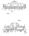
- Fig. 1 eine erfindungsgemäß ausgebildete Bodenbearbeitungsmaschine mit hinter der Bodenbearbeitungsmaschine angeordneter Packerwalze in der Vorderansicht,
- Fig. 2 einen erfindungsgemäß ausgebildeten Werkzeugkreisel mit Werkzeugen in der Vorderansicht und im Teilschnitt,
- Fig. 3 den Werkzeugkreisel gemäß Fig. 2 in der Ansicht von unten;
- Fig. 4 einen weiteren Werkzeugkreisel in der Vorderansicht und im Teilschnitt,
- Fig. 5 eine weitere erfindungsgemäß ausgebildete Bodenbearbeitungsmaschine mit hinter der Bodenbearbeitungsmaschine angeordneter Nachlaufwalze in der Vorderansicht,
- Fig. 6 das Oberteil eines Werkzeugkreisels gemäß Fig 5 ohne Bodenplatte in der Ansicht von unten,
- Fig. 7 das Oberteil des Werkzeugkreisels gemäß Fig. 6 in der Ansicht VII-VII,
- Fig. 8 das Oberteil des Werkzeugkreisels gemäß Fig. 5 in der Seitenansicht,
- Fig. 9 die Bodenplatte des Werkzeugkreisels gemäß Fig. 5 in der Draufsicht,
- Fig. 10 die Bodenplatte des Werkzeugkreisels gemäß Fig. 5 in der Seitenansicht,
- Fig. 11 der komplette Werkzeugkreisel gemäß Fig. 5 in der Seitenansicht,
- Fig. 12 der komplette Werkzeugkreisel gemäß Fig. 5 mit Bodenbearbeitungswerkzeugen in der Seitenansicht,
- Fig. 13 der Werkzeugkreisel gemäß Fig. 5 mit Bodenbebeitungswerkzeugen in der Vorderansicht im Teilschnitt,
- Fig. 14 einen Werkzeugkreisel gemäß Fig. 5 mit Bodenbearbeitungswerkzeugen in 'der Ansicht von unten,
- Fig. 15 einen weiteren erfindungsgemäß ausgebildeten Werkzeugkreisel mit Werkzeugen einer Kreiselegge in der Seitenansicht und im Schnitt,
- Fig. 16 den Werkzeugkreisel gemäß Fig. 15 in der Draufsicht,
- Fig. 17 den Werkzeugkreisel gemäß Fig. 15 in der Seitenansicht von rechts und
- Fig. 18 einen anderen erfindungsgemäßen Werkzeugkreisel mit Werkzeugen einer Kreiselegge in der Ansicht von unten.
- 1 is a front view of a tillage machine designed according to the invention with a packer roller arranged behind the tillage machine,
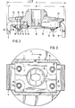
- 2 shows a tool gyroscope designed according to the invention with tools in front view and in partial section,
- 3 shows the tool gyroscope according to FIG. 2 in a view from below;
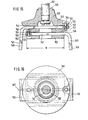
- 4 shows another tool gyroscope in front view and in partial section,
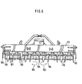
- 5 shows a further tillage machine designed according to the invention with a trailing roller arranged behind the tillage machine in the front view,
- 6 the top part of a tool gyroscope according to FIG. 5 without bottom plate in a view from below,
- 7 the top part of the tool gyroscope according to FIG. 6 in the view VII-VII,
- 8 is a side view of the upper part of the tool gyroscope according to FIG. 5,
- 9 is a top view of the base plate of the tool gyroscope according to FIG. 5,
- F ig. 10 the bottom plate of the tool top according to FIG. 5 in a side view,
- F ig. 11 the complete tool gyroscope according to FIG. 5 in a side view,
- 12 the complete tool gyroscope according to FIG. 5 with tillage tools in a side view,
- 13 of the tool rotor according to FIG. 5 with soil cultivation tools in a front view in partial section,
- Fig. 14 shows a tool gyroscope according to Fig. 5 with soil working tools in 'a view from below,
- 15 shows a further tool gyroscope designed according to the invention with tools of a rotary harrow in side view and in section,
- 16 is a top view of the tool gyroscope according to FIG. 15,
- FIG. 17 shows the tool rotor according to FIG. 15 in the Side view from the right and
- 18 shows another tool rotor according to the invention with tools of a rotary harrow in a view from below.
Die Bodenbearbeitungsmaschine kann entweder als Kreiselgrubber oder als Kreiselegge ausgebildet sein. Der wesentliche Unterschied zwischen einem Kreiselgrubber und einer Kreiselegge besteht in der Anordnung der Werkzeuge. Wenn die Werkzeugspitzen in Drehrichtung gesehen auf Griff stehen, bezeichnet man diese Maschine als Kreiselgrubber, wenn jedoch die Werkzeugspitzen.in Drehrichtung gesehen nachlaufen; d.h. schleppend angeordnet sind, spricht man von einer Kreiselegge.The tillage machine can either be designed as a rotary cultivator or as a rotary harrow. The main difference between a rotary cultivator and a rotary harrow is the arrangement of the tools. When the tool tips are on the handle when viewed in the direction of rotation, this machine is referred to as a rotary cultivator, but when the tool tips continue to run when viewed in the direction of rotation; i.e. are arranged sluggishly, one speaks of a rotary harrow.
Die Bodenbearbeitungsmachine weist das Gestell 1 auf, in dem in einer quer zur Fahrtrichtung verlaufenden Reihe nebeneinander die Werkzeugkreisel 2 angeordnet sind. Die Werkzeugkreisel 2 werden von der Zapfwelle des die Bodenbearbeitungsmaschine fortbewegenden Schleppers angetrieben, wobei die jeweils einander benachbarten Werkzeugkreisel 2 im entgegengesetzten durch den Pfeil 3 gekennzeichneten Drehsinn um aufrechte Achsen rotieren. Die Werkzeugkreisel 2 sind tellerförmig ausgebildet. An diesen Werkzeugkreiseln 2 sind die nach unten ragenden Werkzeuge 4 befestigt. Seitlich neben den jeweils äußeren Werkzeugkreiseln 2 ist das Seitenblech 5 angeordnet, welches jeweils die Verlagerung der Erde nach außen begrenzt. Hinter der Bodenbearbeitungsmaschine ist die Packerwalze 6 mit ihrem auf dem Umfang angeordneten Zacken 7 angeordnet.The tillage machine has the frame 1, in which the tool rotors 2 are arranged next to one another in a row running transversely to the direction of travel. The tool rotors 2 are driven by the power take-off of the tractor moving the tillage machine, the respectively adjacent tool rotors 2 rotating in the opposite direction of rotation indicated by the
Die Werkzeugkreisel 2 weisen radial nach außen weisende Aufnahmeöffnungen 8 für das jeweilige Befestigungsteil 9 der Werkzeuge 4 auf. Die Werkzeuge 4 weisen jeweils ein Bearbeitungsteil 10, welches den Boden bearbeitet und ein etwa rechtwinklig zu dem Bearbeitungsteil 10 abgewinkeltes Befestigungsteil 9 auf. Dieses Befestigungsteil 9 weist die beiden Bohrungen 11 auf.The tool rotors 2 have receiving
Der Werkzeugkreisel 2 besteht aus dem oberen Schmiedeteil 12, welches eine zentrale Bohrung zur Befestigung an einer Antriebswelle eines nicht dargestellten Getriebes, welches in dem Gestell 1 angeordnet ist, aufweist, und aus der an dem Schmiedeteil 12 angeschweißten Platte 13. Auf der Unterseite des Schmiedeteiles 12 des Werkzeugkreisels 2 sind jeweils zur Bildung der Aufnahmeöffnung 8 die nach unten gerichtete Stege 15 an dem Schmiedeteil einstückig angeordet. Auf der.Unterseite der Stege 15 ist die die jeweils vier sich auf der Unterseite befindlichen 15 verbindende Platte 13 aufgeschweißt. Die Platte 15 weist in ihrer Mitte eine große zentrale Bohrung 16 auf, so daß innerhalb dieser zentralen Bohrung 16 das Befestigungselement zur Sicherung des Werkzeugkreisels 2 auf der Antriebswelle angeordnet werden kann. Weiterhin weist diese Platte im Bereich jeder Aufnahmeöffnung zwei Bohrungen 17 auf, die mit den jeweiligen Bohrungen, die in dem Schmiedeteil 12 im Bereich der Aufnahmeöffnung angeordnet sind, fluchten. Weiterhin fluchten diese Bohrungen 17 mit den Bohrungen 11 in dem Befestigungsteil 9 der Werkzeuge 4, wenn das Befestigungsteil 9 der Werkzeuge 4 in diese Aufnahmeöffnungen gesteckt ist.The tool gyroscope 2 consists of the upper forged
Die Aufnahemöffnungen 8 weisen einen etwas größeren Querschnitt als das Befestigungsteil 9 des Werkzeuges auf. Somit sind die in diesen Aufnahmeöffnungen 8 angeordneten Befestigungsteile der Werkzeuge mit einem gewissen Spiel angeordnet, so daß die Werkzeuge leicht lösbar in diesen Aufnahmeöffnungen angeordnet sind. Die Befestigungsteile 9 der Werkzeuge werden durch die beiden durch die Bohrungen 11 und 17 gesteckten Bolzen 18 leicht lösbar in der Aufnahmeöffnung der Werkzeugkreisel 2 gehalten. Die Bolzen 18 sind mitels der als Splinte 19 ausgebildeten Schnellverschlüsse in den Bohrungen des Werkzeugkreisels gesichert. Die Bolzen 18 sind auf der Oberseite des Werkzeugkreisels 2 versenkt angeordnet. Die Versenkung 20 ist als Sechskant ausgebildet, so daß der sich an der Oberseite des Bolzens 18 befindliche Sechskant 21 drehfest in der jeweiligen Bohrung 17 angeordnet ist, so daß er sich nicht verdrehen kann.The receiving
Vor allem wenn die Bodenbearbeitungsmaschine auf steinigen Böden eingesetzt werden soll, ist es sinnvoll, daß auf der Unterseite des Werkzeugkreisels vor den Schnellverschlüssen 19 jeweils ein mit gestrichtelten Linien angedeuteter stehender Schutzschirm 22 angeordnet ist.Especially when the tillage machine is to be used on stony soils, it makes sense that a
Die gleiche Schutzwirkung kann dadurch erreicht werden, daß die Splinte 19 ebenfalls in einer Versenkung, die in der Platte 13 angeordnet sein könnte, angeordnet sind.The same protective effect can be achieved in that the
Die Werkzeugkreisel 2 weisen einen Durchmesser D auf, der in etwa dem Abstand A zwischen den oberen äußeren Teilen der Werkzeuge 4 entspricht. Hierzu weisen die Werkzeugkreisel 2 den schmalen umlaufenden Ring 23 auf. Somit wird erreicht, daß zwischen den einzelnen nebeneinander angeordneten Werkzeugkreiseln 2 nur ein kleiner Abstand B sich befindet, so daß sich keine Steine zwischen den einzelnen nebeneinander angeordneten Werkzeugkreiseln 2 einklemmen können. Somit können keine Beschädigungen an den Werkzeugkreiseln 2 durch Einklemmen von Steinen zwischen diesen auftreten.The tool rotors 2 have a diameter D which corresponds approximately to the distance A between the upper outer parts of the
Der Werkzeugkreisel gemäß Fig. 4 unterscheidet sich von dem Werkzeugkreisel gemäß Fig. 2 lediglich durch die Ausbildung der Sicherungsbolzen. Diese Sicherungsbolzen 24 sind als Schrauben ausgebildet, wobei die Schrauben auf der Unterseite des Werkzeugkreisels durch Muttern 25 gesichert werden. Vorzugsweise sind diese Muttern 25 als selbstsichernde Muttern ausgebildet. Da diese Sicherungsschrauben relativ klein demensioniert ausgebildet werden können, können diese Sicherungsschrauben, falls der Sechskant der Muttern durch Bodenberührung bzw. durch Aufprall von Steinen beschädigt bzw. abgeschliffen ist, in einfacher Weise durch Abschlagen mit einem Meißel entfernt werden. Somit lassen sich auch bei diesem Ausführungsbeispiel die Werkzeuge 4 in sehr kurzer Zeit in einfacher Weise erneuern.The tool gyro according to FIG. 4 differs from the tool gyroscope according to FIG. 2 only in the design of the securing bolts. These securing
Um die Werkzeuge 4 austauschen zu können, sind in einfacher Weise die Schnellverschlüsse aus den Bolzen zu entfernen. Da die Bolzen 18 und 24 mit einem Spiel in ihren Bohrungen und in dem Befestigungsteil 9 angeordnet sind, lassen sie sich einfach ohne große Kraftaufwendung entfernen. Da die Befestigungsteile 9 der Werkzeuge 4 mit einem gewissen Spiel in den Aufnahmeöffnungen 8 der Werkzeugkreisel 2 angeordnet werden können, können die Werkzeuge sehr einfach aus den Aufnahmeöffnungen 8 der Werkzeugkreisel 2 herausgezogen werden. Anschließend werden die Befestigungsteile der neuen Werkzeuge 4 einfach von außen in die Aufnahmeöffnung 8 hineingesteckt. Anschließend werden die Werkzeuge 2 durch Hineinstecken der Bolzen 18 oder 24 in die dafür vorgesehenen Bohrungen in dem Werkzeugkreisel 2 und in dem Befestigungsteil 9 der Werkzeuge 4 gesichert. Diese Bolzen 18 oder 24 werden dann entweder durch einen Splint 19 oder durch eine Mutter 25 gesichert. In kürzester Zeit können also die Werkzeuge 4 ohne große Kraftanstrengung ausgetauscht werden. Diese Austauscharbeiten sind sogar von dem Landwirt auf dem Acker vorzunehmen.In order to be able to replace the
Die als Kreiselegge oder als Kreiselgrubber gemäß Fig. 5 ausgebildete Bodenbearbeitungsmaschine weist das Gestell 101 auf, in dem in einer quer zur Fahrtrichtung verlaufenden Reihe nebeneinander die Werkzeugkreisel 102 angeordnet sind. Die Werkzeugkreisel 102 werden von der Zapfwelle des die Bodenbearbeitungsmaschine fortbewegenden Schleppers angetrieben, wobei die jeweils einander benachbarten Werkzeugkreisel 102 im entgegengesetzten durch den Pfeil 103 gekennzeichneten Drehsinn um aufrechte Achsen rotierend angetrieben werden. Die Werkzeuge 102 sind tellerförmig ausgebildet. An diesen Werkzeugkreiseln 102 sind die nach unten ragenden als Messer bzw. als Zinken ausgebildeten Bodenbearbeitungswerkzeuge 104 befestigt. Seitlich neben den jeweils äußeren Werkzeugkreiseln 102 ist ein Seitenblech 105 angeordnet, welches jeweils die Verlagerung der Erde nach außen begrenzt. Hinter der Bodenbearbeitungsmaschine ist die Packerwalze-106.mit ihrem auf dem Umfang angeordneten Zacken 107 angeordnet.5 has the
Die Werkzeugkreisel 102 weisen radial nach außen gerichtet Aufnahmeöffnungen 108 für das jeweilige Befestigungsteil 109 der Bodenbearbeitungswerkzeuge 104 auf. Die Bodenbearbeitungswerkzeuge 104 weisen jeweils ein Bearbeitungsteil 110, welches den Boden bearbeitet und ein etwa rechtwinklig zu dem Bodenbearbeitungsteil 110 abgewinkeltes Befestigungsteil 109 auf. Dieses Befestigungsteil 109 weist eine Bohrung 111 auf.The
Jeder Werkzeugkreisel 102 besteht aus dem oberen Schmiedeteil 112, welches eine zentral.e Bohrung zur Befestigung an einer Antriebswelle der nicht dargestellten Getriebe, welche in dem Gestell 101 angeordnet sind, aufweist, und aus der an dem Schmiedeteil 112 angeschweißten Bodenplatte 113. Auf der Unterseite des Schmiedeteiles 112 der Werkzeugkreisel 102 sind jeweils zur Bildung der Aufnahmeöffnung 108 die nach unten gerichteten Stege 115 an dem Schmiedeteil 112 einstückig angeordnet. Auf der Unterseite der Stege 115 ist die die Stege jeweils miteinander verbindende Platte 113 aufgeschweißt. Die Platte 113 weist in ihrer Mitte eine große zentrale Bohrung 116 auf, so daß innerhalb dieser zentralen Bohrung 116 das Befestigungselement zur Sicherung des Werkzeugkreisels 102 auf der Antriebswelle des Werkzeugkreisels angeordnet werden kann. Weiterhin weist diese Platte im Bereich jeder Aufnahmeöffnung die Bohrung 117 auf, die mit der jeweiligen Bohrung, die in dem Schmiedeteil 112 Im Bereich der Aufnahmeöffnung angeordnet ist, fluchten. Weiterhin fluchtet diese Bohrung 117 mit der jeweiligen Bohrung 111 in dem Befestigungsteil 109 der Werkzeuge 104, wenn das Befestigungsteil 109 der Werkzeuge 104 in diese Aufnahmeöffnungen gesteckt ist.Each
Die Aufnahmeöffnungen 108 weisen einen größeren Querschnitt als das Befestigungsteil 109 des Bodenbearbeitungswerkzeuges 4 auf. Somit sind die in diesen Aufnahmeöffnungen 108 angeordneten Befestigungsteile 109 der Werkzeuge 104 mit einem gewissen Spiel angeordnet, so daß die Bodenbearbeitungswerkzeuge 104 leicht lösbar in diesen Aufnahmeöffnungen angeordnet sind. Die Befestigungsteile 109 der Werkzeuge werden durch die durch die Bohrungen 111 und 117 gesteckten Bolzen 118 leicht lösbar in der Aufnahmeöffnung der Werkzeugkreisel 102 gehalten. Die Bolzen 118 sind mittels der als Splinte 119 ausgebildeten Stellverschlüsse in den Bohrungen des Werkzeugkreisels 102 gesichert.The receiving
Die Aufnahmeöffnung 108 weist in ihrem äußeren radialen Bereich 120 von der Mitte 121 der Aufnahmeöffnung 108 in tangentialer Richtung gesehen eine wesentlich größere Höhe E als die Höhe F der Verfestigungsteile 109 der Bodenbearbeitungswerkzeuge 104 auf. Die Aufnahmeöffnungen 108 in den Werkzeugkreiseln 102 für die Befestigungsteile 108 erstrecken sich jeweils bis zur Mitte 122 des Werkzeugkreisels 102 und die Befestigungsteile 109 der Bodenbearbeitungswerkzeuge 104 ragen ebenfalls bis zur Mitte 122 des Werkzeugkreisels 102 in die Aufnahmeöffnungen 108 hinein. Hierzu weist das Befestigungsteil auf seiner dem Bodenbearbeitungsteil 110 abgewandten Seite 123 die Aussparung 124 auf, die der Kontur der Nabe 125 des Werkzeugkreisels 102 entspricht. Die durch die Aussparung 124 entstandenen Zungen 126 des Befestigungsteiles 109 erstrecken sich seitlich der Nabe 124 bis zur Mitte 122 des Werkzeugkreisels 102. Der größere äußere Querschnitt 127 der Aufnahmeöffnung 108 erstreckt sich über mehr als die halbe Länge L der Aufnahmeöffnung 108 oder des Befestigungsteiles 109, jedoch nicht mehr als über vier Fünftel der Länge L der Aufnahmeöffnung 108 oder des Befestigungsteiles 109 des Bodenbearbeitungswerkzeuges 104.The receiving
Die Aufnahmeöffnungen 108 in den Werkzeugkreiseln 102 für die Aufnahme des Befestigungsteiles 109 des Bodenbearbeitungswerkzeuges 104 weisen in ihrem der Mitte 122 des Werkzeugkreisels 102 nächstliegenden Bereich 128 einen Querschnitt 129 auf, der zumindest annähernd dem Querschnitt der Befestigungsteile 109 der Bodenbearbeitungswerkzeuge 104 entspricht. In einem Abstand von der Mitte 122 des Werkzeugkreisels 102 weist die Aufnahmeöffnung 108 einen größeren Querschnitt 127 auf. Dieser größere Querschnitt 127 der Aufnähmeöffnung 108 vergrößert sich von der Mitte 121 der Aufnahmeöffnung 108 in tangentialer Richtung, vor allem in den seitlichen Bereichen der Aufnahmeöffnung. Die obere Fläche 130 der in Drehrichtung 103 gesehen hinteren Hälfte 131 der Aufnahmeöffnung 108 verläuft etwa von der Mitte 121 der Aufnahmeöffnung 108 schräg nach oben und die untere Fläche 132 der in Drehrichtung 103 gesehen vorderen Hälfte 133 der Aufnahmeöffnung 108 verläuft von der Mitte 121 der Aufnahmeöffnung 108 schräg nach unten. Weiterhin verlaufen jeweils von der Mitte 121 der Aufnahmeöffnung 108 aus die oberen und unteren Flächen 130, 132, 134 und 135 der Aufnahmeöffnung 108 jeweils schräg nach oben oder unten. Somit weist die Aufnahmeöffnung 108 von der Seite aus in radialer Richtung oder in Richtung der Drehachse des Werkzeugkreisels 102 gesehen einen etwa X-förmigen Querschnitt 127 auf, wobei dieser Querschnitt 127 sich von außen nach innen in radialer Richtung erstreckt und in einem Abstand von der Drehachse des Werkzeugkreisels 102 in einem zumindest annähernd dem Querschnitt des inneren Teiles 126 des Befestigungsteiles 109 des Werkzeuges 104 entsprechenden Querschnitt 129 übergeht. In der Mitte 121 der Aufnahmeöffnung 108 befinden sich jeweils auf der unteren und der oberen Seite der Aufnahmeöffnung 108 die sich jeweils in radialer Richtung erstreckenden Stege 136. Der senkrechte Abstand zwischen dem oberen und dem unteren Steg 136 entspricht der Höhe F des Befestigungsteiles 109. Somit stützt sich im normalen Betrieb das Befestigungsteil 109 des jeweiligen Bodenbearbeitungswerkzeuges 104 an diesen Stegen 136 ab und wird von den in den inneren Querschnitt 127 fassenden Zungen 126 des Befestigungsteiles 109 in die in Fig. 8 mit durchzogenen Linien dargestellte Position gehalten.The receiving
Trifft nun das Bodenbearbeitungswerkzeug 104 auf ein im Boden befindliches Hindernis, wie Steine, Wurzeln etc. so kann das Befestigungsteiles 109 des Bodenbearbeitungserkzeuges 104 aufgrund der X-förmigen AusblJJung des äußeren Bereiches der Aufnahmeöffnung 108 sich innerhalb des äußeren Bereiches der Aufnahmeöffnung 108 in sich federnd verdrehen, so daß der Bearbeitungsteil 110 des Bodenbearbeitungswerkzeuges 104 in die in mit strichpunktierten Linien dargestellte Position 137 schwenken kann.If the
In den oberen Flächen 130 und 134 der Aufnahmeöffnungen 108 sind die Nutenförmigen Vertiefungen 138 mit durch Schmieden angebracht. In diesen Vertiefungen 138 fassen die auf dem Befestigungsteil 109 angeordneten und erhöht ausgebildeten Erhebungen. Hierdurch wird erreicht, daß man die Bodenbearbeitungswerkzeuge auf die Drehrichtung der Werkzeugkreisel 102 bezogen immer richtig montiert. Um verschiedene Werkzeuge 104 vorschriftsmäßig zu montieren, kann der Abstand der Vertiefungen 138 von der Mitte der Aufnahmeöffnungen bei den linksdrehenden Werkzeugkreiseln ein anderes Maß als der Abstand bei den rechtsdrehenden Werkzeugkreiseln aufweisen. Weiterhin sind die Vertiefungen 138 bei den linksdrehenden Werkzeugkreiseln 102 spiegelbildich zu den beiden rechtsdrehenden Werkzeugkreiseln 102 angeordnet.In the
Der Werkzeugkreisel 140 gemäß den Fig. 15 bis 17 ist auf der drehbar angetriebenen Welle 141 angeordnet. Die Welle 141 der Kreiselegge wird über ein Getriebe von der Zapfwelle des die Kreiselegge ziehenden Schleppers angetrieben. Die Kreiselegge weist mehrere in einer quer zur Fahrtrichtung verlaufenden Reihe nebeneinander angeordnete Wellen 141 auf, an denen die Werkzeugkreisel 140 befestigt sind. Die Werkzeugkreisel 140 sind in der Draufsicht gesehen tellerförmig ausgebildet. An diesen Werkzeugkreiseln 140 sind die nach unten ragenden als Zinken ausgebildeten Bodenbearbeitungswerkzeuge 142 und 143 befestigt. Die Werkzeugkreisel 140 weisen radial nach außen gerichtete Aufnahmeöffnungen 144 und 145 für das jeweilige Befestigungsteil 146 und 147 der Zinken 142 und 143 auf. Die Bodenbearbeitungszinken 142 und 143 weisen jeweils das schräg nach unten gerichtete Bearbeitungsteil 148 sowie ein etwa rechtwinklig zu dem Bearbeitungsteil 148 abgewinkeltes Befestigungsteil 146 und 147 auf.The
Jeder Werkzeugkreisel 140 besteht aus dem oberen Schmiedeteil 149, welches eine zentrale Bohrung 150 zur Befestigung des Werkzeugkreisels 140 an der Antriebswelle 141 des nicht dargestellten Getriebes, aufweist. Des weiteren besteht dieser Werkzeugkreisel zusätzlich aus den an dem Schmiedeteil 149 angeschweißten Bodenplatten 151 und 152. Die Werkzeugkreisel 140 weisen für jedes Befestigungsteil 146 und 147 der Bodenbearbeitungszinken 142 und 143 die übereinander liegenden Aufnahmeöffnungen 144 und 145 für die Befestigungsteile 146 und 147 der Bodenbearbeitungszinken 142 und 143 auf. Die Aufnahmeöffnungen 144 und 145 für die Befestigungsteile 146 und 147 der Bodenbeabeitungszinken 142 und 143 erstrecken sich über den gesamten Durchmesser D des Werkzeugkreisels 140. Am Anfang 153 weisen die Befestigungsteile 146 und 147 die Bohrung 154 auf. Durch diese Bohrung 154 ist jeweils ein Schraubbolzen 155 gesteckt. Dieser Schraubbolzen 155 ist ebenfalls durch die sich im Werkzeugkreisel 140 befindliche Bohrung 156 gesteckt, so daß die Werkzeuge 142 und 143 durch diesen Schraubbolzen 155 jeweils im Werkzeugkreisel 140 gesichert und gehalten werden.Each
Im Bereich des Anfanges 153 des Befestigungsteiles 146 bzw. 147 der Bodenbearbeitungszinken 142 und 143 weist die Aufnahmeöffnung 144 bzw. 145 einen dem Befestigungsteil 146 bzw. 147 entsprechenden Querschnitt auf, wobei der Anfang des Befestigungsteiles jeweils mit einem kleinen Spiel in diesen Teilen der Aufnahmeöffnung einfaßt.In the area of the beginning 153 of the
Die Aufnahmeöffnungen 144 und 145 erweitern sich in Richtung der des Bodenbearbeitungsteiles 148 zugewandten Seite auf ihrer Ober- und Unterseite in den seitlichen Bereiches der Aufnahmeöffnungen. In der Mitte der Aufnahmeöffnung weisen die Aufnahmeöffnungen 144 und 145 einen Abstand zueinander auf, der etwa der Höhe des Befestigungsteiles 146 und 147 der Bodenbearbeitungszinken 142 und 143 entspricht, damit die Bodenbearbeitungszinken 142 und 143 bzw. deren Befestigungsteile 146 und 147 eine Anlagefläche haben. Durch die Erweiterung im seitlichen Bereich der Aufnahmeöffnung ergibt sich ein X-förmiger Querschnitt der Aufnahmeöffnung, wobei sich dieser stetig erweiternde X-förmige Querschnitt sich zumindest über zwei Drittel der Länge, die in etwa dem Durchmesser D des Werkzeugkreiseles 140 im Bereich der Aufnahmeöffnungen entspricht, erstreckt. Die Aufnahmeöffnungen 144 und 145 des Werkzeugkreisels 140 sind untereinanderliegend angeordnet.The receiving
Durch diese Art der Ausbildung der Aufnahmeöffnungen 144 und 145, die einen sich in Richtung des Bearbeitungsteiles 148 der Bodenbearbeitungszinken 142 und 143 sich stetig erweiternden X-förmigen Querschnitt aufweist, wobei die Erweiterung sich im wesentlichen von dem Beginn des Befestigungsteiles in Richtung des Bodenbearbeitungsteiles im seitlichen Bereich sowie sich von der Mitte der Aufnahmeöffnung nach außen erstreckend sich erweitert, wird erreicht, daß sich das Befestigungsteil 146 bzw. 147 innerhalb der Aufnahmeöffnung um die Mittelachse 157 der jeweiligen Aufnahmeöffnung 144 und 145 federnd verdrehen kann. Hierdurch können die Bearbeitungsteile 148 der . Bodenbearbeitungszinken 142 und 143 entgegen der Fahrtrichtung elastisch ausweichen und wieder in ihre Normalposition nach dem Überschreiten des im Boden festsitzenden Hindernisses zurückfedern.This type of design of the receiving
Der Werkzeugkreisel 158 gemäß Fig. 4 unterscheidet sich von dem Werkzeugkreisel 140 gemäß den Fig. 1 bis 3 im wesentlichen dadurch, daß die Aufnahmeöffnungen 159 und 160 für die Befestigungsteile 161 der Bodenbearbeitungszinken 162 nicht untereinanderliegend, sondern in der Draufsicht bzw. in der Ansicht von unten nebeneinanderliegend in dem Werkzeugkreisel 158 angeordnet sind. Die Bodenbearbeitungszinken 162 werden von den die Befestigungsteile 161 der Bodenbearbeitungszinken 162 sowie dem Werkzeugkreisel 158 durchsetzenden Bolzen 163 gehalten. Die Aufnahmeöffnungen 159 und 160 für die Aufnahme der Befestigungsteile 161 der Bodenbearbeitungszinken 162 erstrecken sich etwa über den gesamten Durchmesser D des Werkzeugkreisel 158. Des ![]()
![]()
Claims (24)
Applications Claiming Priority (6)
| Application Number | Priority Date | Filing Date | Title |
|---|---|---|---|
| DE3527580 | 1985-08-01 | ||
| DE19853527580 DE3527580A1 (en) | 1985-08-01 | 1985-08-01 | Ground-working machine |
| DE3543554 | 1985-12-10 | ||
| DE19853543554 DE3543554A1 (en) | 1985-12-10 | 1985-12-10 | Cultivating machine |
| DE19863622530 DE3622530A1 (en) | 1986-07-04 | 1986-07-04 | Ground-working machine |
| DE3622530 | 1986-07-04 |
Publications (3)
| Publication Number | Publication Date |
|---|---|
| EP0211276A2 true EP0211276A2 (en) | 1987-02-25 |
| EP0211276A3 EP0211276A3 (en) | 1987-08-19 |
| EP0211276B1 EP0211276B1 (en) | 1989-06-28 |
Family
ID=27193361
Family Applications (1)
| Application Number | Title | Priority Date | Filing Date |
|---|---|---|---|
| EP86109591A Expired EP0211276B1 (en) | 1985-08-01 | 1986-07-14 | Soil-tilling implement |
Country Status (2)
| Country | Link |
|---|---|
| EP (1) | EP0211276B1 (en) |
| DE (1) | DE3664088D1 (en) |
Cited By (14)
| Publication number | Priority date | Publication date | Assignee | Title |
|---|---|---|---|---|
| EP0258645A1 (en) * | 1986-08-29 | 1988-03-09 | Amazonen-Werke H. Dreyer GmbH & Co. KG | Soil-working implement |
| GB2200826B (en) * | 1986-11-07 | 1991-01-16 | Dowdeswell Eng Co Ltd | Cultivator blade mounting |
| EP0761079A1 (en) * | 1995-09-01 | 1997-03-12 | Rabewerk GmbH + Co. | Soil working machine |
| EP0891687A1 (en) * | 1997-07-18 | 1999-01-20 | Kuhn S.A. | Detachable tool for soil working machine |
| EP0891688A1 (en) | 1997-07-18 | 1999-01-20 | Kuhn S.A. | Improved and quick agricultural machine tool fixing |
| AT405592B (en) * | 1992-04-02 | 1999-09-27 | Poettinger Ohg Alois | Circular harrow |
| FR2789542A1 (en) * | 1999-02-11 | 2000-08-18 | Tiverton Limited | Rotating web splitting assembly, comprises a simplified shearing tooth attachment mechanism |
| FR2789543A1 (en) * | 1999-02-11 | 2000-08-18 | Tiverton Limited | Tool carrying fitment for a harrow comprises counter-plate screwed to tool-carrying plate with recess which receives tool with corresponding profile |
| EP1082889A1 (en) * | 1999-09-08 | 2001-03-14 | MASCHIO S.p.A. | A system for the rapid coupling of blades for rotary harrows |
| FR2802385A1 (en) * | 1999-12-21 | 2001-06-22 | Eurosystems Spa | Base plate, to carry tools in harrow, is formed as metallic plate, with series of impressions, equally spaced around periphery, and formed in two parts |
| EP1208729A1 (en) * | 2000-11-24 | 2002-05-29 | F. W. Pettit Limited | Improvements in or relating to power harrows |
| EP1287728A1 (en) * | 2001-08-24 | 2003-03-05 | Rabe Agrarsysteme GmbH & Co. KG | Soil working machine with rotary tines |
| EP1419682A1 (en) * | 2002-11-12 | 2004-05-19 | Frandent di Ezio Bruno | Tool holder assembly for machine for tilling the soil and tool for said assembly |
| WO2016199163A1 (en) * | 2015-06-12 | 2016-12-15 | Tirth Agro Technology Pvt. Ltd. | A quick fit mechanism for power harrow blade |
Citations (8)
| Publication number | Priority date | Publication date | Assignee | Title |
|---|---|---|---|---|
| NL262937A (en) * | 1960-04-11 | 1900-01-01 | ||
| US3380786A (en) * | 1965-08-20 | 1968-04-30 | Kongskilde Maskinfabrik As | Bolt connection particularly for fixing a harrow tooth to a supporting bar |
| FR2090356A1 (en) * | 1970-05-28 | 1972-01-14 | Lely Nv C Van Der | |
| FR2208588A1 (en) * | 1972-12-04 | 1974-06-28 | Lely Nv C Van Der | |
| US3887014A (en) * | 1970-05-19 | 1975-06-03 | Lely Cornelis V D | Soil cultivators |
| FR2278232A1 (en) * | 1974-07-18 | 1976-02-13 | Lely Nv C Van Der | MACHINE FOR WORKING THE SOIL |
| FR2310687A1 (en) * | 1975-05-16 | 1976-12-10 | Anjou Atel Mec | Clamp for harrow tine on machine chassis - has end of tine bolted to L-shaped bracket with slot and spring tangs |
| FR2447134A1 (en) * | 1979-01-29 | 1980-08-22 | Kuhn Sa | Tractor-drawn rotary harrow - has tools fixed to transmission component supports and has spring-mounted baffles at either side |
-
1986
- 1986-07-14 EP EP86109591A patent/EP0211276B1/en not_active Expired
- 1986-07-14 DE DE8686109591T patent/DE3664088D1/en not_active Expired
Patent Citations (8)
| Publication number | Priority date | Publication date | Assignee | Title |
|---|---|---|---|---|
| NL262937A (en) * | 1960-04-11 | 1900-01-01 | ||
| US3380786A (en) * | 1965-08-20 | 1968-04-30 | Kongskilde Maskinfabrik As | Bolt connection particularly for fixing a harrow tooth to a supporting bar |
| US3887014A (en) * | 1970-05-19 | 1975-06-03 | Lely Cornelis V D | Soil cultivators |
| FR2090356A1 (en) * | 1970-05-28 | 1972-01-14 | Lely Nv C Van Der | |
| FR2208588A1 (en) * | 1972-12-04 | 1974-06-28 | Lely Nv C Van Der | |
| FR2278232A1 (en) * | 1974-07-18 | 1976-02-13 | Lely Nv C Van Der | MACHINE FOR WORKING THE SOIL |
| FR2310687A1 (en) * | 1975-05-16 | 1976-12-10 | Anjou Atel Mec | Clamp for harrow tine on machine chassis - has end of tine bolted to L-shaped bracket with slot and spring tangs |
| FR2447134A1 (en) * | 1979-01-29 | 1980-08-22 | Kuhn Sa | Tractor-drawn rotary harrow - has tools fixed to transmission component supports and has spring-mounted baffles at either side |
Cited By (17)
| Publication number | Priority date | Publication date | Assignee | Title |
|---|---|---|---|---|
| EP0258645A1 (en) * | 1986-08-29 | 1988-03-09 | Amazonen-Werke H. Dreyer GmbH & Co. KG | Soil-working implement |
| GB2200826B (en) * | 1986-11-07 | 1991-01-16 | Dowdeswell Eng Co Ltd | Cultivator blade mounting |
| AT405592B (en) * | 1992-04-02 | 1999-09-27 | Poettinger Ohg Alois | Circular harrow |
| EP0761079A1 (en) * | 1995-09-01 | 1997-03-12 | Rabewerk GmbH + Co. | Soil working machine |
| EP0891687A1 (en) * | 1997-07-18 | 1999-01-20 | Kuhn S.A. | Detachable tool for soil working machine |
| EP0891688A1 (en) | 1997-07-18 | 1999-01-20 | Kuhn S.A. | Improved and quick agricultural machine tool fixing |
| FR2766054A1 (en) * | 1997-07-18 | 1999-01-22 | Kuhn Sa | REMOVABLE TOOL FOR A FLOOR WORKING MACHINE |
| FR2789543A1 (en) * | 1999-02-11 | 2000-08-18 | Tiverton Limited | Tool carrying fitment for a harrow comprises counter-plate screwed to tool-carrying plate with recess which receives tool with corresponding profile |
| FR2789542A1 (en) * | 1999-02-11 | 2000-08-18 | Tiverton Limited | Rotating web splitting assembly, comprises a simplified shearing tooth attachment mechanism |
| EP1082889A1 (en) * | 1999-09-08 | 2001-03-14 | MASCHIO S.p.A. | A system for the rapid coupling of blades for rotary harrows |
| FR2802385A1 (en) * | 1999-12-21 | 2001-06-22 | Eurosystems Spa | Base plate, to carry tools in harrow, is formed as metallic plate, with series of impressions, equally spaced around periphery, and formed in two parts |
| EP1208729A1 (en) * | 2000-11-24 | 2002-05-29 | F. W. Pettit Limited | Improvements in or relating to power harrows |
| EP1287728A1 (en) * | 2001-08-24 | 2003-03-05 | Rabe Agrarsysteme GmbH & Co. KG | Soil working machine with rotary tines |
| EP1419682A1 (en) * | 2002-11-12 | 2004-05-19 | Frandent di Ezio Bruno | Tool holder assembly for machine for tilling the soil and tool for said assembly |
| WO2016199163A1 (en) * | 2015-06-12 | 2016-12-15 | Tirth Agro Technology Pvt. Ltd. | A quick fit mechanism for power harrow blade |
| GB2555267A (en) * | 2015-06-12 | 2018-04-25 | Tirth Agro Tech Pvt Ltd | A quick fit mechanism for power harrow blade |
| GB2555267B (en) * | 2015-06-12 | 2021-06-23 | Tirth Agro Tech Pvt Ltd | A quick fit mechanism for power harrow blade |
Also Published As
| Publication number | Publication date |
|---|---|
| EP0211276A3 (en) | 1987-08-19 |
| DE3664088D1 (en) | 1989-08-03 |
| EP0211276B1 (en) | 1989-06-28 |
Similar Documents
| Publication | Publication Date | Title |
|---|---|---|
| EP0211276B1 (en) | Soil-tilling implement | |
| EP0033950A1 (en) | Power take-off soil treatment implement | |
| DE2617865C2 (en) | ||
| DE3541490A1 (en) | TILLAGE MACHINE | |
| DE2728656C3 (en) | Earthworking tool for seed drills | |
| DE7617432U1 (en) | TRACTOR-WORKED TILLAGE MACHINE | |
| EP0150731B1 (en) | Gardening hand tool for tilling soil | |
| DE3446312C2 (en) | ||
| DE2850894C2 (en) | ||
| CH630225A5 (en) | Rotary harrow. | |
| DE3338284C2 (en) | ||
| DE2833399A1 (en) | Power-driven rotary cultivator - has tool carrier with pivoted side screen including skids at bottom | |
| DE3409110A1 (en) | GROUND MACHINING MACHINE, IN PARTICULAR Harrow | |
| EP0129047B1 (en) | Agricultural soil-working implement with a rotary tine carrying shaft | |
| EP0081600B1 (en) | Rotary harrow | |
| EP0293675B1 (en) | Soil-working implement | |
| DE2849868C3 (en) | Tillage machine | |
| EP0258645B1 (en) | Soil-working implement | |
| DE3543554A1 (en) | Cultivating machine | |
| EP0118868A2 (en) | Soil-working implement | |
| DE2648293C2 (en) | Tine arrangement on a soil cultivation implement | |
| DE3345774A1 (en) | TILLAGE MACHINE | |
| EP0224708B1 (en) | Tools for a soil working machine | |
| DE202015000741U1 (en) | Knife for a tillage machine | |
| DE4124330C2 (en) | Soil cultivation machine, in particular chopping and weeding machine |
Legal Events
| Date | Code | Title | Description |
|---|---|---|---|
| PUAI | Public reference made under article 153(3) epc to a published international application that has entered the european phase |
Free format text: ORIGINAL CODE: 0009012 |
|
| AK | Designated contracting states |
Kind code of ref document: A2 Designated state(s): DE FR GB IT NL |
|
| PUAL | Search report despatched |
Free format text: ORIGINAL CODE: 0009013 |
|
| AK | Designated contracting states |
Kind code of ref document: A3 Designated state(s): DE FR GB IT NL |
|
| 17P | Request for examination filed |
Effective date: 19871119 |
|
| 17Q | First examination report despatched |
Effective date: 19880322 |
|
| GRAA | (expected) grant |
Free format text: ORIGINAL CODE: 0009210 |
|
| AK | Designated contracting states |
Kind code of ref document: B1 Designated state(s): DE FR GB IT NL |
|
| GBT | Gb: translation of ep patent filed (gb section 77(6)(a)/1977) | ||
| REF | Corresponds to: |
Ref document number: 3664088 Country of ref document: DE Date of ref document: 19890803 |
|
| ET | Fr: translation filed | ||
| ITF | It: translation for a ep patent filed |
Owner name: STUDIO JAUMANN |
|
| PLBE | No opposition filed within time limit |
Free format text: ORIGINAL CODE: 0009261 |
|
| STAA | Information on the status of an ep patent application or granted ep patent |
Free format text: STATUS: NO OPPOSITION FILED WITHIN TIME LIMIT |
|
| 26N | No opposition filed | ||
| ITTA | It: last paid annual fee | ||
| REG | Reference to a national code |
Ref country code: GB Ref legal event code: IF02 |
|
| PGFP | Annual fee paid to national office [announced via postgrant information from national office to epo] |
Ref country code: GB Payment date: 20050415 Year of fee payment: 20 |
|
| PG25 | Lapsed in a contracting state [announced via postgrant information from national office to epo] |
Ref country code: IT Free format text: LAPSE BECAUSE OF NON-PAYMENT OF DUE FEES;WARNING: LAPSES OF ITALIAN PATENTS WITH EFFECTIVE DATE BEFORE 2007 MAY HAVE OCCURRED AT ANY TIME BEFORE 2007. THE CORRECT EFFECTIVE DATE MAY BE DIFFERENT FROM THE ONE RECORDED. Effective date: 20050714 |
|
| PGFP | Annual fee paid to national office [announced via postgrant information from national office to epo] |
Ref country code: NL Payment date: 20050715 Year of fee payment: 20 |
|
| PGFP | Annual fee paid to national office [announced via postgrant information from national office to epo] |
Ref country code: FR Payment date: 20050728 Year of fee payment: 20 |
|
| PGFP | Annual fee paid to national office [announced via postgrant information from national office to epo] |
Ref country code: DE Payment date: 20050731 Year of fee payment: 20 |
|
| REG | Reference to a national code |
Ref country code: GB Ref legal event code: PE20 |
|
| PG25 | Lapsed in a contracting state [announced via postgrant information from national office to epo] |
Ref country code: GB Free format text: LAPSE BECAUSE OF EXPIRATION OF PROTECTION Effective date: 20060713 |
|
| PG25 | Lapsed in a contracting state [announced via postgrant information from national office to epo] |
Ref country code: NL Free format text: LAPSE BECAUSE OF EXPIRATION OF PROTECTION Effective date: 20060714 |
|
| NLV7 | Nl: ceased due to reaching the maximum lifetime of a patent |
Effective date: 20060714 |