EP0211034B1 - Verfahren und vorrichtung zur erhöhung der turbulenz in einem vom gas beanschlagten schall niedriger frequenz - Google Patents
Verfahren und vorrichtung zur erhöhung der turbulenz in einem vom gas beanschlagten schall niedriger frequenz Download PDFInfo
- Publication number
- EP0211034B1 EP0211034B1 EP86900880A EP86900880A EP0211034B1 EP 0211034 B1 EP0211034 B1 EP 0211034B1 EP 86900880 A EP86900880 A EP 86900880A EP 86900880 A EP86900880 A EP 86900880A EP 0211034 B1 EP0211034 B1 EP 0211034B1
- Authority
- EP
- European Patent Office
- Prior art keywords
- resonator
- gas
- tubular
- sound
- open end
- Prior art date
- Legal status (The legal status is an assumption and is not a legal conclusion. Google has not performed a legal analysis and makes no representation as to the accuracy of the status listed.)
- Expired - Lifetime
Links
- 238000000034 method Methods 0.000 title claims abstract description 24
- 239000007789 gas Substances 0.000 claims description 37
- 239000007788 liquid Substances 0.000 claims description 16
- 239000012530 fluid Substances 0.000 claims description 6
- 239000000203 mixture Substances 0.000 claims description 2
- 239000000843 powder Substances 0.000 claims description 2
- 238000007599 discharging Methods 0.000 claims 1
- 239000003546 flue gas Substances 0.000 description 24
- UGFAIRIUMAVXCW-UHFFFAOYSA-N Carbon monoxide Chemical compound [O+]#[C-] UGFAIRIUMAVXCW-UHFFFAOYSA-N 0.000 description 20
- 238000002485 combustion reaction Methods 0.000 description 11
- 239000000654 additive Substances 0.000 description 9
- 239000002002 slurry Substances 0.000 description 8
- 238000006243 chemical reaction Methods 0.000 description 7
- 239000002245 particle Substances 0.000 description 7
- VTYYLEPIZMXCLO-UHFFFAOYSA-L Calcium carbonate Chemical compound [Ca+2].[O-]C([O-])=O VTYYLEPIZMXCLO-UHFFFAOYSA-L 0.000 description 6
- 239000000446 fuel Substances 0.000 description 5
- GNTDGMZSJNCJKK-UHFFFAOYSA-N divanadium pentaoxide Chemical compound O=[V](=O)O[V](=O)=O GNTDGMZSJNCJKK-UHFFFAOYSA-N 0.000 description 4
- 239000000126 substance Substances 0.000 description 4
- 230000000996 additive effect Effects 0.000 description 3
- 235000010216 calcium carbonate Nutrition 0.000 description 3
- 229910000019 calcium carbonate Inorganic materials 0.000 description 3
- 239000007791 liquid phase Substances 0.000 description 3
- 238000004519 manufacturing process Methods 0.000 description 3
- 230000004048 modification Effects 0.000 description 3
- 238000012986 modification Methods 0.000 description 3
- AXCZMVOFGPJBDE-UHFFFAOYSA-L calcium dihydroxide Chemical compound [OH-].[OH-].[Ca+2] AXCZMVOFGPJBDE-UHFFFAOYSA-L 0.000 description 2
- 239000000920 calcium hydroxide Substances 0.000 description 2
- 235000011116 calcium hydroxide Nutrition 0.000 description 2
- 229910001861 calcium hydroxide Inorganic materials 0.000 description 2
- 239000003054 catalyst Substances 0.000 description 2
- 150000001875 compounds Chemical class 0.000 description 2
- 238000001704 evaporation Methods 0.000 description 2
- 239000000945 filler Substances 0.000 description 2
- 239000000463 material Substances 0.000 description 2
- 239000003595 mist Substances 0.000 description 2
- 239000011236 particulate material Substances 0.000 description 2
- 238000001694 spray drying Methods 0.000 description 2
- XLYOFNOQVPJJNP-UHFFFAOYSA-N water Substances O XLYOFNOQVPJJNP-UHFFFAOYSA-N 0.000 description 2
- 230000002411 adverse Effects 0.000 description 1
- 239000000470 constituent Substances 0.000 description 1
- 239000002826 coolant Substances 0.000 description 1
- 230000008020 evaporation Effects 0.000 description 1
- 235000021539 instant coffee Nutrition 0.000 description 1
- 239000011872 intimate mixture Substances 0.000 description 1
- 239000006028 limestone Substances 0.000 description 1
- 235000013336 milk Nutrition 0.000 description 1
- 239000008267 milk Substances 0.000 description 1
- 210000004080 milk Anatomy 0.000 description 1
- 239000012071 phase Substances 0.000 description 1
- 238000004904 shortening Methods 0.000 description 1
- 239000007787 solid Substances 0.000 description 1
- 239000011343 solid material Substances 0.000 description 1
- 239000004449 solid propellant Substances 0.000 description 1
Images

Classifications
-
- B—PERFORMING OPERATIONS; TRANSPORTING
- B01—PHYSICAL OR CHEMICAL PROCESSES OR APPARATUS IN GENERAL
- B01F—MIXING, e.g. DISSOLVING, EMULSIFYING OR DISPERSING
- B01F31/00—Mixers with shaking, oscillating, or vibrating mechanisms
-
- B—PERFORMING OPERATIONS; TRANSPORTING
- B01—PHYSICAL OR CHEMICAL PROCESSES OR APPARATUS IN GENERAL
- B01D—SEPARATION
- B01D53/00—Separation of gases or vapours; Recovering vapours of volatile solvents from gases; Chemical or biological purification of waste gases, e.g. engine exhaust gases, smoke, fumes, flue gases, aerosols
- B01D53/34—Chemical or biological purification of waste gases
- B01D53/46—Removing components of defined structure
- B01D53/48—Sulfur compounds
- B01D53/50—Sulfur oxides
- B01D53/501—Sulfur oxides by treating the gases with a solution or a suspension of an alkali or earth-alkali or ammonium compound
- B01D53/505—Sulfur oxides by treating the gases with a solution or a suspension of an alkali or earth-alkali or ammonium compound in a spray drying process
-
- B—PERFORMING OPERATIONS; TRANSPORTING
- B01—PHYSICAL OR CHEMICAL PROCESSES OR APPARATUS IN GENERAL
- B01F—MIXING, e.g. DISSOLVING, EMULSIFYING OR DISPERSING
- B01F31/00—Mixers with shaking, oscillating, or vibrating mechanisms
- B01F31/80—Mixing by means of high-frequency vibrations above one kHz, e.g. ultrasonic vibrations
- B01F31/84—Mixing by means of high-frequency vibrations above one kHz, e.g. ultrasonic vibrations for material continuously moving through a tube, e.g. by deforming the tube
-
- B—PERFORMING OPERATIONS; TRANSPORTING
- B01—PHYSICAL OR CHEMICAL PROCESSES OR APPARATUS IN GENERAL
- B01D—SEPARATION
- B01D53/00—Separation of gases or vapours; Recovering vapours of volatile solvents from gases; Chemical or biological purification of waste gases, e.g. engine exhaust gases, smoke, fumes, flue gases, aerosols
- B01D53/34—Chemical or biological purification of waste gases
- B01D53/46—Removing components of defined structure
- B01D53/60—Simultaneously removing sulfur oxides and nitrogen oxides
-
- B—PERFORMING OPERATIONS; TRANSPORTING
- B01—PHYSICAL OR CHEMICAL PROCESSES OR APPARATUS IN GENERAL
- B01D—SEPARATION
- B01D2259/00—Type of treatment
- B01D2259/80—Employing electric, magnetic, electromagnetic or wave energy, or particle radiation
- B01D2259/816—Sonic or ultrasonic vibration
Definitions
- the present invention relates to method and apparatus for the purpose of increasing the turbulence in gas exposed to low frequency sound produced by a sound generator including a tubular resonator having an open end.
- the International Application WO 80/01358 (equivalent to EP-A-29029) describes method and apparatus for actuating particles wherein the particles are exposed to a rapid reciprocating air flow generated by intense sound, preferably of a low frequency.
- the reciprocating air flow is utilized for the actuation of particulate material adsorbed or absorbed by an air permerable layer or support located at a position where the particle velocity of the sound is at maximum.
- the reciprocating air flow is generated by a low frequency sound generator with a resonator operating at a frequency of the order of 15-50 Hz.
- the fuel is dispersed in combustion air and, in order to improve the combustion rate and efficiency, is exposed to a high particle velocity of a sound produced by a low frequency sound generator having a maximum frequency of 50 Hz.
- the sound generator is a quarter wave type sound generator with a tubular resonator forming a diffuser at the open end thereof.
- the combustion air is emitted from the open end of the resonator with the fuel entrained therein, the fuel being combusted substantially outside the resonator.
- the object of the invention is to provide a method by which there is obtained a high turbulence in a gas passing through a tube or a space of tubular shape. This turbulence is used to obtain a homogenous mixing of said gas and an injected fluid such as powder, liquid or gas.
- the invention provides a method for intense mixing of flue gases and a pulverulent liquid or gaseous chemical substance in order to intensify chemical reaction between said substance and contaminating constituents of the flue gases, such as SO x and NO x .
- the intense mixing obtained by the method of the invention also can be used for evaporating the liquid phase of a liquid containing solid material e.g. in spray drying a liquid in the manufacture of instant products or in the wet-dry SO2-limestone reaction process.
- the invention provides a method of the kind referred to above, which has obtained, according to the invention, the characteristics appearing from claim 1.
- the invention also provides an apparatus for working the method of the invention, as claimed in claim 7.
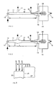
- a low frequency sound generator 10 is shown therein which can be of the positive feedback type described in US patent specification 4 359 962 of November 23, 1982. However, any other infrasound generator can be used for the purpose of the invention.
- the maximum frequency of the sound should be 150 Hz.
- the frequency is 40 Hz or lower. However, in most cases 20 Hz or lower (infrasound) is optimal.
- the sound generator 10 comprises a tubular resonator 11 closed at one end and open at the other end, the acoustic length of which, designated 1, is three quarter of the wave length of the sound emitted.
- the diameter of the resonator should be substantially less than said wave length.
- a feeder or drive unit 12, herein termed exigator for the purpose of this specification, is mounted at the closed end of the resonator and is connected to a supply conduit 13 for driving gas (air) supplied to and passing through the resonator under the control of the exigator as described in the US patent specification referred to above.
- the resonator is flared to form a diffusor 14 which connects to a space 15 forming a substantial enlargement in relation to the interior of the resonator.
- An inlet 16 to the space 15 is located opposite to the opening of the diffuser.
- An outlet 17 is provided in the resonance tube located in the resonator substantially in a region where the sound pressure of the standing wave in the resonator has a node, i.e. one third of the length of the resonator from the exigator.
- a conduit 18 extends radially into the resonator at a position between the ends thereof and then extends axially through the resonator towards the opening of the diffuser 14 to terminate close to the opening of the diffuser where the particle velocity of the standing wave of the sound has an antinode.
- the terminating end of the conduit is provided with a nozzle 19.
- the apparatus described is well suited for spray drying liquids, e.g. in the manufacture of instant products such as dry milk and instant coffee, and in connection with the supply of slurries of chemicals, e.g. a slurry of Ca(OH)2 and/or CaCO3 and water, for removal of SO2 or SO3 from flue gases by applying the method of the invention.
- slurries of chemicals e.g. a slurry of Ca(OH)2 and/or CaCO3 and water, for removal of SO2 or SO3 from flue gases by applying the method of the invention.
- gas such as hot air or hot flue gas is supplied to the space 15 through the inlet 16 and is passed to the outlet 17 through the resonator 11.
- the liquid to be processed in the case of the manufacture of an instant product or the slurry in the case of processing flue gas, is supplied to the nozzle 19 through the conduit 18 to be atomized and to enter the space 15 as a mist indicated at 20 which meets the gas entering through the inlet 16.
- the liquid phase of the atomized liquid or slurry in the mist will be evaporated when contacting the air or gas.
- an intimate mixture of the air and liquid or the flue gas and the slurry, respectively will be obtained intensifying the evaporation of the liquid or the liquid phase in the space 15 and particularly in the resonator tube 11.
- the air or gas including the evaporated liquid, with solid particles emanating from the liquid or slurry supplied entrained therein will pass through the resonator tube and will be discharged therefrom through the outlet 17.
- the nozzle 19 is located in the diffuser. It can as well be located in the space 15 or in the inlet 16 but notwithstanding the location thereof it should preferably be directed to supply the liquid or slurry in counterflow relation to the air or gas supplied through the inlet 16.
- a further increase in efficiency may in some cases be achieved by extending the length of the resonator 11 to five or seven quarters of the wave length of the sound. In principle any odd number of quarters of the wave length can be used.
- the resonator 11 forms an enlargement 21 at the outlet 17.
- the outlet In order to allow a large flow through the outlet as may be necessary in the practical application of the invention, it may be necessary to construct the outlet with a large diameter causing disturbance of the operation of the sound generator. In order to minimize such disturbance the enlargement is provided allowing the diameter of the outlet to be increased without adversely affecting the operation of the sound generator.
- FIG 2 is particularly well suited for the supply of pulverulent or gaseous fluids into the flue gas of boilers in regions where the temperature is high.
- pulverulent or gaseous fluids into the flue gas of boilers in regions where the temperature is high.
- the reaction between these compounds and SO2 and SO3 present in the flue gas is effected optimally at a temperature in the range of 1000 C.
- the compounds cannot simply be injected into a gas flow having a temperature in the said range due to the practical difficulties in obtaining a thorough mixture of the additives and the gas considering the high viscosity of the flue gas at high temperatures.
- the additives are supplied to the fluidized bed but in other cases the additives usually are supplied as a water slurry in a region where the flue gas temperature in the range of 200 C. At that temperature the reaction is slow and requires large equipment.
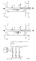
- the upper part of a utility boiler having a combustionchamber 22 is provided at the top thereof where the said region of 1000 C is located with a number of sound generators of the embodiment shown in FIG 2.
- the diffuser 14 of each generator is connected to the top wall of the boiler and communicates with the combustion chamber 22 thereof which thus forms space 15 shown i FIG 2.
- a wall 23 separates the combustion chamber 22 of the boiler from a convection area 24 thereof, otherwise communicating directly with the combustion chamber 22 in the absence of the wall 23.
- the outlet 17 of each sound generator is connected to the convection area 24.
- the additive e.g.
- CaCO3 in powder-form and NH3 in gas form is supplied through the conduit 18 of each sound generator to be dispersed in the flue gas by means of the nozzles 19. Under the influence of the low frequency sound the additives are thoroughly mixed with the flue gas in the resonator 11.
- each pair of sound generators preferably should be spaced at a distance from each other which is shorter than the distance to adjacent sound generators.
- the sound generator 10 shown in FIG 4 is of the half wave length type wherein the acoustic length l is half the wave length of the sound generated by the sound generator.
- the tubular resonator 11 in this case is open at both ends and the exigator 12 is located intermediate the ends at the longitudinal center of the resonator.
- the diffuser 14 at one end of the resonator is connected to a space 15 and the conduit 18 is extended into said diffuser for the supply of a fluid through the associated nozzle 19.
- a diffuser 14' is arranged which is connected to a space 15'.
- the sound pressure of the standing wave in the resonator has a node in each end region of the resonator.
- Additives are supplied to the gas passing through the resonator in the manner previously described.
- the diffuser 14 When this generator is used in connection with a utility boiler the diffuser 14 is connected to the combustion chamber 22 of the boiler as shown i FIG 6 and the diffuser 14' is connected to the convection area 24.
- the function of the embodiment shown i FIG 6 is the same as that described with reference to FIG 3.
- the resonator tube of the embodiment shown in FIG 4 can have a length which is a multiple of half the wave length with an exigator provided at one or more of the antinodes of the standing sound wave, i.e. where the sound pressure is at maximum.
- the exigators provided being operated synchronously.
- the driving gas supplied to the sound generator will cause a temperature fall of the flue gas passing through the resonator tube. This can be avoided in the case of using an exigator comprising two compartments, as shown in FIG 5, to which reference now is made.
- the driving gas is fed into one of the compartments through conduit 13 and sucked from the other through conduit 13', i.e. the driving gas does not cool the flue gas.
- One problem with the arrangement as shown i FIG 6 is that the length of the resonator tubes could substantially increase the total height of the boiler. In the case of a temperature of the flue gas of 1000 C, one half of the wave length of the sound is equal to about 17 meters at 20 Hz.
- the turbulence caused by the low frequency sound will only occur in the end regions of the half wave resonator. In the middle of the standing wave, the sound particle velocity has its minimum, i.e. the sound does not generate turbulence in this section.
- Another advantage of this arrangement is that the exigator 12 is placed at a point where the gas temperature is lower compared to the arrangement shown in FIG 4.
- This method of shortening the resonator tube could also be applied to the arrangement shown in FIG 1 and FIG 2.
- the nozzle 19 can be replaced by the arrangement shown in FIG 8 in cases where a liquid is supplied to a gas to be evaporated or to react with said gas or a substance contained therein.
- a body 26 of filler material allowing gas to pass through said body is supported in the resonator 11 below the opening of the conduit 18.
- the gas when passing through the filler body will be brought into contact with the liquid supplied to the body from the conduit 18.
- the contact between the liquid and the gas will be intensified under the influence of the low frequency sound.
Landscapes
- Chemical & Material Sciences (AREA)
- Engineering & Computer Science (AREA)
- Chemical Kinetics & Catalysis (AREA)
- Biomedical Technology (AREA)
- Environmental & Geological Engineering (AREA)
- Analytical Chemistry (AREA)
- General Chemical & Material Sciences (AREA)
- Oil, Petroleum & Natural Gas (AREA)
- Health & Medical Sciences (AREA)
- Physical Or Chemical Processes And Apparatus (AREA)
- Incineration Of Waste (AREA)
- Exhaust Silencers (AREA)
- Mixers With Rotating Receptacles And Mixers With Vibration Mechanisms (AREA)
- Gas Burners (AREA)
- Degasification And Air Bubble Elimination (AREA)
- Lasers (AREA)
- Steroid Compounds (AREA)
- Medicines Containing Plant Substances (AREA)
- Organic Low-Molecular-Weight Compounds And Preparation Thereof (AREA)
- Chemical Vapour Deposition (AREA)
- Treating Waste Gases (AREA)
Claims (15)
- Verfahren zur Erhöhung der Turbulenz in einem von Schall niederer Frequenz beaufschlagten Gas, der von einem Schallgenerator (10) mit einem rohrförmigen Resonator (11) mit offenem Ende (14) erzeugt wird, dadurch gekennzeichnet, daß der Schallgenerator bei einer der Resonanzfrequenzen des Resonators betrieben wird, und zwar bei einer maximalen Frequenz von 150 Hz, und daß das Gas in dem rohrförmigen Resonator durch das offene Ende einströmt und aus dem Resonator über einen Austritt (17) abströmt, der dort angeordnet ist, wo der Schalldruck der stehenden Welle im Resonator bei dieser Resonanzfrequenz des Resonators einen Knoten hat, nach dem wenigstens ein Teil der Länge des Resonators durchströmt worden ist.
- Verfahren nach Anspruch 1, dadurch gekennzeichnet, daß ein zweites Medium, das ein Pulver, eine Flüssigkeit, ein Gas oder eine Mischung davon enthält, dem Gas zur Vermischung unter dem Einfluß der erhöhten Turbulenz zugeführt wird.
- Verfahren nach Anspruch 1 oder 2, dadurch gekennzeichnet, daß das Gas in den rohrförmigen Resonator (11) aus einem Raum (15) zuströmen gelassen wird, der mit dem Resonator am offenen Ende (14) verbunden ist und eine wesentliche Vergrößerung gegenüber dem Inneren des Resonators bildet.
- Verfahren nach Anspruch 2, dadurch gekennzeichnet, daß das zweite Medium in Gegenstrom gegenüber dem Gas zugeführt wird.
- Verfahren nach den Ansprüchen 1 bis 4, dadurch gekennzeichnet, daß das zweite Medium nahe dem offenen Ende (14) des rohrförmigen Resonators (11) zugeführt wird.
- Verfahren nach Anspruch 1, dadurch gekennzeichnet, daß das Gas durch den rohrförmigen Resonator von dessen offenem Ende (14) zum anderen offenen Ende (14') durchströmt, wobei letzteres Ende einen Bereich bildet, wo der Schalldruck der stehenden Welle im Resonator bei dieser Resonanzfrequenz einen Knoten hat.
- Vorrichtung zur Erhöhung der Turbulenz in einem Gas durch das Verfahren gemäß einem der Ansprüche 1 bis 6 mit einem Schallgenerator (10) einschließlich eines rohrförmigen Resonators (11), der ein offenes Einlaßende (14) und Einrichtungen zum Zuführen des Gases zum Resonator an dessen offenem Ende hat, gekennzeichnet durch einen Austritt (17) am rohrförmigen Resonator zum Ausströmen des Gases aus dem rohrförmigen Resonator, wo der Schalldruck einen Knotenbereich bei der Resonanzfrequenz des Resonators hat und wobei der Austritt nach Innen vom Einlaßende des rohrförmigen Resonators einen Abstand hat.
- Vorrichtung nach Anspruch 7, dadurch gekennzeichnet, daß Einrichtungen (15) einen Raum begrenzen, der eine wesentliche Vergrößerung hinsichtlich des Innenteiles des rohrförmigen Resonators (11) am Austritt (17) bildet.
- Vorrichtung nach Anspruch 7, dadurch gekennzeichnet, daß der rohrförmige Resonator (11) ein Dreiviertelwellenresonator ist, der an einem Ende offen und am anderen Ende geschlossen ist.
- Vorrichtung nach Anspruch 9, dadurch gekennzeichnet, daß der Austritt (17) in einem Abstand vom offenen Einlaßende (14) des Resonators angeordnet ist, der im wesentlichen gleich einer halben Wellenlänge bei dieser Resonanzfrequenz ist.
- Vorrichtung nach Anspruch 10, dadurch gekennzeichnet, daß der rohrförmige Resonator (11) eine Vergrößerung (21) am Austritt (17) bildet.
- Vorrichtung nach Anspruch 7, dadurch gekennzeichnet, daß der rohrförmige Resonator (11) ein Halbwellen-Resonator ist, der an beiden Enden (14, 14') zum Durchtritt des Gases durch den Resonator von einem Ende zum anderen offen ist.
- Vorrichtung nach Anspruch 12, dadurch gekennzeichnet, daß der rohrförmige Resonator (11) an jedem offenen Ende (14, 14') einen Diffusor bildet.
- Vorrichtung nach Anspruch 12, dadurch gekennzeichnet, daß der Schallgenerator (10) vom pneumatischen Typ ist und durch abwechselndes Zuführen und Absaugen von Luft zur bzw. von der Antriebseinheit (12) betrieben wird.
- Vorrichtung nach Anspruch 12, dadurch gekennzeichnet, daß der Resonator (11) ein T-förmiger Resonator ist, dessen Querabschnitt einen Durchtritt für das Gas und dessen senkrechter Schenkel eine Querschnittsfläche hat, die im wesentlichen das Doppelte der Querschnittsfläche des Querabschnittes ist, wobei die Antriebseinheit (12) des Schallgenerators mit dem geschlossenen Ende des senkrechten Schenkels verbunden ist.
Priority Applications (1)
| Application Number | Priority Date | Filing Date | Title |
|---|---|---|---|
| AT86900880T ATE68720T1 (de) | 1985-01-22 | 1986-01-22 | Verfahren und vorrichtung zur erhoehung der turbulenz in einem vom gas beanschlagten schall niedriger frequenz. |
Applications Claiming Priority (2)
| Application Number | Priority Date | Filing Date | Title |
|---|---|---|---|
| SE8500276A SE8500276D0 (sv) | 1985-01-22 | 1985-01-22 | Method of mixing fluids and apparatus for working the method |
| SE8500276 | 1985-01-22 |
Publications (2)
| Publication Number | Publication Date |
|---|---|
| EP0211034A1 EP0211034A1 (de) | 1987-02-25 |
| EP0211034B1 true EP0211034B1 (de) | 1991-10-23 |
Family
ID=20358845
Family Applications (1)
| Application Number | Title | Priority Date | Filing Date |
|---|---|---|---|
| EP86900880A Expired - Lifetime EP0211034B1 (de) | 1985-01-22 | 1986-01-22 | Verfahren und vorrichtung zur erhöhung der turbulenz in einem vom gas beanschlagten schall niedriger frequenz |
Country Status (13)
| Country | Link |
|---|---|
| US (1) | US4721395A (de) |
| EP (1) | EP0211034B1 (de) |
| JP (1) | JPS62501756A (de) |
| KR (1) | KR930008627B1 (de) |
| AT (1) | ATE68720T1 (de) |
| AU (1) | AU585580B2 (de) |
| BR (1) | BR8604735A (de) |
| DE (1) | DE3682138D1 (de) |
| DK (1) | DK452086D0 (de) |
| FI (1) | FI84788C (de) |
| NO (1) | NO863750L (de) |
| SE (1) | SE8500276D0 (de) |
| WO (1) | WO1986004263A1 (de) |
Families Citing this family (9)
| Publication number | Priority date | Publication date | Assignee | Title |
|---|---|---|---|---|
| US5595585A (en) * | 1994-05-02 | 1997-01-21 | Owens Corning Fiberglas Technology, Inc. | Low frequency sound distribution of rotary fiberizer veils |
| BE1010628A3 (nl) * | 1996-09-17 | 1998-11-03 | Verbandt Filip Julien Romain | Werkwijze voor het verbeteren van de werking van een katalysator en katalytische reactor met verbeterde werking. |
| DE10016154C2 (de) * | 2000-03-27 | 2002-04-18 | Amr Diagnostics Ag | Verfahren und Anordnung zum Eintrag von Substanzen oder Substanzgemischen in Gase oder Flüssigkeiten |
| US7056366B2 (en) * | 2002-06-17 | 2006-06-06 | Technion Research And Development Foundation, Ltd | Method and apparatus for increasing the operating lifetime of gas filters by an acoustic field |
| US7318374B2 (en) * | 2003-01-21 | 2008-01-15 | Victor Guerrero | Wire cloth coffee filtering systems |
| US7461587B2 (en) * | 2004-01-21 | 2008-12-09 | Victor Guerrero | Beverage container with wire cloth filter |
| JP5115929B2 (ja) * | 2008-06-20 | 2013-01-09 | 寛一 伊藤 | 液状物質の処理装置 |
| US20160236136A1 (en) * | 2015-02-12 | 2016-08-18 | Clyde Bergemann Power Group Americas Inc. | Apparatus and method of using sound waves to reduce sorbent consumption in dry sorbent injection air pollution control systems |
| JP2023510699A (ja) * | 2019-12-20 | 2023-03-15 | オートテック エンジニアリング エス.エレ. | 物体を成形するための方法及び製造ライン |
Family Cites Families (8)
| Publication number | Priority date | Publication date | Assignee | Title |
|---|---|---|---|---|
| DE908487C (de) * | 1941-02-27 | 1954-04-05 | Siemens Ag | Anordnung zur Gasanreicherung von Fluessigkeiten |
| US3109721A (en) * | 1958-11-21 | 1963-11-05 | Union Carbide Corp | Method and apparatus for separating a fluid mixture by sonic energy |
| US3259272A (en) * | 1964-06-19 | 1966-07-05 | Korad Corp | Method and apparatus for dispensing powder |
| US3467363A (en) * | 1967-08-31 | 1969-09-16 | Richard Alan Reichel | Noise generator for shaking loose packed material |
| DE1917962A1 (de) * | 1969-04-09 | 1971-02-25 | Maschf Augsburg Nuernberg Ag | Schalldruckpumpen |
| EP0006833B1 (de) * | 1978-07-03 | 1983-09-14 | Mats Olsson Konsult Ab | Niederfrequenz Schallgeber |
| EP0098949B1 (de) * | 1982-07-01 | 1986-11-05 | Eppendorf Gerätebau Netheler + Hinz GmbH | Verfahren zur Mischung von zu analysierenden Flüssigkeitsproben |
| SE458799B (sv) * | 1983-12-02 | 1989-05-08 | Insako Ab | Saett och anordning foer foerbraenning av fluida braenslen |
-
1985
- 1985-01-22 SE SE8500276A patent/SE8500276D0/xx unknown
-
1986
- 1986-01-22 KR KR1019860700653A patent/KR930008627B1/ko not_active Expired - Fee Related
- 1986-01-22 JP JP61500842A patent/JPS62501756A/ja active Pending
- 1986-01-22 WO PCT/SE1986/000019 patent/WO1986004263A1/en not_active Ceased
- 1986-01-22 BR BR8604735A patent/BR8604735A/pt unknown
- 1986-01-22 US US06/916,543 patent/US4721395A/en not_active Expired - Fee Related
- 1986-01-22 DE DE8686900880T patent/DE3682138D1/de not_active Expired - Lifetime
- 1986-01-22 EP EP86900880A patent/EP0211034B1/de not_active Expired - Lifetime
- 1986-01-22 AT AT86900880T patent/ATE68720T1/de not_active IP Right Cessation
- 1986-01-22 AU AU53194/86A patent/AU585580B2/en not_active Ceased
- 1986-09-19 NO NO863750A patent/NO863750L/no unknown
- 1986-09-19 FI FI863787A patent/FI84788C/fi not_active IP Right Cessation
- 1986-09-22 DK DK452086A patent/DK452086D0/da not_active Application Discontinuation
Also Published As
| Publication number | Publication date |
|---|---|
| EP0211034A1 (de) | 1987-02-25 |
| DK452086A (da) | 1986-09-22 |
| SE8500276D0 (sv) | 1985-01-22 |
| KR930008627B1 (ko) | 1993-09-11 |
| DK452086D0 (da) | 1986-09-22 |
| AU5319486A (en) | 1986-08-13 |
| FI84788B (fi) | 1991-10-15 |
| DE3682138D1 (de) | 1991-11-28 |
| JPS62501756A (ja) | 1987-07-16 |
| US4721395A (en) | 1988-01-26 |
| WO1986004263A1 (en) | 1986-07-31 |
| NO863750D0 (no) | 1986-09-19 |
| FI863787L (fi) | 1986-09-19 |
| NO863750L (no) | 1986-09-19 |
| KR870700400A (ko) | 1987-12-29 |
| FI84788C (fi) | 1992-01-27 |
| BR8604735A (pt) | 1987-08-04 |
| FI863787A0 (fi) | 1986-09-19 |
| AU585580B2 (en) | 1989-06-22 |
| ATE68720T1 (de) | 1991-11-15 |
Similar Documents
| Publication | Publication Date | Title |
|---|---|---|
| EP0211034B1 (de) | Verfahren und vorrichtung zur erhöhung der turbulenz in einem vom gas beanschlagten schall niedriger frequenz | |
| EP0861408B1 (de) | Verfahren und vorrichtung zum trocknen und heizen | |
| US4741624A (en) | Device for putting in contact fluids appearing in the form of different phases | |
| US5015171A (en) | Tunable pulse combustor | |
| US4909731A (en) | Method and apparatus for conducting a process in a pulsating environment | |
| US3904376A (en) | Apparatus for cleaning the discharge of a smokestack or the like | |
| US5168835A (en) | Pulsating combustion device | |
| RU1816231C (ru) | Устройство теплообмена между твердыми частицами и теплообменной средой | |
| CA2554983C (en) | Swinging agitator for a gypsum calcining apparatus and the like | |
| US7121713B2 (en) | Swinging agitator for a gypsum calcining apparatus and the like | |
| US3976453A (en) | Liquid vortex vacuum pump | |
| JP2587231B2 (ja) | 炭化水素材料の流体の接触分解用装置 | |
| US3669630A (en) | Apparatus for thermocatalytic neutralizing of exhaust gases of an internal combustion engine | |
| CA1178880A (en) | Resonant chamber atomizer for liquids | |
| US7434980B2 (en) | Swinging agitator for a gypsum calcining apparatus and the like | |
| US4044099A (en) | Polluted air effluent incinerating method | |
| SU951034A1 (ru) | Распылительна сушилка | |
| SU1530239A1 (ru) | Реактор дл получени фосфорной кислоты | |
| EP0529988A1 (de) | Vorrichtung mit pulsierender Verbrennung | |
| US3694924A (en) | Apparatus for drying particulate solids | |
| SU1481572A1 (ru) | Распылительна сушилка | |
| SU1281813A1 (ru) | Паровод ной подогреватель | |
| SU559723A1 (ru) | Устройство дл термокаталитической очистки отход щих газов | |
| JPS6230826B2 (de) | ||
| SU967525A1 (ru) | Скруббер |
Legal Events
| Date | Code | Title | Description |
|---|---|---|---|
| PUAI | Public reference made under article 153(3) epc to a published international application that has entered the european phase |
Free format text: ORIGINAL CODE: 0009012 |
|
| 17P | Request for examination filed |
Effective date: 19861009 |
|
| AK | Designated contracting states |
Kind code of ref document: A1 Designated state(s): AT BE CH DE FR GB IT LI NL SE |
|
| 17Q | First examination report despatched |
Effective date: 19871209 |
|
| RAP1 | Party data changed (applicant data changed or rights of an application transferred) |
Owner name: INFRASONIK AB |
|
| RAP1 | Party data changed (applicant data changed or rights of an application transferred) |
Owner name: INFRASONIK AB |
|
| GRAA | (expected) grant |
Free format text: ORIGINAL CODE: 0009210 |
|
| AK | Designated contracting states |
Kind code of ref document: B1 Designated state(s): AT BE CH DE FR GB IT LI NL SE |
|
| PG25 | Lapsed in a contracting state [announced via postgrant information from national office to epo] |
Ref country code: IT Free format text: LAPSE BECAUSE OF FAILURE TO SUBMIT A TRANSLATION OF THE DESCRIPTION OR TO PAY THE FEE WITHIN THE PRE;WARNING: LAPSES OF ITALIAN PATENTS WITH EFFECTIVE DATE BEFORE 2007 MAY HAVE OCCURRED AT ANY TIME BEFORE 2007. THE CORRECT EFFECTIVE DATE MAY BE DIFFERENT FROM THE ONE RECORDED.SCRIBED TIME-LIMIT Effective date: 19911023 Ref country code: AT Effective date: 19911023 Ref country code: CH Effective date: 19911023 Ref country code: LI Effective date: 19911023 Ref country code: NL Effective date: 19911023 Ref country code: SE Effective date: 19911023 |
|
| REF | Corresponds to: |
Ref document number: 68720 Country of ref document: AT Date of ref document: 19911115 Kind code of ref document: T |
|
| REF | Corresponds to: |
Ref document number: 3682138 Country of ref document: DE Date of ref document: 19911128 |
|
| PGFP | Annual fee paid to national office [announced via postgrant information from national office to epo] |
Ref country code: FR Payment date: 19920113 Year of fee payment: 7 |
|
| PGFP | Annual fee paid to national office [announced via postgrant information from national office to epo] |
Ref country code: GB Payment date: 19920123 Year of fee payment: 7 |
|
| PGFP | Annual fee paid to national office [announced via postgrant information from national office to epo] |
Ref country code: DE Payment date: 19920124 Year of fee payment: 7 |
|
| PG25 | Lapsed in a contracting state [announced via postgrant information from national office to epo] |
Ref country code: BE Effective date: 19920131 |
|
| REG | Reference to a national code |
Ref country code: CH Ref legal event code: PL |
|
| ET | Fr: translation filed | ||
| NLV1 | Nl: lapsed or annulled due to failure to fulfill the requirements of art. 29p and 29m of the patents act | ||
| BERE | Be: lapsed |
Owner name: INFRASONIK A.B. Effective date: 19920131 |
|
| PLBE | No opposition filed within time limit |
Free format text: ORIGINAL CODE: 0009261 |
|
| STAA | Information on the status of an ep patent application or granted ep patent |
Free format text: STATUS: NO OPPOSITION FILED WITHIN TIME LIMIT |
|
| 26N | No opposition filed | ||
| PG25 | Lapsed in a contracting state [announced via postgrant information from national office to epo] |
Ref country code: GB Effective date: 19930122 |
|
| GBPC | Gb: european patent ceased through non-payment of renewal fee |
Effective date: 19930122 |
|
| PG25 | Lapsed in a contracting state [announced via postgrant information from national office to epo] |
Ref country code: FR Effective date: 19930930 |
|
| PG25 | Lapsed in a contracting state [announced via postgrant information from national office to epo] |
Ref country code: DE Effective date: 19931001 |
|
| REG | Reference to a national code |
Ref country code: FR Ref legal event code: ST |