EP0210920B1 - Einrichtung für den kathodischen Schutz einer Anlage mittels aufgedrückten Stromes - Google Patents
Einrichtung für den kathodischen Schutz einer Anlage mittels aufgedrückten Stromes Download PDFInfo
- Publication number
- EP0210920B1 EP0210920B1 EP86401638A EP86401638A EP0210920B1 EP 0210920 B1 EP0210920 B1 EP 0210920B1 EP 86401638 A EP86401638 A EP 86401638A EP 86401638 A EP86401638 A EP 86401638A EP 0210920 B1 EP0210920 B1 EP 0210920B1
- Authority
- EP
- European Patent Office
- Prior art keywords
- anodes
- generator
- potential
- electrolyte
- protected
- Prior art date
- Legal status (The legal status is an assumption and is not a legal conclusion. Google has not performed a legal analysis and makes no representation as to the accuracy of the status listed.)
- Expired
Links
Images
Classifications
-
- C—CHEMISTRY; METALLURGY
- C25—ELECTROLYTIC OR ELECTROPHORETIC PROCESSES; APPARATUS THEREFOR
- C25D—PROCESSES FOR THE ELECTROLYTIC OR ELECTROPHORETIC PRODUCTION OF COATINGS; ELECTROFORMING; APPARATUS THEREFOR
- C25D21/00—Processes for servicing or operating cells for electrolytic coating
- C25D21/12—Process control or regulation
-
- C—CHEMISTRY; METALLURGY
- C23—COATING METALLIC MATERIAL; COATING MATERIAL WITH METALLIC MATERIAL; CHEMICAL SURFACE TREATMENT; DIFFUSION TREATMENT OF METALLIC MATERIAL; COATING BY VACUUM EVAPORATION, BY SPUTTERING, BY ION IMPLANTATION OR BY CHEMICAL VAPOUR DEPOSITION, IN GENERAL; INHIBITING CORROSION OF METALLIC MATERIAL OR INCRUSTATION IN GENERAL
- C23F—NON-MECHANICAL REMOVAL OF METALLIC MATERIAL FROM SURFACE; INHIBITING CORROSION OF METALLIC MATERIAL OR INCRUSTATION IN GENERAL; MULTI-STEP PROCESSES FOR SURFACE TREATMENT OF METALLIC MATERIAL INVOLVING AT LEAST ONE PROCESS PROVIDED FOR IN CLASS C23 AND AT LEAST ONE PROCESS COVERED BY SUBCLASS C21D OR C22F OR CLASS C25
- C23F13/00—Inhibiting corrosion of metals by anodic or cathodic protection
- C23F13/02—Inhibiting corrosion of metals by anodic or cathodic protection cathodic; Selection of conditions, parameters or procedures for cathodic protection, e.g. of electrical conditions
- C23F13/04—Controlling or regulating desired parameters
-
- G—PHYSICS
- G01—MEASURING; TESTING
- G01R—MEASURING ELECTRIC VARIABLES; MEASURING MAGNETIC VARIABLES
- G01R17/00—Measuring arrangements involving comparison with a reference value, e.g. bridge
- G01R17/02—Arrangements in which the value to be measured is automatically compared with a reference value
Definitions
- the subject of the present invention is a device for cathodic protection of a structure by applied current, comprising at least one cathode constituted by the structure to be protected, at least one group of anodes isolated from the structure and in contact with the electrolyte in which is placed said structure, at least one direct current generator connected between the cathode structure and the anodes of said group in contact with the electrolyte and at least one reference electrode connected to a command and regulation circuit for adjusting the voltage delivered by said generator and thereby the current applied to said anodes.
- Cathodic protection is a means of protection against corrosion of buried and submerged metal structures. It is obtained by causing a direct current generator to flow between anodes placed in the electrolyte (water or soil) and isolated from the structure, and a cathode formed by the structure to be protected.
- the polarization conditions of the metals to be protected vary according to a large number of factors: variation in the insulation resistance of the coating if it exists, variation in the resistivity of the electrolyte, influence of the speed of the electrolyte, formation of deposits on protected parts etc ...
- the characteristics of the DC generator must therefore be adapted so that the polarization is maintained at a suitable value.
- the power level of the generator is often adjusted manually.
- the value of the output voltage is then varied for example using a variable annular auto-transformer, a transformer with magnetic saturation, a transformer with multiple taps, or devices with thyristors or triacs .
- the generator power level can also be adjusted automatically by means of a servo control.
- the servo-control ensures on the one hand the comparison between a setpoint potential to be imposed and the potential of the structure to be protected measured with a reference electrode permanently placed on this structure to deliver a control signal, and on the other hand, the amplification of this signal and its transformation into current applied between the anodes and the structure to be protected in a direction such that this current tends to bring the potential of this structure to the value of the setpoint potential.
- Such a device is commonly called a "potentiostat”.
- the potentiostat must be oversized to ensure its function whatever the polarization conditions.
- the present invention aims precisely to remedy the aforementioned drawbacks and to allow the automatic adaptation of a cathodic protection current generator to variations in the polarization conditions without the need to oversize the system and while reducing the influence of interference on the potential of the structure to be protected which is due to the presence of an electrolyte common to different anode-cathode circuits.
- the invention also aims to provide a system which can also be applied to at least two separate cathodes polarized by at least one generator and one anode each, whose electric fields of the anode-rectifier-cathode assemblies interfere.
- a cathodic protection device of an applied current structure of the type mentioned at the head of the description which, according to the invention, includes means for cyclically putting the control circuit into operation and for regulating a generator, means for reading the potential supplied by the reference electrode and for calculating the potential difference between the protected structure and the potential for the electrode read, means for comparing the calculated potential difference on the one hand with a first reference potential constituting a high threshold and on the other hand with a second reference potential constituting a low threshold, and means for adjusting by step of a predetermined value the absolute value of the output voltage delivered by the generator in the direction of an increase if the calculated potential difference is less negative than that of the high threshold or in the direction of a reduction if the calculated potential difference is more negative than that of the low threshold.
- the means for cyclically commissioning the control and regulation circuit of a generator comprise a clock, the frequency of the cycles of which is adapted to the duration of the electrochemical polarization.
- the means for cyclically commissioning the control and regulation circuit of a generator comprise a timed contact whose closure is linked to the operation of the structure to be protected.
- a generator control and regulation circuit can thus be cyclically controlled using a relay controlled by the state of the machine comprising the structure to be protected.
- the device comprises at least two reference electrodes connected to the command and regulation circuit associated with the same generator and the same group of anodes and the reference potential reading means comprise a comparator circuit for determining at each cycle the most electro-negative reference electrode and choose the most negative potential for the calculation of the calculated potential difference.
- the device further comprises signaling means when the difference between the potentials of the reference electrodes exceeds a predetermined value.
- the device comprises several groups of anodes distributed in various zones of the structure to be protected, isolated from the latter and in contact with the electrolyte; direct current generators in number p equal to the number p of anode groups, each generator being connected to a group of anodes; groups of reference electrodes arranged in the vicinity of the different anode groups and connected to the different control and regulation circuits to adjust the voltage delivered by each of the generators associated with the different anode groups; means for cyclically putting into service the different control and regulation circuits and means for assigning to each control and regulation circuit first and second reference potentials constituting high and low thresholds and for adjusting in steps of a predetermined value the value of the output voltage delivered by each generator associated with a group of anodes as a function of the value of the potential difference calculated with respect to the high and low thresholds.
- the reference electrodes are constituted by electrodes comprising a reservoir of a saturated electrolyte so as to have properties maintained constant over time whatever the variations in the composition of the electrolyte in which the structure to be protected is placed. .
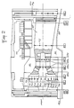
- a metal structure capable of playing the role of cathode and can thus be the subject of cathodic protection is, for example, a turbine 60 known as "running over water” placed in an aqueous medium 90 which may be a marine environment and surrounded by an infrastructure 80.
- the invention is however applicable to many other types of metal structures that can be submerged or buried, for example alternators, metal pipes, valves or ship hulls.
- FIG. 2 only shows the overall power supplies 70 of the various groups of anodes.
- the anodes An, A 12 , A 13 , A 14 of group A and the anodes A 2 ,, A 22 , A 23 , A 24 , A 25 , A 26 , A 27 , A 28 of group A 2 .
- Each anode A ij is isolated from the metal structure 60 which itself plays the role of cathode and is in contact with the electrolyte 90.
- the anodes A ij can be placed in relief on the metal structure 60, with interposition of an insulating element between the structure 60 and each anode A ij .
- the anodes A ij can also be embedded and then be placed not directly on the metal structure 60 but in the concrete of the civil engineering of the structure to be protected. Such anodes are then each made up of a metal part embedded in a plastic sole and provided with a sealed connection, the assembly being placed in a housing provided for this purpose.
- the anodes A ij of a group A are placed so as to ensure a good distribution of the electric field within the electrolyte 90.
- the different groups of anodes A 1 to A 10 correspond to different parts of the machine to be protected, for example to different sub-assemblies of the metallic structure of a turbo alternator group as shown in the figure 2.
- a group of at least two reference electrodes is arranged in the vicinity of each group of anodes.
- the pairs of reference electrodes associated with the groups of anodes A 1 to 2 have been identified in FIG. 2 by the references ER1 to ER10. A 10 respectively.
- the potential of the reference electrodes is not stable because it depends on the concentration of the ion reacting in the process of forming the electrode potential (by example the chlorine ion for the Mercury / Calomel electrodes or those with Silver / Silver chloride).
- reference electrodes can be used fitted with a reservoir filled with reacting salt crystals which saturate the solution in which the electrode is bathed. Since the connection between the saturated solution and the external medium takes place through a porous filter, the period during which the electrode gives a stable indication depends on the diffusion rate of the porous filter and on the salt capacity of the electrode reservoir . However, it is possible by this means to manufacture electrodes whose operation is guaranteed for more than a year.
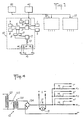
- FIG. 1 schematically shows a set of control and regulation circuits 10, 20, 30 .... which can be used in combination with the anode groups A i , A 2 , A 3 ,. .. and the sets of reference electrodes ER1, ER2, ER3, ... in Figure 2.
- a direct current is made to circulate between anodes immersed in the ground or the liquid surrounding the metallic structure to be protected and said structure which constitutes a cathode. It is important to maintain the value of the current used within a given range of values. Indeed, too low a current value is not able to prevent corrosion from continuing while too high current leads to a waste of electrical energy.
- the reference electrodes allow precisely, by measuring the potential difference existing between them whose potential is assumed to be stable and the structure to be protected whose potential is variable, to monitor whether the applied current is correct, too high or too low.
- the signals from the reference electrodes are amplified and are used to actuate devices which modify the direct applied current coming from a generator in order to permanently maintain the applied current within a predetermined range of values.
- the use of a low time constant servo ensuring the constancy of the potential of the structure to be protected at a value equal to or less than the maximum cathodic protection potential leads to installing a generator oversized current to meet the maximum current demand, since the current demand varies considerably with the speed of the electrolyte in contact with the metal to be protected, which speed is not negligible when it is for example of a structure in rough seawater, and the fact that the formation of calcium deposits on the structure to be protected is difficult to control.
- a continuous control furthermore causes oscillations of the current delivered by the generators.
- each control and regulation circuit 10, 20, 30 according to the invention is controlled cyclically in order to adapt the current in steps during use so as to bring the potential of the device in stages. structure to be protected within a range of predetermined values.
- the control circuit 10 associated with the first group of anodes A 1 and with the set ER1 of reference electrodes 1,2 placed on the part of the machine to be protected concerned by the generator 12 delivering a current will be described below. at the anodes A 11 to A 1n of group A ,.
- the reference electrodes 1 and 2 are connected to a comparator 3 which measures the potential difference between the electrodes 1, 2 and selects the most electro-negative electrode 1 or 2 for controlling the regulation.
- a single reference electrode 1 or 2 is thus used for controlling the regulation, but the second reference electrode makes it possible to carry out each time a check of the reference electrodes 1, 2 using the comparator 3.
- the potential difference measured by the comparator 3 exceeds a predetermined threshold set by the threshold circuit 4 connected to the comparator 3, an alarm 5 is triggered to indicate that at least one of the reference electrodes 1,2 is deficient.
- the potential of the reference electrode 1 or 2 selected by the comparator 3 is applied to a second comparator 6 which performs a double comparison between on the one hand the potential provided by the comparator 3 and on the other hand potentials of value E H and E B constituting high and low thresholds and generated by circuits 7 and 8 connected to comparator 6.
- the high and low thresholds E H and E B are generated by means of a reference voltage if a comparator is used analog 6 or stored in memories if comparator 6 is of digital type.
- the comparator 6 does not deliver any signal to the relays 9 or 11 responsible for controlling the variation of the output voltage of the generator 12. If the. value provided by comparator 3 is more negative than that of low threshold E s , the polarization is excessive and a signal of a fixed duration is applied to relay 11 which commands a reduction of a value fixed in advance (for example 0.2v) of the voltage delivered by the generator 12.
- the relay 9 commands an increase of predetermined fixed value (for example also of 0.2v) of the voltage delivered by the generator 12.
- Each cycle as described above is initiated either by a clock 40 the frequency of the cycles of which is adapted to the duration of the electrochemical polarization (this frequency possibly being for example two cycles per day), or by a timed contact 50 in relationship with the functioning of the organ 60 to be protected.
- the timed contact 50 can thus be triggered each time the machine is started.
- a direct current generator 12 can for example comprise a variable auto-transformer 121 supplying via a transformer 123 a rectifier circuit 124 which is itself connected to a group of anodes A i .
- the current I delivered by the rectifier circuit 124 is measured using a shunt 13 at the terminals of which an ammeter 15 is connected.
- the transformation ratio of the auto-transformer 121 can be controlled by an electro-mechanical system with a motor 122 or electronically from a micro-computer managing the control circuit 10 so as to be able to impose a current fixed by the micro -computer from the information provided by comparison steps 3 and 6.
- Resistors 14 connected in series between the generator 12 and the anodes A 11 to A 1n respectively make it possible to take signals representative of the current applied to each anode A 11 to A 1n of the same group A, from the generator 12.
- An overcurrent limiting device can be associated with the control circuit 10.
- the value of the maximum current to be supplied by the rectifier 124 being stored, a comparison between the maximum current value memorized and the value supplied by the ammeter 15 or the measuring devices connected to the terminals of the resistors 14 is carried out at each current readjustment cycle during the control of the variation of the variable auto-transformer 121.
- This comparison results in an order to stop the movement of the cursor of the auto -transformer 121 or a reverse movement whose action limits or reduces the voltage applied by the rectifier 124 to a value such that during a step change of the value of the current delivered by the generator 12 the current does not exceed the threshold predetermined overcurrent limitation.
- An essential interest of the control system according to the invention lies in the step-by-step adjustment made over time of the characteristics of the rectifiers to variations in the cathodic polarization conditions, the safety of the system being ensured by the choice of an electrode for reference among several 1.2 located in the vicinity of one another.
- This step-by-step adjustment eliminates the need for manual control and adjustment. Furthermore, the cyclic action makes it possible to intervene on several cathodic protection generators controlling groups of anodes A, to A, o capable of influencing each other.
- control circuits 10, 20, 30 ... associated with the different groups of anodes A 1 , A 2 , A 3 .... It is possible to reduce the interference of the different circuits between them on the potential of the structure to be protected.
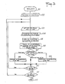
- FIG. 3 shows a simplified flowchart showing the functional diagram of the regulation of a cathodic protection device according to the invention using several groups A of anodes A ij .
- Step 101 corresponds to the initialization of the regulation.
- Step 102 defines a polling frequency which conditions the cyclic behavior and must be adapted to the operating conditions.
- This scanning frequency corresponds to the frequency of the clock 40 in FIG. 1 and can be of the order of one or two cycles per day.
- the initialization of the regulation can however also be controlled by the time relay 50 actuated for example when the machine is started or when a particular operation is carried out, such as for example a pumping operation, which ensures that the current adjustment sequence will always be carried out under similar polarization conditions.
- the regulation scheme includes a series of polling loops, the number of which depends on the polling frequency, with a test 111 of end of polling loop which determines the end 112 of a regulation cycle.
- one or more group loops are performed depending on whether the cathodic protection device comprises one or more groups of anodes.
- step 103 corresponds to the reading of the high and low thresholds EH i and EB i which define a range of potential adapted to the particular depolarization conditions in the vicinity of group d 'electrodes considered.
- step 104 corresponds to the acquisition of the pairs of electrode potentials ELi1 and ELi2 corresponding to the two reference electrodes 1, 2 associated with the control circuit of the group considered A.
- Step 105 of a group loop corresponds to the choice of the electrode 1 or 2 with the lowest potential by comparison of the potential values of reference electrodes ELi1 and ELi2.
- the optional step of comparing the absolute value of the difference ELi1-ELi2 to a determined threshold and to trigger an alarm if this threshold is exceeded (circuits 4 and 5 in Figure 1).
- Step 106 of a group loop corresponds to the calculation of the potential difference between the structure to be protected 60 and the potential of the reference electrode used in step 105.
- Step 107 consists of a double test with a comparison of the value calculated in step 106 with on the one hand the high threshold EHi and on the other hand the low threshold EBi read in step 103. If the value of calculated potential difference is greater than the high threshold EHi, the next step is step 108 consisting in decreasing by one step the value of the current delivered by the current generator 12 of the loop considered.
- step 109 consisting in increasing by one step the value of the current delivered by the current generator 12 of the loop considered.
Landscapes
- Chemical & Material Sciences (AREA)
- Engineering & Computer Science (AREA)
- Materials Engineering (AREA)
- Metallurgy (AREA)
- Organic Chemistry (AREA)
- Mechanical Engineering (AREA)
- Physics & Mathematics (AREA)
- General Physics & Mathematics (AREA)
- Automation & Control Theory (AREA)
- Chemical Kinetics & Catalysis (AREA)
- Electrochemistry (AREA)
- Prevention Of Electric Corrosion (AREA)
Claims (8)
Priority Applications (2)
| Application Number | Priority Date | Filing Date | Title |
|---|---|---|---|
| IN650/DEL/86A IN168063B (de) | 1985-07-23 | 1986-07-21 | |
| AT86401638T ATE42579T1 (de) | 1985-07-23 | 1986-07-22 | Einrichtung fuer den kathodischen schutz einer anlage mittels aufgedrueckten stromes. |
Applications Claiming Priority (2)
| Application Number | Priority Date | Filing Date | Title |
|---|---|---|---|
| FR8511259A FR2589486B1 (fr) | 1985-07-23 | 1985-07-23 | Dispositif de protection cathodique d'une structure par courant applique |
| FR8511259 | 1985-07-23 |
Publications (2)
| Publication Number | Publication Date |
|---|---|
| EP0210920A1 EP0210920A1 (de) | 1987-02-04 |
| EP0210920B1 true EP0210920B1 (de) | 1989-04-26 |
Family
ID=9321556
Family Applications (1)
| Application Number | Title | Priority Date | Filing Date |
|---|---|---|---|
| EP86401638A Expired EP0210920B1 (de) | 1985-07-23 | 1986-07-22 | Einrichtung für den kathodischen Schutz einer Anlage mittels aufgedrückten Stromes |
Country Status (9)
| Country | Link |
|---|---|
| US (1) | US4713158A (de) |
| EP (1) | EP0210920B1 (de) |
| KR (1) | KR870001335A (de) |
| CN (1) | CN86105112A (de) |
| AU (1) | AU582979B2 (de) |
| CA (1) | CA1282368C (de) |
| DE (1) | DE3663040D1 (de) |
| FR (1) | FR2589486B1 (de) |
| NZ (1) | NZ216935A (de) |
Families Citing this family (29)
| Publication number | Priority date | Publication date | Assignee | Title |
|---|---|---|---|---|
| DE4025088A1 (de) * | 1990-08-08 | 1992-02-13 | Vaw Ver Aluminium Werke Ag | Kathodischer korrosionsschutz fuer ein aluminium enthaltendes substrat |
| ES2042415B1 (es) * | 1992-05-07 | 1997-02-01 | W W I Proytec S L | Sistema de proteccion catodica por corriente impresa para partes metalicas de embarcaciones. |
| RU2149220C1 (ru) * | 1997-11-11 | 2000-05-20 | Центральный научно-исследовательский институт конструкционных материалов "Прометей" | Устройство для питания и автоматического регулирования выходного тока системы катодной защиты от коррозии металлоконструкций |
| FI119150B (fi) | 1999-05-17 | 2008-08-15 | Savcor Process Oy | Menetelmä sähkökemiallisen korroosioneston toteuttamiseksi muuttuvissa olosuhteissa |
| RU2204168C2 (ru) * | 1999-09-13 | 2003-05-10 | ОАО "Газпром" | Устройство дистанционного контроля работоспособности установок катодной защиты магистральных трубопроводов |
| RU2202001C2 (ru) * | 1999-09-13 | 2003-04-10 | ОАО "Газпром" | Система катодной защиты магистральных трубопроводов |
| US6183625B1 (en) * | 1999-11-08 | 2001-02-06 | Brunswick Corporation | Marine galvanic protection monitor |
| RU2157424C1 (ru) * | 2000-01-31 | 2000-10-10 | Южно-Уральский государственный университет | Система катодной защиты и диагностики трубопровода |
| RU2161663C1 (ru) * | 2000-04-11 | 2001-01-10 | Открытое акционерное общество "НЕФТЕГАЗПРОЕКТ" | Система катодной защиты магистральных трубопроводов от коррозии |
| US7064459B1 (en) * | 2001-08-20 | 2006-06-20 | Brunswick Corporation | Method of inhibiting corrosion of a component of a marine vessel |
| RU2233912C1 (ru) * | 2003-10-01 | 2004-08-10 | Открытое акционерное общество "Татнефть" им. В.Д. Шашина | Способ защиты от коррозии трубопроводов, транспортирующих нефть с высокой обводненностью |
| US7189319B2 (en) * | 2004-02-18 | 2007-03-13 | Saudi Arabian Oil Company | Axial current meter for in-situ continuous monitoring of corrosion and cathodic protection current |
| KR100595391B1 (ko) * | 2004-03-24 | 2006-06-30 | 코렐테크놀로지(주) | 전기방식장치 |
| EP1722011A1 (de) * | 2005-05-11 | 2006-11-15 | Siemens Aktiengesellschaft | Turbinenkomponente, elektrisches System mit der Turbinenkomponente, Brenner, Turbine und Verfahren zur Verminderung von Korrosion bei einer Turbinenkomponente |
| RU2350690C1 (ru) * | 2007-09-13 | 2009-03-27 | Общество с ограниченной ответственностью "Центр Инновационных Технологий-ЭС" | Преобразователь для катодной защиты |
| US9335065B2 (en) * | 2013-04-25 | 2016-05-10 | General Electric Company | System and method for adjusting anode rod galvanic corrosion |
| US9372012B2 (en) * | 2013-05-10 | 2016-06-21 | General Electric Company | Determining heating element and water heater status based on galvanic current |
| JP2014218731A (ja) * | 2013-05-10 | 2014-11-20 | 東京瓦斯株式会社 | パイプラインのカソード防食方法及びカソード防食装置 |
| DE102013212725A1 (de) * | 2013-06-28 | 2014-12-31 | Ksb Aktiengesellschaft | Fluidführendes System mit kathodischem Korrosionsschutz |
| CN105463474B (zh) * | 2014-08-18 | 2018-11-30 | 北京纳米能源与系统研究所 | 一种自驱动金属腐蚀防护方法和系统 |
| US10633746B2 (en) * | 2017-07-07 | 2020-04-28 | Vector Remediation Ltd. | Cathodic corrosion protection with current limiter |
| US20210292916A1 (en) * | 2017-07-07 | 2021-09-23 | Vector Remediation Ltd. | Cathodic Corrosion Protection with Current Limiter |
| FR3072456B1 (fr) * | 2017-10-16 | 2022-04-29 | Safran Aircraft Engines | Systeme de protection contre la corrosion des pieces en aluminium d'une turbomachine |
| CN108823575B (zh) * | 2018-08-22 | 2023-08-18 | 中国石油天然气集团有限公司 | 丛式井组阴极保护直流分配装置及制作方法和保护方法 |
| CN109371402A (zh) * | 2018-12-10 | 2019-02-22 | 美钻深海能源科技研发(上海)有限公司 | 一种可调节的外加电源阴极保护系统 |
| CN112760653B (zh) * | 2019-11-01 | 2023-01-10 | 中国石油天然气股份有限公司 | 阴极保护系统中的电流控制方法及装置 |
| CA3234670A1 (en) * | 2020-04-27 | 2021-10-27 | Vector Remediation Ltd. | Cathodic corrosion protection with current limiter |
| CN111876786B (zh) * | 2020-06-19 | 2022-07-05 | 中国石油天然气股份有限公司 | 一种埋地管道阴极保护的远程监测方法及装置 |
| CN112941521B (zh) * | 2021-01-28 | 2022-09-23 | 中国安全生产科学研究院 | 一种油气管道的阴极保护系统 |
Family Cites Families (9)
| Publication number | Priority date | Publication date | Assignee | Title |
|---|---|---|---|---|
| DE1161738B (de) * | 1958-12-19 | 1964-01-23 | Rolland Clifford Sabins | Anordnung zur automatischen Regelung des Fremdstromes in Anlagen zum kathodischen Korrosionsschutz |
| US2985512A (en) * | 1959-04-14 | 1961-05-23 | Exxon Research Engineering Co | Manufacture of hydrogen |
| SE314877B (de) * | 1963-12-28 | 1969-09-15 | Stocznia Im Komuny Paryskiej | |
| US3425921A (en) * | 1966-04-04 | 1969-02-04 | Wallace & Tiernan Inc | Methods and systems for protecting metal structures |
| US3676319A (en) * | 1969-03-28 | 1972-07-11 | Radiometer As | Electrode, half cell and electrode component for the measurement of electromotive force |
| US3634222A (en) * | 1970-05-13 | 1972-01-11 | Engelhard Min & Chem | Sampling and control system for cathodic protection |
| US3714004A (en) * | 1970-12-02 | 1973-01-30 | Continental Oil Co | Method and apparatus for cathodic protection |
| GB1589739A (en) * | 1977-06-28 | 1981-05-20 | Hughes & Co | Impressed current cathodic protection |
| US4437957A (en) * | 1982-05-03 | 1984-03-20 | Freeman Industries, Inc. | Cathodic or anodic protection system and method for independently protecting different regions of a structure |
-
1985
- 1985-07-23 FR FR8511259A patent/FR2589486B1/fr not_active Expired - Lifetime
-
1986
- 1986-07-21 US US06/887,214 patent/US4713158A/en not_active Expired - Fee Related
- 1986-07-22 NZ NZ216935A patent/NZ216935A/xx unknown
- 1986-07-22 KR KR1019860005941A patent/KR870001335A/ko not_active Withdrawn
- 1986-07-22 EP EP86401638A patent/EP0210920B1/de not_active Expired
- 1986-07-22 DE DE8686401638T patent/DE3663040D1/de not_active Expired
- 1986-07-22 CN CN198686105112A patent/CN86105112A/zh active Pending
- 1986-07-22 AU AU60421/86A patent/AU582979B2/en not_active Ceased
- 1986-07-23 CA CA000514516A patent/CA1282368C/en not_active Expired - Lifetime
Also Published As
| Publication number | Publication date |
|---|---|
| AU6042186A (en) | 1987-01-29 |
| KR870001335A (ko) | 1987-03-13 |
| EP0210920A1 (de) | 1987-02-04 |
| NZ216935A (en) | 1989-02-24 |
| US4713158A (en) | 1987-12-15 |
| AU582979B2 (en) | 1989-04-13 |
| CA1282368C (en) | 1991-04-02 |
| FR2589486A1 (fr) | 1987-05-07 |
| FR2589486B1 (fr) | 1991-09-06 |
| DE3663040D1 (en) | 1989-06-01 |
| CN86105112A (zh) | 1987-05-13 |
Similar Documents
| Publication | Publication Date | Title |
|---|---|---|
| EP0210920B1 (de) | Einrichtung für den kathodischen Schutz einer Anlage mittels aufgedrückten Stromes | |
| Hepel et al. | Study of the initial stages of anodic oxidation of polycrystalline silver in KOH solutions | |
| Kibria et al. | Electrochemical studies of a nickel electrode for the hydrogen evolution reaction | |
| JP7210539B2 (ja) | 洋上風力タービンの鋼支持構造体のための陰極防食 | |
| US8298397B2 (en) | Auxiliary device, a marine surface vessel, and a method for corrosion protection in a marine construction | |
| WO1999051382A3 (en) | Method of and arrangement for electrochemical machining | |
| US20070251834A1 (en) | Automatic Potential Control Cathodic Protection System for Storage Tanks | |
| FR2465789A1 (fr) | Alliages de magnesium et leur utilisation dans des cellules electrolytiques telles que des batteries d'accumulateurs | |
| Kin et al. | Batteries to keep solar‐driven water splitting running at night: performance of a directly coupled system | |
| EP2944614B1 (de) | Verfahren und gerät zur behandlung von kalkansammlungen in einer rohrleitung | |
| De Oliveira et al. | Early stages of the lead-acid battery discharge | |
| EP3938561B1 (de) | Vorrichtung zur erzeugung von konkrementen mit geregelter autonomer quelle | |
| Yamamoto et al. | A Novel Corrosion Rate Monitoring Method for Steel in Aqueous Solution Based on Tafel Extrapolation Method | |
| RU2376401C2 (ru) | Способ измерения поляризационного потенциала подземного металлического сооружения и устройство для его реализации (варианты) | |
| JP5506592B2 (ja) | 生物付着防止方法及び生物付着防止装置 | |
| Shreir | Anodic Polarization of Lead-Platinum Bielectrodes In Chloride Solutions | |
| FR3028869B1 (fr) | Electrolyseur et pile a combustible a pilotage potentiostatique et pilotage a taux de conversion constant | |
| Burke et al. | Anomalous oxidation reactions at noble metal surfaces at low potentials: with particular reference to palladium | |
| Bray et al. | Ionic Conduction at High Electric Field Strengths in Tantalum Pentoxide | |
| FR3110297A3 (fr) | Procédé, système et dispositif d’équilibrage de puissance dans un réseau électrique | |
| Bardarov et al. | Sediment microbial fuel cell utilizing river sediments and soil | |
| EP1241280A1 (de) | Verfahren und Vorrichtung zum kathodischen Schutz einer metallischen Stuktur | |
| FR3042865A1 (fr) | Dispositif pour la mesure du potentiel electrochimique a courant coupe d'une structure contenant du metal soumise a une protection cathodique par anodes sacrificielles | |
| FR3110296A1 (fr) | Procédé, système et dispositif d’équilibrage de puissance dans un réseau électrique | |
| Bruckner et al. | Cathodic protection of lead cable sheath |
Legal Events
| Date | Code | Title | Description |
|---|---|---|---|
| PUAI | Public reference made under article 153(3) epc to a published international application that has entered the european phase |
Free format text: ORIGINAL CODE: 0009012 |
|
| AK | Designated contracting states |
Kind code of ref document: A1 Designated state(s): AT BE CH DE GB IT LI LU NL SE |
|
| 17P | Request for examination filed |
Effective date: 19870724 |
|
| 17Q | First examination report despatched |
Effective date: 19880914 |
|
| GRAA | (expected) grant |
Free format text: ORIGINAL CODE: 0009210 |
|
| AK | Designated contracting states |
Kind code of ref document: B1 Designated state(s): AT BE CH DE GB IT LI LU NL SE |
|
| REF | Corresponds to: |
Ref document number: 42579 Country of ref document: AT Date of ref document: 19890515 Kind code of ref document: T |
|
| ITF | It: translation for a ep patent filed | ||
| GBT | Gb: translation of ep patent filed (gb section 77(6)(a)/1977) | ||
| REF | Corresponds to: |
Ref document number: 3663040 Country of ref document: DE Date of ref document: 19890601 |
|
| PLBE | No opposition filed within time limit |
Free format text: ORIGINAL CODE: 0009261 |
|
| 26N | No opposition filed | ||
| REG | Reference to a national code |
Ref country code: GB Ref legal event code: 746 |
|
| PGFP | Annual fee paid to national office [announced via postgrant information from national office to epo] |
Ref country code: AT Payment date: 19920624 Year of fee payment: 7 |
|
| PGFP | Annual fee paid to national office [announced via postgrant information from national office to epo] |
Ref country code: CH Payment date: 19920708 Year of fee payment: 7 |
|
| PGFP | Annual fee paid to national office [announced via postgrant information from national office to epo] |
Ref country code: GB Payment date: 19920714 Year of fee payment: 7 |
|
| PGFP | Annual fee paid to national office [announced via postgrant information from national office to epo] |
Ref country code: LU Payment date: 19920722 Year of fee payment: 7 Ref country code: DE Payment date: 19920722 Year of fee payment: 7 |
|
| PGFP | Annual fee paid to national office [announced via postgrant information from national office to epo] |
Ref country code: SE Payment date: 19920724 Year of fee payment: 7 |
|
| ITTA | It: last paid annual fee | ||
| PGFP | Annual fee paid to national office [announced via postgrant information from national office to epo] |
Ref country code: NL Payment date: 19920731 Year of fee payment: 7 |
|
| PGFP | Annual fee paid to national office [announced via postgrant information from national office to epo] |
Ref country code: BE Payment date: 19920812 Year of fee payment: 7 |
|
| EPTA | Lu: last paid annual fee | ||
| PG25 | Lapsed in a contracting state [announced via postgrant information from national office to epo] |
Ref country code: LU Free format text: LAPSE BECAUSE OF NON-PAYMENT OF DUE FEES Effective date: 19930722 Ref country code: GB Effective date: 19930722 Ref country code: AT Effective date: 19930722 |
|
| PG25 | Lapsed in a contracting state [announced via postgrant information from national office to epo] |
Ref country code: SE Effective date: 19930723 |
|
| PG25 | Lapsed in a contracting state [announced via postgrant information from national office to epo] |
Ref country code: LI Effective date: 19930731 Ref country code: CH Effective date: 19930731 Ref country code: BE Effective date: 19930731 |
|
| BERE | Be: lapsed |
Owner name: GAZ DE FRANCE Effective date: 19930731 |
|
| PG25 | Lapsed in a contracting state [announced via postgrant information from national office to epo] |
Ref country code: NL Effective date: 19940201 |
|
| NLV4 | Nl: lapsed or anulled due to non-payment of the annual fee | ||
| GBPC | Gb: european patent ceased through non-payment of renewal fee |
Effective date: 19930722 |
|
| REG | Reference to a national code |
Ref country code: CH Ref legal event code: PL |
|
| PG25 | Lapsed in a contracting state [announced via postgrant information from national office to epo] |
Ref country code: DE Effective date: 19940401 |
|
| EUG | Se: european patent has lapsed |
Ref document number: 86401638.1 Effective date: 19940210 |
|
| PG25 | Lapsed in a contracting state [announced via postgrant information from national office to epo] |
Ref country code: IT Free format text: LAPSE BECAUSE OF NON-PAYMENT OF DUE FEES;WARNING: LAPSES OF ITALIAN PATENTS WITH EFFECTIVE DATE BEFORE 2007 MAY HAVE OCCURRED AT ANY TIME BEFORE 2007. THE CORRECT EFFECTIVE DATE MAY BE DIFFERENT FROM THE ONE RECORDED. Effective date: 20050722 |