EP0210920B1 - Apparatus for the cathodic protection of a structure by an applied current - Google Patents
Apparatus for the cathodic protection of a structure by an applied current Download PDFInfo
- Publication number
- EP0210920B1 EP0210920B1 EP86401638A EP86401638A EP0210920B1 EP 0210920 B1 EP0210920 B1 EP 0210920B1 EP 86401638 A EP86401638 A EP 86401638A EP 86401638 A EP86401638 A EP 86401638A EP 0210920 B1 EP0210920 B1 EP 0210920B1
- Authority
- EP
- European Patent Office
- Prior art keywords
- anodes
- generator
- potential
- electrolyte
- protected
- Prior art date
- Legal status (The legal status is an assumption and is not a legal conclusion. Google has not performed a legal analysis and makes no representation as to the accuracy of the status listed.)
- Expired
Links
- 238000004210 cathodic protection Methods 0.000 title claims description 12
- 230000033228 biological regulation Effects 0.000 claims description 27
- 239000003792 electrolyte Substances 0.000 claims description 21
- 230000010287 polarization Effects 0.000 claims description 13
- 230000001276 controlling effect Effects 0.000 claims description 5
- 239000000203 mixture Substances 0.000 claims description 5
- 125000004122 cyclic group Chemical group 0.000 claims description 3
- 150000003839 salts Chemical class 0.000 claims description 3
- 239000013078 crystal Substances 0.000 claims description 2
- 230000003247 decreasing effect Effects 0.000 claims description 2
- 230000001105 regulatory effect Effects 0.000 claims description 2
- 229920006395 saturated elastomer Polymers 0.000 claims description 2
- 239000012047 saturated solution Substances 0.000 claims description 2
- 239000000243 solution Substances 0.000 claims description 2
- 101001109993 Artemia salina 60S acidic ribosomal protein P2 Proteins 0.000 claims 2
- 229910052751 metal Inorganic materials 0.000 description 11
- 239000002184 metal Substances 0.000 description 11
- 238000010586 diagram Methods 0.000 description 4
- 230000005684 electric field Effects 0.000 description 3
- 230000006870 function Effects 0.000 description 3
- 238000000429 assembly Methods 0.000 description 2
- 230000015572 biosynthetic process Effects 0.000 description 2
- 238000005260 corrosion Methods 0.000 description 2
- 230000007797 corrosion Effects 0.000 description 2
- 239000007788 liquid Substances 0.000 description 2
- 239000002609 medium Substances 0.000 description 2
- 230000010355 oscillation Effects 0.000 description 2
- 230000009467 reduction Effects 0.000 description 2
- 230000009466 transformation Effects 0.000 description 2
- 230000001960 triggered effect Effects 0.000 description 2
- XLYOFNOQVPJJNP-UHFFFAOYSA-N water Substances O XLYOFNOQVPJJNP-UHFFFAOYSA-N 0.000 description 2
- 208000004434 Calcinosis Diseases 0.000 description 1
- VEXZGXHMUGYJMC-UHFFFAOYSA-M Chloride anion Chemical compound [Cl-] VEXZGXHMUGYJMC-UHFFFAOYSA-M 0.000 description 1
- 229910021607 Silver chloride Inorganic materials 0.000 description 1
- 240000008042 Zea mays Species 0.000 description 1
- 230000009471 action Effects 0.000 description 1
- 231100000136 action limit Toxicity 0.000 description 1
- 230000006978 adaptation Effects 0.000 description 1
- 230000003321 amplification Effects 0.000 description 1
- 239000012736 aqueous medium Substances 0.000 description 1
- 230000000712 assembly Effects 0.000 description 1
- 230000006399 behavior Effects 0.000 description 1
- 229940075397 calomel Drugs 0.000 description 1
- 230000008859 change Effects 0.000 description 1
- 239000011248 coating agent Substances 0.000 description 1
- 238000000576 coating method Methods 0.000 description 1
- 230000002950 deficient Effects 0.000 description 1
- 238000009792 diffusion process Methods 0.000 description 1
- ZOMNIUBKTOKEHS-UHFFFAOYSA-L dimercury dichloride Chemical compound Cl[Hg][Hg]Cl ZOMNIUBKTOKEHS-UHFFFAOYSA-L 0.000 description 1
- 238000009413 insulation Methods 0.000 description 1
- 230000003993 interaction Effects 0.000 description 1
- 150000002500 ions Chemical class 0.000 description 1
- 238000004519 manufacturing process Methods 0.000 description 1
- 230000028161 membrane depolarization Effects 0.000 description 1
- 230000015654 memory Effects 0.000 description 1
- QSHDDOUJBYECFT-UHFFFAOYSA-N mercury Chemical compound [Hg] QSHDDOUJBYECFT-UHFFFAOYSA-N 0.000 description 1
- 229910052753 mercury Inorganic materials 0.000 description 1
- 150000002739 metals Chemical class 0.000 description 1
- 238000000034 method Methods 0.000 description 1
- 238000003199 nucleic acid amplification method Methods 0.000 description 1
- 210000000056 organ Anatomy 0.000 description 1
- 230000008569 process Effects 0.000 description 1
- 230000001681 protective effect Effects 0.000 description 1
- 238000005086 pumping Methods 0.000 description 1
- 239000013535 sea water Substances 0.000 description 1
- 230000011664 signaling Effects 0.000 description 1
- 229910052709 silver Inorganic materials 0.000 description 1
- 239000004332 silver Substances 0.000 description 1
- HKZLPVFGJNLROG-UHFFFAOYSA-M silver monochloride Chemical compound [Cl-].[Ag+] HKZLPVFGJNLROG-UHFFFAOYSA-M 0.000 description 1
- 239000002689 soil Substances 0.000 description 1
- 239000002699 waste material Substances 0.000 description 1
Images
Classifications
-
- C—CHEMISTRY; METALLURGY
- C25—ELECTROLYTIC OR ELECTROPHORETIC PROCESSES; APPARATUS THEREFOR
- C25D—PROCESSES FOR THE ELECTROLYTIC OR ELECTROPHORETIC PRODUCTION OF COATINGS; ELECTROFORMING; APPARATUS THEREFOR
- C25D21/00—Processes for servicing or operating cells for electrolytic coating
- C25D21/12—Process control or regulation
-
- C—CHEMISTRY; METALLURGY
- C23—COATING METALLIC MATERIAL; COATING MATERIAL WITH METALLIC MATERIAL; CHEMICAL SURFACE TREATMENT; DIFFUSION TREATMENT OF METALLIC MATERIAL; COATING BY VACUUM EVAPORATION, BY SPUTTERING, BY ION IMPLANTATION OR BY CHEMICAL VAPOUR DEPOSITION, IN GENERAL; INHIBITING CORROSION OF METALLIC MATERIAL OR INCRUSTATION IN GENERAL
- C23F—NON-MECHANICAL REMOVAL OF METALLIC MATERIAL FROM SURFACE; INHIBITING CORROSION OF METALLIC MATERIAL OR INCRUSTATION IN GENERAL; MULTI-STEP PROCESSES FOR SURFACE TREATMENT OF METALLIC MATERIAL INVOLVING AT LEAST ONE PROCESS PROVIDED FOR IN CLASS C23 AND AT LEAST ONE PROCESS COVERED BY SUBCLASS C21D OR C22F OR CLASS C25
- C23F13/00—Inhibiting corrosion of metals by anodic or cathodic protection
- C23F13/02—Inhibiting corrosion of metals by anodic or cathodic protection cathodic; Selection of conditions, parameters or procedures for cathodic protection, e.g. of electrical conditions
- C23F13/04—Controlling or regulating desired parameters
-
- G—PHYSICS
- G01—MEASURING; TESTING
- G01R—MEASURING ELECTRIC VARIABLES; MEASURING MAGNETIC VARIABLES
- G01R17/00—Measuring arrangements involving comparison with a reference value, e.g. bridge
- G01R17/02—Arrangements in which the value to be measured is automatically compared with a reference value
Definitions
- the subject of the present invention is a device for cathodic protection of a structure by applied current, comprising at least one cathode constituted by the structure to be protected, at least one group of anodes isolated from the structure and in contact with the electrolyte in which is placed said structure, at least one direct current generator connected between the cathode structure and the anodes of said group in contact with the electrolyte and at least one reference electrode connected to a command and regulation circuit for adjusting the voltage delivered by said generator and thereby the current applied to said anodes.
- Cathodic protection is a means of protection against corrosion of buried and submerged metal structures. It is obtained by causing a direct current generator to flow between anodes placed in the electrolyte (water or soil) and isolated from the structure, and a cathode formed by the structure to be protected.
- the polarization conditions of the metals to be protected vary according to a large number of factors: variation in the insulation resistance of the coating if it exists, variation in the resistivity of the electrolyte, influence of the speed of the electrolyte, formation of deposits on protected parts etc ...
- the characteristics of the DC generator must therefore be adapted so that the polarization is maintained at a suitable value.
- the power level of the generator is often adjusted manually.
- the value of the output voltage is then varied for example using a variable annular auto-transformer, a transformer with magnetic saturation, a transformer with multiple taps, or devices with thyristors or triacs .
- the generator power level can also be adjusted automatically by means of a servo control.
- the servo-control ensures on the one hand the comparison between a setpoint potential to be imposed and the potential of the structure to be protected measured with a reference electrode permanently placed on this structure to deliver a control signal, and on the other hand, the amplification of this signal and its transformation into current applied between the anodes and the structure to be protected in a direction such that this current tends to bring the potential of this structure to the value of the setpoint potential.
- Such a device is commonly called a "potentiostat”.
- the potentiostat must be oversized to ensure its function whatever the polarization conditions.
- the present invention aims precisely to remedy the aforementioned drawbacks and to allow the automatic adaptation of a cathodic protection current generator to variations in the polarization conditions without the need to oversize the system and while reducing the influence of interference on the potential of the structure to be protected which is due to the presence of an electrolyte common to different anode-cathode circuits.
- the invention also aims to provide a system which can also be applied to at least two separate cathodes polarized by at least one generator and one anode each, whose electric fields of the anode-rectifier-cathode assemblies interfere.
- a cathodic protection device of an applied current structure of the type mentioned at the head of the description which, according to the invention, includes means for cyclically putting the control circuit into operation and for regulating a generator, means for reading the potential supplied by the reference electrode and for calculating the potential difference between the protected structure and the potential for the electrode read, means for comparing the calculated potential difference on the one hand with a first reference potential constituting a high threshold and on the other hand with a second reference potential constituting a low threshold, and means for adjusting by step of a predetermined value the absolute value of the output voltage delivered by the generator in the direction of an increase if the calculated potential difference is less negative than that of the high threshold or in the direction of a reduction if the calculated potential difference is more negative than that of the low threshold.
- the means for cyclically commissioning the control and regulation circuit of a generator comprise a clock, the frequency of the cycles of which is adapted to the duration of the electrochemical polarization.
- the means for cyclically commissioning the control and regulation circuit of a generator comprise a timed contact whose closure is linked to the operation of the structure to be protected.
- a generator control and regulation circuit can thus be cyclically controlled using a relay controlled by the state of the machine comprising the structure to be protected.
- the device comprises at least two reference electrodes connected to the command and regulation circuit associated with the same generator and the same group of anodes and the reference potential reading means comprise a comparator circuit for determining at each cycle the most electro-negative reference electrode and choose the most negative potential for the calculation of the calculated potential difference.
- the device further comprises signaling means when the difference between the potentials of the reference electrodes exceeds a predetermined value.
- the device comprises several groups of anodes distributed in various zones of the structure to be protected, isolated from the latter and in contact with the electrolyte; direct current generators in number p equal to the number p of anode groups, each generator being connected to a group of anodes; groups of reference electrodes arranged in the vicinity of the different anode groups and connected to the different control and regulation circuits to adjust the voltage delivered by each of the generators associated with the different anode groups; means for cyclically putting into service the different control and regulation circuits and means for assigning to each control and regulation circuit first and second reference potentials constituting high and low thresholds and for adjusting in steps of a predetermined value the value of the output voltage delivered by each generator associated with a group of anodes as a function of the value of the potential difference calculated with respect to the high and low thresholds.
- the reference electrodes are constituted by electrodes comprising a reservoir of a saturated electrolyte so as to have properties maintained constant over time whatever the variations in the composition of the electrolyte in which the structure to be protected is placed. .
- a metal structure capable of playing the role of cathode and can thus be the subject of cathodic protection is, for example, a turbine 60 known as "running over water” placed in an aqueous medium 90 which may be a marine environment and surrounded by an infrastructure 80.
- the invention is however applicable to many other types of metal structures that can be submerged or buried, for example alternators, metal pipes, valves or ship hulls.
- FIG. 2 only shows the overall power supplies 70 of the various groups of anodes.
- the anodes An, A 12 , A 13 , A 14 of group A and the anodes A 2 ,, A 22 , A 23 , A 24 , A 25 , A 26 , A 27 , A 28 of group A 2 .
- Each anode A ij is isolated from the metal structure 60 which itself plays the role of cathode and is in contact with the electrolyte 90.
- the anodes A ij can be placed in relief on the metal structure 60, with interposition of an insulating element between the structure 60 and each anode A ij .
- the anodes A ij can also be embedded and then be placed not directly on the metal structure 60 but in the concrete of the civil engineering of the structure to be protected. Such anodes are then each made up of a metal part embedded in a plastic sole and provided with a sealed connection, the assembly being placed in a housing provided for this purpose.
- the anodes A ij of a group A are placed so as to ensure a good distribution of the electric field within the electrolyte 90.
- the different groups of anodes A 1 to A 10 correspond to different parts of the machine to be protected, for example to different sub-assemblies of the metallic structure of a turbo alternator group as shown in the figure 2.
- a group of at least two reference electrodes is arranged in the vicinity of each group of anodes.
- the pairs of reference electrodes associated with the groups of anodes A 1 to 2 have been identified in FIG. 2 by the references ER1 to ER10. A 10 respectively.
- the potential of the reference electrodes is not stable because it depends on the concentration of the ion reacting in the process of forming the electrode potential (by example the chlorine ion for the Mercury / Calomel electrodes or those with Silver / Silver chloride).
- reference electrodes can be used fitted with a reservoir filled with reacting salt crystals which saturate the solution in which the electrode is bathed. Since the connection between the saturated solution and the external medium takes place through a porous filter, the period during which the electrode gives a stable indication depends on the diffusion rate of the porous filter and on the salt capacity of the electrode reservoir . However, it is possible by this means to manufacture electrodes whose operation is guaranteed for more than a year.
- FIG. 1 schematically shows a set of control and regulation circuits 10, 20, 30 .... which can be used in combination with the anode groups A i , A 2 , A 3 ,. .. and the sets of reference electrodes ER1, ER2, ER3, ... in Figure 2.
- a direct current is made to circulate between anodes immersed in the ground or the liquid surrounding the metallic structure to be protected and said structure which constitutes a cathode. It is important to maintain the value of the current used within a given range of values. Indeed, too low a current value is not able to prevent corrosion from continuing while too high current leads to a waste of electrical energy.
- the reference electrodes allow precisely, by measuring the potential difference existing between them whose potential is assumed to be stable and the structure to be protected whose potential is variable, to monitor whether the applied current is correct, too high or too low.
- the signals from the reference electrodes are amplified and are used to actuate devices which modify the direct applied current coming from a generator in order to permanently maintain the applied current within a predetermined range of values.
- the use of a low time constant servo ensuring the constancy of the potential of the structure to be protected at a value equal to or less than the maximum cathodic protection potential leads to installing a generator oversized current to meet the maximum current demand, since the current demand varies considerably with the speed of the electrolyte in contact with the metal to be protected, which speed is not negligible when it is for example of a structure in rough seawater, and the fact that the formation of calcium deposits on the structure to be protected is difficult to control.
- a continuous control furthermore causes oscillations of the current delivered by the generators.
- each control and regulation circuit 10, 20, 30 according to the invention is controlled cyclically in order to adapt the current in steps during use so as to bring the potential of the device in stages. structure to be protected within a range of predetermined values.
- the control circuit 10 associated with the first group of anodes A 1 and with the set ER1 of reference electrodes 1,2 placed on the part of the machine to be protected concerned by the generator 12 delivering a current will be described below. at the anodes A 11 to A 1n of group A ,.
- the reference electrodes 1 and 2 are connected to a comparator 3 which measures the potential difference between the electrodes 1, 2 and selects the most electro-negative electrode 1 or 2 for controlling the regulation.
- a single reference electrode 1 or 2 is thus used for controlling the regulation, but the second reference electrode makes it possible to carry out each time a check of the reference electrodes 1, 2 using the comparator 3.
- the potential difference measured by the comparator 3 exceeds a predetermined threshold set by the threshold circuit 4 connected to the comparator 3, an alarm 5 is triggered to indicate that at least one of the reference electrodes 1,2 is deficient.
- the potential of the reference electrode 1 or 2 selected by the comparator 3 is applied to a second comparator 6 which performs a double comparison between on the one hand the potential provided by the comparator 3 and on the other hand potentials of value E H and E B constituting high and low thresholds and generated by circuits 7 and 8 connected to comparator 6.
- the high and low thresholds E H and E B are generated by means of a reference voltage if a comparator is used analog 6 or stored in memories if comparator 6 is of digital type.
- the comparator 6 does not deliver any signal to the relays 9 or 11 responsible for controlling the variation of the output voltage of the generator 12. If the. value provided by comparator 3 is more negative than that of low threshold E s , the polarization is excessive and a signal of a fixed duration is applied to relay 11 which commands a reduction of a value fixed in advance (for example 0.2v) of the voltage delivered by the generator 12.
- the relay 9 commands an increase of predetermined fixed value (for example also of 0.2v) of the voltage delivered by the generator 12.
- Each cycle as described above is initiated either by a clock 40 the frequency of the cycles of which is adapted to the duration of the electrochemical polarization (this frequency possibly being for example two cycles per day), or by a timed contact 50 in relationship with the functioning of the organ 60 to be protected.
- the timed contact 50 can thus be triggered each time the machine is started.
- a direct current generator 12 can for example comprise a variable auto-transformer 121 supplying via a transformer 123 a rectifier circuit 124 which is itself connected to a group of anodes A i .
- the current I delivered by the rectifier circuit 124 is measured using a shunt 13 at the terminals of which an ammeter 15 is connected.
- the transformation ratio of the auto-transformer 121 can be controlled by an electro-mechanical system with a motor 122 or electronically from a micro-computer managing the control circuit 10 so as to be able to impose a current fixed by the micro -computer from the information provided by comparison steps 3 and 6.
- Resistors 14 connected in series between the generator 12 and the anodes A 11 to A 1n respectively make it possible to take signals representative of the current applied to each anode A 11 to A 1n of the same group A, from the generator 12.
- An overcurrent limiting device can be associated with the control circuit 10.
- the value of the maximum current to be supplied by the rectifier 124 being stored, a comparison between the maximum current value memorized and the value supplied by the ammeter 15 or the measuring devices connected to the terminals of the resistors 14 is carried out at each current readjustment cycle during the control of the variation of the variable auto-transformer 121.
- This comparison results in an order to stop the movement of the cursor of the auto -transformer 121 or a reverse movement whose action limits or reduces the voltage applied by the rectifier 124 to a value such that during a step change of the value of the current delivered by the generator 12 the current does not exceed the threshold predetermined overcurrent limitation.
- An essential interest of the control system according to the invention lies in the step-by-step adjustment made over time of the characteristics of the rectifiers to variations in the cathodic polarization conditions, the safety of the system being ensured by the choice of an electrode for reference among several 1.2 located in the vicinity of one another.
- This step-by-step adjustment eliminates the need for manual control and adjustment. Furthermore, the cyclic action makes it possible to intervene on several cathodic protection generators controlling groups of anodes A, to A, o capable of influencing each other.
- control circuits 10, 20, 30 ... associated with the different groups of anodes A 1 , A 2 , A 3 .... It is possible to reduce the interference of the different circuits between them on the potential of the structure to be protected.
- FIG. 3 shows a simplified flowchart showing the functional diagram of the regulation of a cathodic protection device according to the invention using several groups A of anodes A ij .
- Step 101 corresponds to the initialization of the regulation.
- Step 102 defines a polling frequency which conditions the cyclic behavior and must be adapted to the operating conditions.
- This scanning frequency corresponds to the frequency of the clock 40 in FIG. 1 and can be of the order of one or two cycles per day.
- the initialization of the regulation can however also be controlled by the time relay 50 actuated for example when the machine is started or when a particular operation is carried out, such as for example a pumping operation, which ensures that the current adjustment sequence will always be carried out under similar polarization conditions.
- the regulation scheme includes a series of polling loops, the number of which depends on the polling frequency, with a test 111 of end of polling loop which determines the end 112 of a regulation cycle.
- one or more group loops are performed depending on whether the cathodic protection device comprises one or more groups of anodes.
- step 103 corresponds to the reading of the high and low thresholds EH i and EB i which define a range of potential adapted to the particular depolarization conditions in the vicinity of group d 'electrodes considered.
- step 104 corresponds to the acquisition of the pairs of electrode potentials ELi1 and ELi2 corresponding to the two reference electrodes 1, 2 associated with the control circuit of the group considered A.
- Step 105 of a group loop corresponds to the choice of the electrode 1 or 2 with the lowest potential by comparison of the potential values of reference electrodes ELi1 and ELi2.
- the optional step of comparing the absolute value of the difference ELi1-ELi2 to a determined threshold and to trigger an alarm if this threshold is exceeded (circuits 4 and 5 in Figure 1).
- Step 106 of a group loop corresponds to the calculation of the potential difference between the structure to be protected 60 and the potential of the reference electrode used in step 105.
- Step 107 consists of a double test with a comparison of the value calculated in step 106 with on the one hand the high threshold EHi and on the other hand the low threshold EBi read in step 103. If the value of calculated potential difference is greater than the high threshold EHi, the next step is step 108 consisting in decreasing by one step the value of the current delivered by the current generator 12 of the loop considered.
- step 109 consisting in increasing by one step the value of the current delivered by the current generator 12 of the loop considered.
Landscapes
- Chemical & Material Sciences (AREA)
- Engineering & Computer Science (AREA)
- Materials Engineering (AREA)
- Metallurgy (AREA)
- Organic Chemistry (AREA)
- Physics & Mathematics (AREA)
- General Physics & Mathematics (AREA)
- Mechanical Engineering (AREA)
- Automation & Control Theory (AREA)
- Chemical Kinetics & Catalysis (AREA)
- Electrochemistry (AREA)
- Prevention Of Electric Corrosion (AREA)
Description
La présente invention a pour objet un dispositif de protection cathodique d'une structure par courant appliqué, comprenant au moins une cathode constituée par la structure à protéger, au moins un groupe d'anodes isolées de la structure et en contact avec l'électrolyte dans lequel est placée ladite structure, au moins un générateur de courant continu connecté entre la structure formant cathode et les anodes dudit groupe en contact avec l'électrolyte et au moins une électrode de référence connectée à un circuit de commande et de régulation pour ajuster la tension délivrée par ledit générateur et par là-même le courant appliqué auxdites anodes.The subject of the present invention is a device for cathodic protection of a structure by applied current, comprising at least one cathode constituted by the structure to be protected, at least one group of anodes isolated from the structure and in contact with the electrolyte in which is placed said structure, at least one direct current generator connected between the cathode structure and the anodes of said group in contact with the electrolyte and at least one reference electrode connected to a command and regulation circuit for adjusting the voltage delivered by said generator and thereby the current applied to said anodes.
La protection cathodique est un moyen de protection contre la corrosion des ouvrages métalliques enterrés et immergés. Elle est obtenue en faisant débiter un générateur de courant continu entre des anodes placées dans l'électrolyte (eau ou sol) et isolées de la structure, et une cathode constituée par l'ouvrage à protéger.Cathodic protection is a means of protection against corrosion of buried and submerged metal structures. It is obtained by causing a direct current generator to flow between anodes placed in the electrolyte (water or soil) and isolated from the structure, and a cathode formed by the structure to be protected.
Les conditions de polarisation des métaux à protéger varient suivant un grand nombre de facteurs : variation de la résistance d'isolement du revêtement s'il existe, variation de la résistivité de l'électrolyte, influence de la vitesse de l'électrolyte, formation de dépôts sur les pièces protégées etc...The polarization conditions of the metals to be protected vary according to a large number of factors: variation in the insulation resistance of the coating if it exists, variation in the resistivity of the electrolyte, influence of the speed of the electrolyte, formation of deposits on protected parts etc ...
Les caractéristiques du générateur de courant continu doivent donc être adaptées pour que la polarisation soit maintenue à une valeur convenable.The characteristics of the DC generator must therefore be adapted so that the polarization is maintained at a suitable value.
Dans les dispositifs connus de protection cathodique, le niveau de puissance du générateur est souvent réglé de façon manuelle. On fait alors varier la valeur de la tension de sortie par exemple à l'aide d'un auto-transformateur annulaire variable, d'un transformateur à saturation magnétique, d'un transformateur à prises multiples, ou encore de dispositifs à thyristors ou triacs.In known cathodic protection devices, the power level of the generator is often adjusted manually. The value of the output voltage is then varied for example using a variable annular auto-transformer, a transformer with magnetic saturation, a transformer with multiple taps, or devices with thyristors or triacs .
Le niveau de puissance du générateur peut aussi être réglé automatiquement au moyen d'un asservissement. Dans ce cas, l'asservissement assure d'une part la comparaison entre un potentiel de consigne à imposer et le potentiel de l'ouvrage à protéger mesuré avec une électrode de référence placée à demeure sur cet ouvrage pour délivrer un signal de commande, et d'autre part, l'amplification de ce signal et sa transformation en courant appliqué entre les anodes et l'ouvrage à protéger dans un sens tel que ce courant tende à amener le potentiel de cet ouvrage à la valeur du potentiel de consigne.The generator power level can also be adjusted automatically by means of a servo control. In this case, the servo-control ensures on the one hand the comparison between a setpoint potential to be imposed and the potential of the structure to be protected measured with a reference electrode permanently placed on this structure to deliver a control signal, and on the other hand, the amplification of this signal and its transformation into current applied between the anodes and the structure to be protected in a direction such that this current tends to bring the potential of this structure to the value of the setpoint potential.
Un tel dispositif est couramment appelé « potentiostat • .Such a device is commonly called a "potentiostat".
Deux facteurs limitent toutefois l'utilisation industrielle de ce type de régulation :
- - d'une part les variations des conditions de polarisation peuvent être très importantes en particulier dans les pompes, turbines, grilles filtrantes et tous appareils ou ouvrages dans lesquels la vitesse de l'électrolyte ou sa composition entre autres subissent de grandes variations. Ceci oblige à surdimensionner le potentiostat si l'on veut qu'il assure sa fonction.
- - d'autre part dans certains ouvrages, tels que ceux nommés ci-dessus, la forme des pièces à protéger et la configuration du champ électrique dû au courant de protection imposent de disposer sur ce même ouvrage plusieurs séries d'anodes alimentées par des générateurs différents, mais coopérant avec un circuit électrolytique commun à l'ensemble des systèmes anodes-cathode.
- - On the one hand, the variations in the polarization conditions can be very large, in particular in pumps, turbines, filter grids and all devices or works in which the speed of the electrolyte or its composition, among others, undergo large variations. This forces the potentiostat to be oversized if it is to perform its function.
- - on the other hand in certain works, such as those named above, the shape of the parts to be protected and the configuration of the electric field due to the protective current impose having on this same work several series of anodes supplied by generators different, but cooperating with an electrolytic circuit common to all anode-cathode systems.
Comme indiqué précédemment, dans le premier cas, le potentiostat devra être surdimensionné pour assurer sa fonction quelles que soient les conditions de polarisation.As indicated previously, in the first case, the potentiostat must be oversized to ensure its function whatever the polarization conditions.
Dans le second cas, il faudra disposer d'autant de potentiostats que de séries d'anodes correspondant aux différentes parties de la machine à protéger. En raison à la fois de la continuité électrique des différentes parties métalliques de l'ouvrage à protéger, et du milieu électrolytique commun constitué par le liquide véhiculé, des interactions se produiront entre les différents potentiostats entraînant une instabilité du potentiel et un phénomène d'oscillation du courant de sortie des potentiostats.In the second case, it will be necessary to have as many potentiostats as there are series of anodes corresponding to the different parts of the machine to be protected. Due to both the electrical continuity of the different metal parts of the structure to be protected, and the common electrolytic medium constituted by the transported liquid, interactions will occur between the different potentiostats, causing potential instability and an oscillation phenomenon. of the output current of the potentiostats.
La présente invention vise précisément à remédier aux inconvénients précités et à permettre l'adaptation automatique d'un générateur de courant de protection cathodique aux variations des conditions de polarisation sans qu'il soit nécessaire de surdimensionner le système et tout en réduisant l'influence des interférences sur le potentiel de l'ouvrage à protéger qui sont dues à la présence d'un électrolyte commun à différents circuits anodes-cathode.The present invention aims precisely to remedy the aforementioned drawbacks and to allow the automatic adaptation of a cathodic protection current generator to variations in the polarization conditions without the need to oversize the system and while reducing the influence of interference on the potential of the structure to be protected which is due to the presence of an electrolyte common to different anode-cathode circuits.
L'invention vise également à réaliser un système pouvant s'appliquer également à au moins deux cathodes distinctes polarisées par au moins un générateur et une anode chacune, dont les champs électriques des ensembles anode-redresseur-cathode interfèrent.The invention also aims to provide a system which can also be applied to at least two separate cathodes polarized by at least one generator and one anode each, whose electric fields of the anode-rectifier-cathode assemblies interfere.
Ces buts sont atteints grâce à un dispositif de protection cathodique d'une structure par courant appliqué du type mentionné en tête de la description, qui, conformément à l'invention, comprend des moyens pour mettre en service de façon cyclique le circuit de commande et de régulation d'un générateur, des moyens de lecture du potentiel fourni par l'électrode de référence et de calcul de la différence de potentiel entre la structure protégée et le potentiel d'électrode lu, des moyens de comparaison de la différence de potentiel calculée d'une part avec un premier potentiel de référence constituant un seuil haut et d'autre part avec un second potentiel de référence constituant un seuil bas, et des moyens pour ajuster par pas d'une valeur prédéterminée la valeur absolue de la tension de sortie délivrée par le générateur dans le sens d'un accroissement si la différence de potentiel calculée est moins négative que celle du seuil haut ou dans le sens d'une réduction si la différence de potentiel calculée est plus négative que celle du seuil bas.These objects are achieved by means of a cathodic protection device of an applied current structure of the type mentioned at the head of the description, which, according to the invention, includes means for cyclically putting the control circuit into operation and for regulating a generator, means for reading the potential supplied by the reference electrode and for calculating the potential difference between the protected structure and the potential for the electrode read, means for comparing the calculated potential difference on the one hand with a first reference potential constituting a high threshold and on the other hand with a second reference potential constituting a low threshold, and means for adjusting by step of a predetermined value the absolute value of the output voltage delivered by the generator in the direction of an increase if the calculated potential difference is less negative than that of the high threshold or in the direction of a reduction if the calculated potential difference is more negative than that of the low threshold.
Selon une caractéristique particulière, les moyens de mise en service de façon cyclique du circuit de commande et de régulation d'un générateur comprennent une horloge dont la fréquence des cycles est adaptée à la durée de la polarisation électrochimique.According to a particular characteristic, the means for cyclically commissioning the control and regulation circuit of a generator comprise a clock, the frequency of the cycles of which is adapted to the duration of the electrochemical polarization.
Selon une autre caractéristique particulière, les moyens de mise en service de façon cyclique du circuit de commande et de régulation d'un générateur comprennent un contact temporisé dont la fermeture est liée au fonctionnement de la structure à protéger.According to another particular characteristic, the means for cyclically commissioning the control and regulation circuit of a generator comprise a timed contact whose closure is linked to the operation of the structure to be protected.
Un circuit de commande et de régulation d'un générateur peut ainsi être commandé de façon cyclique à l'aide d'un relais asservi à l'état de la machine comprenant la structure à protéger.A generator control and regulation circuit can thus be cyclically controlled using a relay controlled by the state of the machine comprising the structure to be protected.
Ceci permet en particulier d'effectuer chaque fois un réajustement du courant appliqué aux anodes dans des conditions similaires, par exemple à la mise en marche de la machine ou, en fonctionnement, pour un état de marche déterminé correspondant à un état donné de conditions de polarisation.This makes it possible in particular to carry out each time a readjustment of the current applied to the anodes under similar conditions, for example when the machine is started or, in operation, for a determined operating state corresponding to a given state of conditions of polarization.
Avantageusement, le dispositif comprend au moins deux électrodes de référence connectées au circuit de commande et de régulation associé au même générateur et au même groupe d'anodes et les moyens de lecture de potentiel de référence comprennent un circuit comparateur pour déterminer à chaque cycle l'électrode de référence la plus électro-négative et choisir pour le calcul de la différence de potentiel calculée le potentiel le plus négatif.Advantageously, the device comprises at least two reference electrodes connected to the command and regulation circuit associated with the same generator and the same group of anodes and the reference potential reading means comprise a comparator circuit for determining at each cycle the most electro-negative reference electrode and choose the most negative potential for the calculation of the calculated potential difference.
Dans ce cas, le dispositif comprend en outre des moyens de signalisation lorsque la différence entre les potentiels des électrodes de référence dépasse une valeur prédéterminée.In this case, the device further comprises signaling means when the difference between the potentials of the reference electrodes exceeds a predetermined value.
Selon une application particulière de l'invention, le dispositif comprend plusieurs groupes d'anodes réparties en diverses zones de la structure à protéger, isolées de celle-ci et en contact avec l'électrolyte ; des générateurs de courant continu en nombre p égal au nombre p de groupes d'anodes, chaque générateur étant connecté à un groupe d'anodes ; des groupes d'électrodes de référence disposées au voisinage des différents groupes d'anodes et connectées aux différents circuits de commande et de régulation pour ajuster la tension délivrée par chacun des générateurs associés aux différents groupes d'anodes ; des moyens pour mettre en service de façon cyclique les différents circuits de commande et de régulation et des moyens pour affecter à chaque circuit de commande et de régulation des premier et second potentiels de référence constituant des seuils haut et bas et pour ajuster par pas d'une valeur prédéterminée la valeur de la tension de sortie délivrée par chaque générateur associé à un groupe d'anodes en fonction de la valeur de la différence de potentiel calculée par rapport aux seuils haut et bas.According to a particular application of the invention, the device comprises several groups of anodes distributed in various zones of the structure to be protected, isolated from the latter and in contact with the electrolyte; direct current generators in number p equal to the number p of anode groups, each generator being connected to a group of anodes; groups of reference electrodes arranged in the vicinity of the different anode groups and connected to the different control and regulation circuits to adjust the voltage delivered by each of the generators associated with the different anode groups; means for cyclically putting into service the different control and regulation circuits and means for assigning to each control and regulation circuit first and second reference potentials constituting high and low thresholds and for adjusting in steps of a predetermined value the value of the output voltage delivered by each generator associated with a group of anodes as a function of the value of the potential difference calculated with respect to the high and low thresholds.
Avantageusement, les électrodes de référence sont constituées par des électrodes comprenant un réservoir d'un électrolyte saturé de manière à présenter des propriétés maintenues constantes dans le temps quelles que soient les variations de la composition de l'électrolyte dans lequel est placée la structure à protéger.Advantageously, the reference electrodes are constituted by electrodes comprising a reservoir of a saturated electrolyte so as to have properties maintained constant over time whatever the variations in the composition of the electrolyte in which the structure to be protected is placed. .
D'autres caractéristiques et avantages de l'invention ressortiront de la description suivante d'un mode particulier de réalisation de l'invention, en référence au dessin annexé, sur lequel :
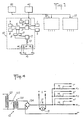
- - la figure 1 est un schéma bloc d'un circuit de commande et de régulation inclus dans un dispositif conforme à l'invention,
- - la figure 2 représente une vue schématique d'un exemple de structure à laquelle peut s'appliquer l'invention,
- - la figure 3 est un organigramme montrant le fonctionnement séquentiel d'un circuit de commande et de régulation selon l'invention, et
- - la figure 4 est un schéma d'un générateur de courant continu pouvant être utilisé dans le cadre de l'invention.
- FIG. 1 is a block diagram of a command and regulation circuit included in a device according to the invention,
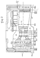
- FIG. 2 represents a schematic view of an example of a structure to which the invention can be applied,
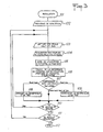
- FIG. 3 is a flow diagram showing the sequential operation of a command and regulation circuit according to the invention, and
- - Figure 4 is a diagram of a DC generator that can be used in the context of the invention.
On voit sur la figure 2 une structure métallique susceptible de jouer le rôle de cathode et pouvant ainsi faire l'objet d'une protection cathodique. Il s'agit à titre d'exemple d'une turbine 60 dite « au fil de l'eau placée dans un milieu aqueux 90 qui peut être un milieu marin et entourée d'une infrastructure 80. L'invention est cependant applicable à de nombreux autres types de structures métalliques susceptibles d'être immergées ou enterrées, par exemple des alternateurs, des conduites métalliques, des vannes ou des coques de navires.We see in Figure 2 a metal structure capable of playing the role of cathode and can thus be the subject of cathodic protection. This is, for example, a
Plusieurs groupes d'anodes A, à A,o sont disposés en diverses zones de la structure 60 à protéger. Chaque groupe d'anodes A (i étant un entier qui dans l'exemple considéré est compris entre 1 et 10) comprend plusieurs anodes Aij (avec j compris entre 1 et par exemple 12) alimentées à partir d'un même générateur de courant. La figure 2 ne montre que d'une façon globale les blocs d'alimentation 70 des divers groupes d'anodes. On voit sur la figure 2 les anodes An, A12, A13, A14 du groupe A, et les anodes A2,, A22, A23, A24, A25, A26, A27, A28 du groupe A2.Several groups of anodes A, A, o are arranged in various zones of the
Chaque anode Aij est isolée de la structure métallique 60 qui joue elle-même le rôle de cathode et se trouve en contact avec l'électrolyte 90. Les anodes Aij peuvent être placées en relief sur la structure métallique 60, avec interposition d'un élément d'isolation entre la structure 60 et chaque anode Aij. Les anodes Aij peuvent également être encastrées et être disposées alors non pas directement sur la structure métallique 60 mais dans le béton du génie civil de l'ouvrage à protéger. De telles anodes sont alors constituées chacune d'une pièce métallique encastrée dans une semelle en matière plastique et munie d'une connexion étanche, l'ensemble étant placé dans un logement prévu à cet effet.Each anode A ij is isolated from the
Les anodes Aij d'un groupe A sont placées de manière à assurer une bonne répartition du champ électrique au sein de l'électrolyte 90. Les différents groupes d'anodes A1 à A10 correspondent à différentes parties de la machine à protéger par exemple à différents sous-ensembles de la structure métallique d'un groupe turboalternateur comme représenté sur la figure 2.The anodes A ij of a group A are placed so as to ensure a good distribution of the electric field within the electrolyte 90. The different groups of anodes A 1 to A 10 correspond to different parts of the machine to be protected, for example to different sub-assemblies of the metallic structure of a turbo alternator group as shown in the figure 2.
Un groupe d'au moins deux électrodes de référence est disposé au voisinage de chaque groupe d'anodes - On a repéré sur la figure 2 par les références ER1 à ER10 les paires d'électrodes de référence associées aux groupes d'anodes A1 à A10 respectivement.A group of at least two reference electrodes is arranged in the vicinity of each group of anodes. The pairs of reference electrodes associated with the groups of anodes A 1 to 2 have been identified in FIG. 2 by the references ER1 to ER10. A 10 respectively.
On sait que dans les milieux dont la composition varie fortement au cours du temps, le potentiel des électrodes de référence n'est pas stable car il dépend de la concentration de l'ion réagissant dans le processus de formation du potentiel d'électrode (par exemple l'ion chlore pour les électrodes Mercure/Calomel ou celles à l'Argent/chlorure d'Argent).It is known that in media whose composition varies greatly over time, the potential of the reference electrodes is not stable because it depends on the concentration of the ion reacting in the process of forming the electrode potential (by example the chlorine ion for the Mercury / Calomel electrodes or those with Silver / Silver chloride).
C'est la raison pour laquelle en remplacement des électrodes de référence standard on peut utiliser des électrodes de référence munies d'un réservoir rempli de cristaux de sel réagissant qui saturent la solution dans laquelle baigne l'électrode. La liaison entre la solution saturée et le milieu extérieur s'effectuant à travers un filtre poreux, la durée pendant laquelle l'électrode donne une indication stable dépend du taux de diffusion du filtre poreux et de la capacité en sel du réservoir de l'électrode. On peut toutefois-par ce moyen fabriquer des électrodes dont le fonctionnement est assuré pendant plus d'un an.This is the reason why, instead of standard reference electrodes, reference electrodes can be used fitted with a reservoir filled with reacting salt crystals which saturate the solution in which the electrode is bathed. Since the connection between the saturated solution and the external medium takes place through a porous filter, the period during which the electrode gives a stable indication depends on the diffusion rate of the porous filter and on the salt capacity of the electrode reservoir . However, it is possible by this means to manufacture electrodes whose operation is guaranteed for more than a year.
On se reportera maintenant à la figure 1 qui montre schématiquement un ensemble de circuits de commande et de régulation 10, 20, 30.... pouvant être utilisés en combinaison avec les groupes d'anodes Ai, A2, A3,... et les ensembles d'électrodes de référence ER1, ER2, ER3,... de la figure 2.Reference will now be made to FIG. 1 which schematically shows a set of control and
On rappelle que dans un système de protection de type cathodique par courant appliqué, on fait' circuler un courant continu entre des anodes plongées dans le sol ou le liquide entourant la structure métallique à protéger et ladite structure qui constitue une cathode. Il est important de maintenir la valeur du courant utilisé dans une plage de valeurs donnée. En effet, une valeur de courant trop faible n'est pas à même d'empêcher la corrosion de se poursuivre tandis qu'un courant trop important conduit à un gaspillage d'énergie électrique. Les électrodes de référence permettent précisément, par la mesure de la différence de potentiel existant entre celles-ci dont le potentiel est supposé stable et la structure à protéger dont le potentiel est variable, de surveiller si le courant appliqué est correct, trop élevé ou trop faible.It will be recalled that in a cathodic type protection system by applied current, a direct current is made to circulate between anodes immersed in the ground or the liquid surrounding the metallic structure to be protected and said structure which constitutes a cathode. It is important to maintain the value of the current used within a given range of values. Indeed, too low a current value is not able to prevent corrosion from continuing while too high current leads to a waste of electrical energy. The reference electrodes allow precisely, by measuring the potential difference existing between them whose potential is assumed to be stable and the structure to be protected whose potential is variable, to monitor whether the applied current is correct, too high or too low.
Dans les systèmes d'asservissement automatique connus, les signaux provenant des électrodes de référence sont amplifiés et servent à actionner des dispositifs qui modifient le courant appliqué continu provenant d'un générateur afin de maintenir en permanence le courant appliqué dans une plage de valeurs prédéterminées.In known automatic servo systems, the signals from the reference electrodes are amplified and are used to actuate devices which modify the direct applied current coming from a generator in order to permanently maintain the applied current within a predetermined range of values.
Comme cela a été indiqué plus haut, l'utilisation d'un asservissement à faible constante de temps assurant.la constance du potentiel de l'ouvrage à protéger à une valeur égale ou inférieure au potentiel maximal de protection cathodique conduit à installer un générateur de courant surdimensionné pour répondre à la demande maximale de courant, du fait que la demande de courant varie considérablement avec la vitesse de l'électrolyte en contact avec le métal à protéger, laquelle vitesse est non négligeable lorsqu'il s'agit par exemple d'un ouvrage en eau de mer agitée, et du fait que la formation de dépôts calcomagné- siens sur l'ouvrage à protéger est difficile à contrôler.As indicated above, the use of a low time constant servo ensuring the constancy of the potential of the structure to be protected at a value equal to or less than the maximum cathodic protection potential leads to installing a generator oversized current to meet the maximum current demand, since the current demand varies considerably with the speed of the electrolyte in contact with the metal to be protected, which speed is not negligible when it is for example of a structure in rough seawater, and the fact that the formation of calcium deposits on the structure to be protected is difficult to control.
Dans le cas où plusieurs circuits anodes-cathode sont disposés sur une même structure, un asservissement en continu entraîne de plus des oscillations du courant délivré par les générateurs.In the case where several anode-cathode circuits are arranged on the same structure, a continuous control furthermore causes oscillations of the current delivered by the generators.
C'est la raison pour laquelle chaque circuit de commande et de régulation 10, 20, 30 selon l'invention est commandé de façon cyclique pour adapter par pas en cours d'utilisation le courant de manière à amener par étapes le potentiel de l'ouvrage à protéger à l'intérieur d'une gamme de valeurs prédéterminées.This is the reason why each control and
On décrira ci-après le circuit de commande 10 associé au premier groupe d'anodes A1 et à l'ensemble ER1 d'électrodes de référence 1,2 placées sur la partie de la machine à protéger concernée par le générateur 12 délivrant un courant aux anodes A11 à A1n du groupe A,.The
Les électrodes de référence 1 et 2 sont reliées à un comparateur 3 qui mesure la différence de potentiel entre les 35 électrodes 1,2 et sélectionne l'électrode 1 ou 2 la plus électro-négative pour la commande de la régulation. Une seule électrode de référence 1 ou 2 est ainsi utilisée pour la commande de la régulation, mais la deuxième électrode de référence permet d'effectuer à chaque fois un contrôle des électrodes de référence 1,2 entre elles à l'aide du comparateur 3. Lorsque l'écart de potentiel mesuré par le comparateur 3 dépasse un seuil prédéterminé fixé par le circuit de seuil 4 relié au comparateur 3, une alarme 5 est déclenchée pour indiquer que l'une au moins des électrodes de référence 1,2 est déficiente.The
Le potentiel de l'électrode de référence 1 ou 2 sélectionnée par le comparateur 3 est appliqué à un second comparateur 6 qui effectue une double comparaison entre d'une part le potentiel fourni par le comparateur 3 et d'autre part des potentiels de valeur EH et EB constituant des seuils haut et bas et engendrés par des circuits 7 et 8 reliés au comparateur 6. Les seuils haut et bas EH et EB sont engendrés au moyen d'une tension de référence si l'on utilise un comparateur analogique 6 ou inscrits dans des mémoires si le comparateur 6 est de type numérique.The potential of the
Si la valeur du potentiel fourni par le comparateur 3 se trouve située entre les valeurs EH et EB le comparateur 6 ne délivre aucun signal aux relais 9 ou 11 chargés de commander la variation de la tension de sortie du générateur 12. Si la. valeur fournie par le comparateur 3 est plus négative que celle du seuil bas Es, la polarisation est excessive et un signal d'une durée fixe est appliqué au relais 11 qui commande une réduction d'une valeur fixée à l'avance (par exemple 0,2v) de la tension délivrée par le générateur 12.If the value of the potential provided by the comparator 3 is located between the values E H and E B the comparator 6 does not deliver any signal to the
Si la valeur fournie par le comparateur 3 est moins négative que celle du seuil haut EH, la polarisation est insuffisante et le relais 9 commande une augmentation de valeur fixe prédéterminée (par exemple également de 0,2v) de la tension délivrée par le générateur 12.If the value provided by the comparator 3 is less negative than that of the high threshold E H , the polarization is insufficient and the
Chaque cycle tel que décrit ci-dessus est initié soit par une horloge 40 dont la fréquence des cycles est adaptée à la durée de la polarisation électrochimique (cette fréquence pouvant être par exemple de deux cycles par jour), soit par un contact temporisé 50 en relation avec le fonctionnement de l'organe 60 à protéger. Le contact temporisé 50 peut ainsi se déclencher à chaque mise en marche de la machine.Each cycle as described above is initiated either by a
Comme représenté sur la figure 4, un générateur de courant continu 12 peut comprendre par exemple un auto-transformateur variable 121 alimentant par l'intermédiaire d'un transformateur 123 un circuit redresseur 124 qui est lui-même relié à un groupe d'anodes Ai. La mesure du courant I délivré par le circuit redresseur 124 est effectuée à l'aide d'un shunt 13 aux bornes duquel est connecté un ampèremètre 15.As shown in FIG. 4, a direct
Le rapport de transformation de l'auto-transformateur 121 peut être commandé par un système électro-mécanique avec un moteur 122 ou électronique à partir d'un micro-calculateur gérant le circuit de commande 10 afin de pouvoir imposer un courant fixé par le micro-calculateur à partir des informations fournies par les étapes de comparaison 3 et 6.The transformation ratio of the auto-
Des résistances 14 connectées en série entre le générateur 12 et les anodes A11 à A1n respectivement permettent de prélever des signaux représentatifs du courant appliqué à'chaque anode A11 à A1n du même groupe A, à partir du générateur 12.
Un dispositif de limitation de surintensité peut être associé au circuit de commande 10. La valeur du courant maximum que doit fournir le redresseur 124 étant mise en mémoire, une comparaison entre la valeur de courant maximum mémorisée et la valeur fournie par l'ampèremètre 15 ou les appareils de mesure connectés aux bornes des résistances 14 est effectuée à chaque cycle de réajustement du courant pendant la commande de la variation de l'auto-transformateur variable 121. Cette comparaison entraîne un ordre d'arrêt du mouvement du curseur de l'auto-transformateur 121 ou un mouvement inverse dont l'action limite ou réduit la tension appliquée par le redresseur 124 à une valeur telle que lors d'une modification par pas de la valeur du courant délivrée par le générateur 12 le courant ne dépasse pas le seuil prédéterminé de limitation de surintensité.An overcurrent limiting device can be associated with the
Un intérêt essentiel du système de commande selon l'invention réside dans l'ajustement pas à pas effectué au cours du temps des caractéristiques des redresseurs aux variations des conditions de polarisation cathodique, la sécurité du système étant assurée par le choix d'une électrode de référence parmi plusieurs 1,2 situées au voisinage l'une de l'autre.An essential interest of the control system according to the invention lies in the step-by-step adjustment made over time of the characteristics of the rectifiers to variations in the cathodic polarization conditions, the safety of the system being ensured by the choice of an electrode for reference among several 1.2 located in the vicinity of one another.
Cet ajustement pas à pas supprime la nécessité d'un contrôle et d'un réglage manuels. Par ailleurs, l'action cyclique permet d'intervenir sur plusieurs générateurs de protection cathodique commandant des groupes d'anodes A, à A,o susceptibles de s'influencer mutuellement.This step-by-step adjustment eliminates the need for manual control and adjustment. Furthermore, the cyclic action makes it possible to intervene on several cathodic protection generators controlling groups of anodes A, to A, o capable of influencing each other.
En procédant à des itérations successives et en choisissant l'ordre séquentiel de commande pas à pas des circuits de commande 10, 20, 30 ... associés aux différents groupes d'anodes A1, A2, A3.... il est possible de réduire les interférences des différents circuits entre eux sur le potentiel de l'ouvrage à protéger.By carrying out successive iterations and choosing the sequential order of control step by step of the
On a représenté sur la figure 3 un organigramme simplifié montrant le schéma fonctionnel de la régulation d'un dispositif de protection cathodique selon l'invention mettant en oeuvre plusieurs groupes A d'anodes Aij.FIG. 3 shows a simplified flowchart showing the functional diagram of the regulation of a cathodic protection device according to the invention using several groups A of anodes A ij .
L'étape 101 correspond à l'initialisation de la régulation. L'étape 102 définit une fréquence de scrutation qui conditionne le comportement cyclique et doit être adaptée aux conditions de fonctionnement. Cette fréquence de scrutation correspond à la fréquence de l'horloge 40 de la figure 1 et peut être de l'ordre de un ou deux cycles par jour. L'initialisation de la régulation peut toutefois être également commandée par le relais temporisé 50 actionné par exemple à la mise en marche de la machine ou à la mise en oeuvre d'une opération particulière, telle que par exemple une opération de pompage, qui assure que la séquence d'ajustement du courant sera toujours effectuée dans des conditions similaires de polarisation.Step 101 corresponds to the initialization of the regulation. Step 102 defines a polling frequency which conditions the cyclic behavior and must be adapted to the operating conditions. This scanning frequency corresponds to the frequency of the
Le schéma de régulation comprend une série de boucles de scrutation dont le nombre est fonction de la fréquence de scrutation, avec un test 111 de fin de boucle de scrutation qui détermine la fin 112 d'un cycle de régulation.The regulation scheme includes a series of polling loops, the number of which depends on the polling frequency, with a
Pour chaque boucle de scrutation, une ou plusieurs boucles de groupe sont effectuées selon que le dispositif de protection cathodique comprend un ou plusieurs groupes d'anodes.For each scanning loop, one or more group loops are performed depending on whether the cathodic protection device comprises one or more groups of anodes.
Pour chaque boucle de groupe correspondant à un groupe d'anodes A;, l'étape 103 correspond à la lecture des seuils haut et bas EHi et EBi qui définissent une fourchette de potentiel adaptée aux conditions particulières de dépolarisation au voisinage du groupe d'électrodes considéré. L'étape 104 correspond à l'acquisition des couples de potentiels d'électrode ELi1 et ELi2 correspondant aux deux électrodes de référence 1, 2 associées au circuit de commande du groupe considéré A.For each group loop corresponding to a group of anodes A;,
L'étape 105 d'une boucle de groupe correspond au choix de l'électrode 1 ou 2 à potentiel le plus bas par comparaison des valeurs de potentiels d'électrodes de référence ELi1 et ELi2. On n'a pas représenté sur l'organigramme l'étape facultative consistant à comparer la valeur absolue de la différence ELi1-ELi2 à un seuil déterminé et à déclencher une alarme en cas de dépassement de ce seuil (circuits 4 et 5 de la figure 1).Step 105 of a group loop corresponds to the choice of the
L'étape 106 d'une boucle de groupe correspond au calcul de la différence de potentiel entre la structure à protéger 60 et le potentiel de l'électrode de référence retenue à l'étape 105.Step 106 of a group loop corresponds to the calculation of the potential difference between the structure to be protected 60 and the potential of the reference electrode used in
L'étape 107 consiste en un double test avec une comparaison de la valeur calculée à l'étape 106 avec d'une part le seuil haut EHi et d'autre part le seuil bas EBi lus à l'étape 103. Si la valeur de différence de potentiel calculée est supérieure au seuil haut EHi, l'étape suivante est l'étape 108 consistant à diminuer d'un pas la valeur du courant délivré par le générateur de courant 12 de la boucle considérée.Step 107 consists of a double test with a comparison of the value calculated in step 106 with on the one hand the high threshold EHi and on the other hand the low threshold EBi read in
Si la valeur de différence de potentiel calculée est inférieure au seuil bas EBi, l'étape suivante est l'étape 109 consistant à augmenter d'un pas la valeur du courant délivré par le générateur de courant 12 de la boucle considérée. Après l'étape 108 ou l'étape 109, ou si la valeur de différence de potentiel calculée est comprise entre les seuils bas et haut EBi et EHi, le test de fin de boucle de groupe 110 est exécuté.If the calculated potential difference value is less than the low threshold EBi, the next step is
Claims (8)
Priority Applications (2)
| Application Number | Priority Date | Filing Date | Title |
|---|---|---|---|
| IN650/DEL/86A IN168063B (en) | 1985-07-23 | 1986-07-21 | |
| AT86401638T ATE42579T1 (en) | 1985-07-23 | 1986-07-22 | DEVICE FOR THE CATHODIC PROTECTION OF AN INSTALLATION USING PRESSURE CURRENT. |
Applications Claiming Priority (2)
| Application Number | Priority Date | Filing Date | Title |
|---|---|---|---|
| FR8511259A FR2589486B1 (en) | 1985-07-23 | 1985-07-23 | DEVICE FOR THE CATHODIC PROTECTION OF AN APPLIED CURRENT STRUCTURE |
| FR8511259 | 1985-07-23 |
Publications (2)
| Publication Number | Publication Date |
|---|---|
| EP0210920A1 EP0210920A1 (en) | 1987-02-04 |
| EP0210920B1 true EP0210920B1 (en) | 1989-04-26 |
Family
ID=9321556
Family Applications (1)
| Application Number | Title | Priority Date | Filing Date |
|---|---|---|---|
| EP86401638A Expired EP0210920B1 (en) | 1985-07-23 | 1986-07-22 | Apparatus for the cathodic protection of a structure by an applied current |
Country Status (9)
| Country | Link |
|---|---|
| US (1) | US4713158A (en) |
| EP (1) | EP0210920B1 (en) |
| KR (1) | KR870001335A (en) |
| CN (1) | CN86105112A (en) |
| AU (1) | AU582979B2 (en) |
| CA (1) | CA1282368C (en) |
| DE (1) | DE3663040D1 (en) |
| FR (1) | FR2589486B1 (en) |
| NZ (1) | NZ216935A (en) |
Families Citing this family (21)
| Publication number | Priority date | Publication date | Assignee | Title |
|---|---|---|---|---|
| DE4025088A1 (en) * | 1990-08-08 | 1992-02-13 | Vaw Ver Aluminium Werke Ag | CATHODICAL CORROSION PROTECTION FOR AN ALUMINUM CONTAINING SUBSTRATE |
| ES2042415B1 (en) * | 1992-05-07 | 1997-02-01 | W W I Proytec S L | PRINTED CURRENT CATHODIC PROTECTION SYSTEM FOR METAL PARTS OF VESSELS. |
| FI119150B (en) | 1999-05-17 | 2008-08-15 | Savcor Process Oy | A method for implementing electrochemical corrosion inhibition under changing conditions |
| US6183625B1 (en) * | 1999-11-08 | 2001-02-06 | Brunswick Corporation | Marine galvanic protection monitor |
| US7064459B1 (en) * | 2001-08-20 | 2006-06-20 | Brunswick Corporation | Method of inhibiting corrosion of a component of a marine vessel |
| US7189319B2 (en) * | 2004-02-18 | 2007-03-13 | Saudi Arabian Oil Company | Axial current meter for in-situ continuous monitoring of corrosion and cathodic protection current |
| KR100595391B1 (en) * | 2004-03-24 | 2006-06-30 | 코렐테크놀로지(주) | Device of electricity anticorrosion |
| EP1722011A1 (en) * | 2005-05-11 | 2006-11-15 | Siemens Aktiengesellschaft | Turbine component, electrical system with such a turbine component, combustor, turbine and method for reducing the corrosion in a turbine component. |
| US9335065B2 (en) * | 2013-04-25 | 2016-05-10 | General Electric Company | System and method for adjusting anode rod galvanic corrosion |
| JP2014218731A (en) * | 2013-05-10 | 2014-11-20 | 東京瓦斯株式会社 | Cathodic protection of pipeline and cathodic protection device |
| US9372012B2 (en) * | 2013-05-10 | 2016-06-21 | General Electric Company | Determining heating element and water heater status based on galvanic current |
| DE102013212725A1 (en) * | 2013-06-28 | 2014-12-31 | Ksb Aktiengesellschaft | Fluid-carrying system with cathodic corrosion protection |
| CN105463474B (en) * | 2014-08-18 | 2018-11-30 | 北京纳米能源与系统研究所 | A kind of driving metal erosion means of defence and system certainly |
| US10633746B2 (en) * | 2017-07-07 | 2020-04-28 | Vector Remediation Ltd. | Cathodic corrosion protection with current limiter |
| US20210292916A1 (en) * | 2017-07-07 | 2021-09-23 | Vector Remediation Ltd. | Cathodic Corrosion Protection with Current Limiter |
| FR3072456B1 (en) * | 2017-10-16 | 2022-04-29 | Safran Aircraft Engines | PROTECTION SYSTEM AGAINST CORROSION OF ALUMINUM PARTS OF A TURBOMACHINE |
| CN108823575B (en) * | 2018-08-22 | 2023-08-18 | 中国石油天然气集团有限公司 | Cluster well cathode protection direct current distribution device, manufacturing method and protection method |
| CN109371402A (en) * | 2018-12-10 | 2019-02-22 | 美钻深海能源科技研发(上海)有限公司 | A kind of adjustable cathodic protection by rectifier system |
| CN112760653B (en) * | 2019-11-01 | 2023-01-10 | 中国石油天然气股份有限公司 | Current control method and device in cathodic protection system |
| CN111876786B (en) * | 2020-06-19 | 2022-07-05 | 中国石油天然气股份有限公司 | Remote monitoring method and device for cathode protection of buried pipeline |
| CN112941521B (en) * | 2021-01-28 | 2022-09-23 | 中国安全生产科学研究院 | Cathodic protection system of oil gas pipeline |
Family Cites Families (9)
| Publication number | Priority date | Publication date | Assignee | Title |
|---|---|---|---|---|
| DE1161738B (en) * | 1958-12-19 | 1964-01-23 | Rolland Clifford Sabins | Arrangement for the automatic regulation of the external current in systems for cathodic corrosion protection |
| US2985512A (en) * | 1959-04-14 | 1961-05-23 | Exxon Research Engineering Co | Manufacture of hydrogen |
| SE314877B (en) * | 1963-12-28 | 1969-09-15 | Stocznia Im Komuny Paryskiej | |
| US3425921A (en) * | 1966-04-04 | 1969-02-04 | Wallace & Tiernan Inc | Methods and systems for protecting metal structures |
| US3676319A (en) * | 1969-03-28 | 1972-07-11 | Radiometer As | Electrode, half cell and electrode component for the measurement of electromotive force |
| US3634222A (en) * | 1970-05-13 | 1972-01-11 | Engelhard Min & Chem | Sampling and control system for cathodic protection |
| US3714004A (en) * | 1970-12-02 | 1973-01-30 | Continental Oil Co | Method and apparatus for cathodic protection |
| GB1589739A (en) * | 1977-06-28 | 1981-05-20 | Hughes & Co | Impressed current cathodic protection |
| US4437957A (en) * | 1982-05-03 | 1984-03-20 | Freeman Industries, Inc. | Cathodic or anodic protection system and method for independently protecting different regions of a structure |
-
1985
- 1985-07-23 FR FR8511259A patent/FR2589486B1/en not_active Expired - Lifetime
-
1986
- 1986-07-21 US US06/887,214 patent/US4713158A/en not_active Expired - Fee Related
- 1986-07-22 EP EP86401638A patent/EP0210920B1/en not_active Expired
- 1986-07-22 DE DE8686401638T patent/DE3663040D1/en not_active Expired
- 1986-07-22 KR KR1019860005941A patent/KR870001335A/en not_active Application Discontinuation
- 1986-07-22 AU AU60421/86A patent/AU582979B2/en not_active Ceased
- 1986-07-22 CN CN198686105112A patent/CN86105112A/en active Pending
- 1986-07-22 NZ NZ216935A patent/NZ216935A/en unknown
- 1986-07-23 CA CA000514516A patent/CA1282368C/en not_active Expired - Lifetime
Also Published As
| Publication number | Publication date |
|---|---|
| AU582979B2 (en) | 1989-04-13 |
| FR2589486A1 (en) | 1987-05-07 |
| CA1282368C (en) | 1991-04-02 |
| NZ216935A (en) | 1989-02-24 |
| EP0210920A1 (en) | 1987-02-04 |
| CN86105112A (en) | 1987-05-13 |
| DE3663040D1 (en) | 1989-06-01 |
| AU6042186A (en) | 1987-01-29 |
| US4713158A (en) | 1987-12-15 |
| FR2589486B1 (en) | 1991-09-06 |
| KR870001335A (en) | 1987-03-13 |
Similar Documents
| Publication | Publication Date | Title |
|---|---|---|
| EP0210920B1 (en) | Apparatus for the cathodic protection of a structure by an applied current | |
| Taylor et al. | Electrochemical studies on glassy carbon electrodes: I. Electron transfer kinetics | |
| US7585397B2 (en) | Automatic potential control cathodic protection system for storage tanks | |
| JP7210539B2 (en) | Cathodic protection for offshore wind turbine steel support structures | |
| FR2898978A1 (en) | POTENTIAL MEASUREMENT CELL FOR THE MONITORING OF FACILITIES WITH CATHODIC PROTECTION BY STRAINING | |
| NO152478B (en) | SYNCHRONIZER DEVICE FOR TIME MULTIPLE SYSTEM | |
| FR2465789A1 (en) | MAGNESIUM ALLOYS AND THEIR USE IN ELECTROLYTIC CELLS SUCH AS BATTERY BATTERIES | |
| US4257856A (en) | Electrolytic process useful for the electrolysis of water | |
| Harris et al. | Characterized Semiconductor Electrodes: II. Room Temperature Diffusion in a Single Crystal Rutile Electrode | |
| EP0065901A1 (en) | Potentiometric transducer system | |
| EP2944614B1 (en) | Method and apparatus for treating scale in a pipeline | |
| EP3938561B1 (en) | Device for forming concretions with regulated autonomous source | |
| Dumont et al. | Dissolution and passivation processes in the corrosion of copper and nickel in KF. 2HF at 85 C | |
| RU2376401C2 (en) | Method of measurement of polarisation potential of underground metallic structure and device for its implementation | |
| De Oliveira et al. | Early stages of the lead-acid battery discharge | |
| FR3110297A3 (en) | Power balancing method, system and device in an electrical network | |
| Burke et al. | Anomalous oxidation reactions at noble metal surfaces at low potentials: with particular reference to palladium | |
| FR3110296A1 (en) | Power balancing method, system and device in an electrical network | |
| Bardarov et al. | Sediment microbial fuel cell utilizing river sediments and soil | |
| EP1241280A1 (en) | Process and apparatus for the cathodic protection of a metal structure | |
| FR3002693A1 (en) | ENERGY STORAGE DEVICE AND METHOD OF MANAGING THE SAME | |
| Spirin et al. | Electrochemical protection against corrosion of underwater structures of the VI Lenin Mingechaur hydroelectric station | |
| Motoda et al. | Power density profile of biofilm battery composed of stainless steel cathode and aluminum anode | |
| WO2016173968A2 (en) | Method for electrically charging a battery using an intermittent energy source and corresponding charge control device | |
| FR2468657A1 (en) | METHOD AND DEVICE FOR PROTECTING METALS AGAINST UNDESIRABLE CHEMICAL METALLIZATION, IN PARTICULAR, AGAINST NICKELING |
Legal Events
| Date | Code | Title | Description |
|---|---|---|---|
| PUAI | Public reference made under article 153(3) epc to a published international application that has entered the european phase |
Free format text: ORIGINAL CODE: 0009012 |
|
| AK | Designated contracting states |
Kind code of ref document: A1 Designated state(s): AT BE CH DE GB IT LI LU NL SE |
|
| 17P | Request for examination filed |
Effective date: 19870724 |
|
| 17Q | First examination report despatched |
Effective date: 19880914 |
|
| GRAA | (expected) grant |
Free format text: ORIGINAL CODE: 0009210 |
|
| STAA | Information on the status of an ep patent application or granted ep patent |
Free format text: STATUS: THE PATENT HAS BEEN GRANTED |
|
| AK | Designated contracting states |
Kind code of ref document: B1 Designated state(s): AT BE CH DE GB IT LI LU NL SE |
|
| REF | Corresponds to: |
Ref document number: 42579 Country of ref document: AT Date of ref document: 19890515 Kind code of ref document: T |
|
| ITF | It: translation for a ep patent filed | ||
| GBT | Gb: translation of ep patent filed (gb section 77(6)(a)/1977) | ||
| REF | Corresponds to: |
Ref document number: 3663040 Country of ref document: DE Date of ref document: 19890601 |
|
| PLBE | No opposition filed within time limit |
Free format text: ORIGINAL CODE: 0009261 |
|
| 26N | No opposition filed | ||
| REG | Reference to a national code |
Ref country code: GB Ref legal event code: 746 |
|
| PGFP | Annual fee paid to national office [announced via postgrant information from national office to epo] |
Ref country code: AT Payment date: 19920624 Year of fee payment: 7 |
|
| PGFP | Annual fee paid to national office [announced via postgrant information from national office to epo] |
Ref country code: CH Payment date: 19920708 Year of fee payment: 7 |
|
| PGFP | Annual fee paid to national office [announced via postgrant information from national office to epo] |
Ref country code: GB Payment date: 19920714 Year of fee payment: 7 |
|
| PGFP | Annual fee paid to national office [announced via postgrant information from national office to epo] |
Ref country code: LU Payment date: 19920722 Year of fee payment: 7 Ref country code: DE Payment date: 19920722 Year of fee payment: 7 |
|
| PGFP | Annual fee paid to national office [announced via postgrant information from national office to epo] |
Ref country code: SE Payment date: 19920724 Year of fee payment: 7 |
|
| ITTA | It: last paid annual fee | ||
| PGFP | Annual fee paid to national office [announced via postgrant information from national office to epo] |
Ref country code: NL Payment date: 19920731 Year of fee payment: 7 |
|
| PGFP | Annual fee paid to national office [announced via postgrant information from national office to epo] |
Ref country code: BE Payment date: 19920812 Year of fee payment: 7 |
|
| EPTA | Lu: last paid annual fee | ||
| PG25 | Lapsed in a contracting state [announced via postgrant information from national office to epo] |
Ref country code: LU Free format text: LAPSE BECAUSE OF NON-PAYMENT OF DUE FEES Effective date: 19930722 Ref country code: GB Effective date: 19930722 Ref country code: AT Effective date: 19930722 |
|
| PG25 | Lapsed in a contracting state [announced via postgrant information from national office to epo] |
Ref country code: SE Effective date: 19930723 |
|
| PG25 | Lapsed in a contracting state [announced via postgrant information from national office to epo] |
Ref country code: LI Effective date: 19930731 Ref country code: CH Effective date: 19930731 Ref country code: BE Effective date: 19930731 |
|
| BERE | Be: lapsed |
Owner name: GAZ DE FRANCE Effective date: 19930731 |
|
| PG25 | Lapsed in a contracting state [announced via postgrant information from national office to epo] |
Ref country code: NL Effective date: 19940201 |
|
| NLV4 | Nl: lapsed or anulled due to non-payment of the annual fee | ||
| GBPC | Gb: european patent ceased through non-payment of renewal fee |
Effective date: 19930722 |
|
| REG | Reference to a national code |
Ref country code: CH Ref legal event code: PL |
|
| PG25 | Lapsed in a contracting state [announced via postgrant information from national office to epo] |
Ref country code: DE Effective date: 19940401 |
|
| EUG | Se: european patent has lapsed |
Ref document number: 86401638.1 Effective date: 19940210 |
|
| PG25 | Lapsed in a contracting state [announced via postgrant information from national office to epo] |
Ref country code: IT Free format text: LAPSE BECAUSE OF NON-PAYMENT OF DUE FEES;WARNING: LAPSES OF ITALIAN PATENTS WITH EFFECTIVE DATE BEFORE 2007 MAY HAVE OCCURRED AT ANY TIME BEFORE 2007. THE CORRECT EFFECTIVE DATE MAY BE DIFFERENT FROM THE ONE RECORDED. Effective date: 20050722 |