EP0209727B1 - Procédé et spectromètre pour la détermination de la puissance de micro-ondes dans un guide d'ondes creux surdimensionné - Google Patents
Procédé et spectromètre pour la détermination de la puissance de micro-ondes dans un guide d'ondes creux surdimensionné Download PDFInfo
- Publication number
- EP0209727B1 EP0209727B1 EP86108332A EP86108332A EP0209727B1 EP 0209727 B1 EP0209727 B1 EP 0209727B1 EP 86108332 A EP86108332 A EP 86108332A EP 86108332 A EP86108332 A EP 86108332A EP 0209727 B1 EP0209727 B1 EP 0209727B1
- Authority
- EP
- European Patent Office
- Prior art keywords
- waveguide
- coupling
- out structure
- spectrometer according
- antenna
- Prior art date
- Legal status (The legal status is an assumption and is not a legal conclusion. Google has not performed a legal analysis and makes no representation as to the accuracy of the status listed.)
- Expired
Links
Images

Classifications
-
- G—PHYSICS
- G01—MEASURING; TESTING
- G01R—MEASURING ELECTRIC VARIABLES; MEASURING MAGNETIC VARIABLES
- G01R21/00—Arrangements for measuring electric power or power factor
- G01R21/01—Arrangements for measuring electric power or power factor in circuits having distributed constants
Definitions
- the invention relates to a method for determining the microwave power in the spectrum of the wave modes going in and out in an oversized microwave waveguide according to the preamble of claim 1 and a spectrometer that can be used to carry out this method.
- the width of rectangular waveguides or the diameter of round waveguides is significantly larger than the vacuum wavelength of the microwaves transported, then it is oversized waveguides in which, as is known, in addition to the main mode, i.a. due to geometrical imperfections of the waveguide, a spectrum of several other modes (wave types) with different axial wave numbers can spread.
- extremely oversized waveguides must be used to avoid breakdowns.
- a circular waveguide with a diameter of 28 mm is used to heat a plasma using a gyrotron that generates an output of 200 kW at 70 GHz, in which 110 different types of waves can already occur.
- the individual modes generally have different outputs, and it is often necessary to determine the output of the different modes.
- the invention has for its object to provide a method and a spectrometer that enable the determination of the performance of the mode spectrum with the desired mode selectivity with less mechanical effort than before and in particular without the need for multiple coupling structures (directional couplers).
- the invention makes it possible to measure the entire spectrum of the waveguide modes going back and forth with only one coupling structure, the mechanical precision of which does not impose any particularly high demands. It is also advantageous that waves going back and forth do not interfere in the measuring system.
- the power measurement is not limited to a "monochromatic" system with only one transmission frequency, as before, but it can also be carried out on waveguides in which there is a frequency mixture if frequency-selective reception devices are used or the antenna signal is evaluated frequency-selectively.
- the invention makes use of the knowledge that the power of each mode is emitted at the decoupling structure at its own angle and that the respective mode can be inferred from the respective angle, as will be explained below using an exemplary embodiment of a suitable wavenumber spectrometer.
- the spectrometer is simplified and shown schematically in the drawing.
- the decoupling structure for identifying the most important modes can be, for example, 400 mm long.
- a longitudinal slot in the waveguide which may form the decoupling structure.
- the receiving antenna can also be arranged in the far area lying beyond the near field mentioned, that is to say at a greater distance from the coupling-out structure 2.
- a simple, i.e. Non-directionally selective receiving antenna for intensity measurement since the individual radiations are sufficiently separated from each other in the far range.
- the radiation space between the coupling-out structure 2 and the antennas 3 is delimited by lateral walls 4 made of absorbent material parallel to the radiation plane.
- the outcoupled waves can be guided between metal plates or in a dielectric layer before they are emitted.
- the intensity of the radiation field at the receiving antenna can thus be increased.
- the arm 6 with the receiving antenna 3 is continuously pivoted over its entire angular range from 0 to 180 ° with respect to the waveguide axis, and the power measured in each case is registered with assignment to the individual angles. In the simplest case, this can be done by swiveling the arm by hand and simultaneously recording the measured power in a table or curve.
- the antenna 3 is preferably adjusted by a drive device (not shown) which is connected to a motor and which is synchronized with the power measurement device connected to the antenna 3, ie is coupled via a feedback system, for example to an automatic recorder or computer.
- the second receiving antenna 3 shown on the arm 7 is not absolutely necessary for the measurement. However, at a selected angular position, it can serve to generate a reference signal during the measurement.
- Another possibility is to measure two modes simultaneously with the two receiving antennas. Finally, it is also possible to measure the power of each mode in the forward direction with one antenna and that in the return direction with the other antenna.
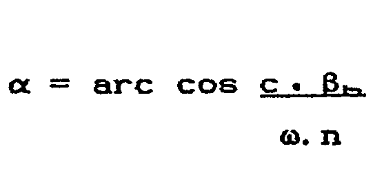
- the coupling-out angle a which is characteristic of the respective mode, is measured with respect to the direction of propagation in the waveguide and is (for hole spacing smaller than V2) always smaller than 90 ° .
- the invention is not restricted to any particular transparency.
- the Gaussian-shaped one can also choose, for example, a cosine or rectangular radiation pattern, as is known per se from transmitter antenna technology (e.g. leaky-wave antennas).
- transmitter antenna technology e.g. leaky-wave antennas
- the outcoupled waves are not radiated into a coupling waveguide as before, but in the space outside the waveguide 1, which may be delimited by the shielding walls 4. From each of the holes 5, which is in principle a small, strongly damping waveguide with a length corresponding to the opening depth, a small elementary wave with a specific phase relationship corresponds to the wavelength in the waveguide.
- the respective mode can be identified from the measured angle a using the above equation for known waveguide dimensions.
- a hole spacing is smaller than ⁇ 0/2. If there is a medium with the refractive index n outside the waveguide, then the above-mentioned relationship between a and ⁇ h follows for the coupling-out angle a.
Landscapes
- Engineering & Computer Science (AREA)
- Power Engineering (AREA)
- Physics & Mathematics (AREA)
- General Physics & Mathematics (AREA)
- Waveguide Aerials (AREA)
Claims (14)
Applications Claiming Priority (2)
| Application Number | Priority Date | Filing Date | Title |
|---|---|---|---|
| DE19853525918 DE3525918A1 (de) | 1985-07-19 | 1985-07-19 | Verfahren und spektrometer zum bestimmen der mikrowellenleistung in einem ueberdimensionierten mikrowellen-hohlleiter |
| DE3525918 | 1985-07-19 |
Publications (2)
| Publication Number | Publication Date |
|---|---|
| EP0209727A1 EP0209727A1 (fr) | 1987-01-28 |
| EP0209727B1 true EP0209727B1 (fr) | 1989-11-08 |
Family
ID=6276258
Family Applications (1)
| Application Number | Title | Priority Date | Filing Date |
|---|---|---|---|
| EP86108332A Expired EP0209727B1 (fr) | 1985-07-19 | 1986-06-19 | Procédé et spectromètre pour la détermination de la puissance de micro-ondes dans un guide d'ondes creux surdimensionné |
Country Status (2)
| Country | Link |
|---|---|
| EP (1) | EP0209727B1 (fr) |
| DE (2) | DE3525918A1 (fr) |
Families Citing this family (1)
| Publication number | Priority date | Publication date | Assignee | Title |
|---|---|---|---|---|
| DE3532214A1 (de) * | 1985-09-10 | 1987-04-16 | Kernforschungsz Karlsruhe | Verfahren zur bestimmung der in einem wellenleiter vorhandenen moden und anordnung zur durchfuehrung des verfahrens |
Family Cites Families (2)
| Publication number | Priority date | Publication date | Assignee | Title |
|---|---|---|---|---|
| US2479650A (en) * | 1944-11-01 | 1949-08-23 | Philco Corp | Selective wave guide energy meter |
| US3327211A (en) * | 1963-02-07 | 1967-06-20 | Cutler Hammer Inc | Multi-mode microwave power measurement utilizing oversized measuring waveguide section to obtain plane wave propagation |
-
1985
- 1985-07-19 DE DE19853525918 patent/DE3525918A1/de active Granted
-
1986
- 1986-06-19 DE DE8686108332T patent/DE3666875D1/de not_active Expired
- 1986-06-19 EP EP86108332A patent/EP0209727B1/fr not_active Expired
Also Published As
| Publication number | Publication date |
|---|---|
| EP0209727A1 (fr) | 1987-01-28 |
| DE3666875D1 (en) | 1989-12-14 |
| DE3525918C2 (fr) | 1989-02-16 |
| DE3525918A1 (de) | 1987-01-29 |
Similar Documents
| Publication | Publication Date | Title |
|---|---|---|
| DE69126793T2 (de) | Optische anordnung | |
| DE68914360T2 (de) | Sende- und Empfangsvorrichtung für Mikrowellenstrahlung zur Abbildung von verdeckten Gegenständen. | |
| DE3486164T2 (de) | Resonanzhohlleiterschalter für strahlende Öffnung. | |
| Altschuler et al. | Discontinuities in the center conductor of symmetric strip transmission line | |
| Keilmann | Infrared high-pass filter with high contrast | |
| EP0082560B1 (fr) | Dispositif de mesure de l'humidité | |
| US5128621A (en) | Device for measuring, at a plurality of points, the microwave field diffracted by an object | |
| DE844177C (de) | Anordnung zur Verringerung der Phasengeschwindigkeit elektromagnetischer Wellen | |
| DE3587959T2 (de) | Akustischer Oberflächenwellen-Spektrumanalysator. | |
| DE2941563A1 (de) | Hohlleiter-anordnung | |
| DE112017001223B4 (de) | Verzögerungsschaltung | |
| DE69714014T2 (de) | Strahlungsfeld-analysevorrichtung | |
| DE2460552A1 (de) | Hornstrahler mit anordnung zur entnahme von der ablagemessung dienenden wellentypen | |
| DE2712600C2 (de) | Vorrichtung zum Erfassen einer plötzlichen Veränderung der von Holzgut durchgelassenen oder reflektierten Energie mit Hochfrequenz | |
| Stephenson et al. | Endfire slot antennas | |
| EP0209727B1 (fr) | Procédé et spectromètre pour la détermination de la puissance de micro-ondes dans un guide d'ondes creux surdimensionné | |
| DE69419380T2 (de) | Kompakte und tragbare Vorrichtung zur Messung des Reflektionskoeffizienten einer mit Mikrowellen bestrahlten Struktur | |
| DE112023002198T5 (de) | Verwalten der Leistungfähigkeit eines optischen Phased-Arrays basierend auf Winkelintensitätsverteilungen | |
| DE1962436C1 (de) | Dopplernavigations-Radarantenne mit automatischer Land- See- Fehlerkorrektur auf Grund unterschiedlich geneigter Keulengruppen | |
| DE69618741T2 (de) | Elektomagnetische Linse in Form einer auf einem getragenen Substrat gedruckten Schaltung | |
| DE2525358C3 (de) | RUlentrichterstrahler | |
| Warters | The effects of mode filters on the transmission characteristics of circular electric waves in a circular waveguide | |
| Kai et al. | Analysis of inner fields and aperture illumination of an oversize rectangular slotted waveguide | |
| DE102022123851A1 (de) | Radar zur Messung eines Abstands zu einem Messobjekt nach dem Laufzeitprinzip | |
| Sangster | Slotted waveguide linear array with polarisation control |
Legal Events
| Date | Code | Title | Description |
|---|---|---|---|
| PUAI | Public reference made under article 153(3) epc to a published international application that has entered the european phase |
Free format text: ORIGINAL CODE: 0009012 |
|
| AK | Designated contracting states |
Kind code of ref document: A1 Designated state(s): CH DE FR GB IT LI NL |
|
| 17P | Request for examination filed |
Effective date: 19870224 |
|
| 17Q | First examination report despatched |
Effective date: 19890309 |
|
| GRAA | (expected) grant |
Free format text: ORIGINAL CODE: 0009210 |
|
| AK | Designated contracting states |
Kind code of ref document: B1 Designated state(s): CH DE FR GB IT LI NL |
|
| GBT | Gb: translation of ep patent filed (gb section 77(6)(a)/1977) | ||
| REF | Corresponds to: |
Ref document number: 3666875 Country of ref document: DE Date of ref document: 19891214 |
|
| ITF | It: translation for a ep patent filed | ||
| ET | Fr: translation filed | ||
| PLBE | No opposition filed within time limit |
Free format text: ORIGINAL CODE: 0009261 |
|
| STAA | Information on the status of an ep patent application or granted ep patent |
Free format text: STATUS: NO OPPOSITION FILED WITHIN TIME LIMIT |
|
| 26N | No opposition filed | ||
| ITTA | It: last paid annual fee | ||
| PGFP | Annual fee paid to national office [announced via postgrant information from national office to epo] |
Ref country code: CH Payment date: 20000526 Year of fee payment: 15 |
|
| PGFP | Annual fee paid to national office [announced via postgrant information from national office to epo] |
Ref country code: GB Payment date: 20000614 Year of fee payment: 15 |
|
| PGFP | Annual fee paid to national office [announced via postgrant information from national office to epo] |
Ref country code: NL Payment date: 20000630 Year of fee payment: 15 Ref country code: FR Payment date: 20000630 Year of fee payment: 15 |
|
| PGFP | Annual fee paid to national office [announced via postgrant information from national office to epo] |
Ref country code: DE Payment date: 20000823 Year of fee payment: 15 |
|
| PG25 | Lapsed in a contracting state [announced via postgrant information from national office to epo] |
Ref country code: GB Free format text: LAPSE BECAUSE OF NON-PAYMENT OF DUE FEES Effective date: 20010619 |
|
| PG25 | Lapsed in a contracting state [announced via postgrant information from national office to epo] |
Ref country code: LI Free format text: LAPSE BECAUSE OF NON-PAYMENT OF DUE FEES Effective date: 20010630 Ref country code: CH Free format text: LAPSE BECAUSE OF NON-PAYMENT OF DUE FEES Effective date: 20010630 |
|
| PG25 | Lapsed in a contracting state [announced via postgrant information from national office to epo] |
Ref country code: NL Free format text: LAPSE BECAUSE OF NON-PAYMENT OF DUE FEES Effective date: 20020101 |
|
| GBPC | Gb: european patent ceased through non-payment of renewal fee |
Effective date: 20010619 |
|
| REG | Reference to a national code |
Ref country code: CH Ref legal event code: PL |
|
| PG25 | Lapsed in a contracting state [announced via postgrant information from national office to epo] |
Ref country code: FR Free format text: LAPSE BECAUSE OF NON-PAYMENT OF DUE FEES Effective date: 20020228 |
|
| NLV4 | Nl: lapsed or anulled due to non-payment of the annual fee |
Effective date: 20020101 |
|
| PG25 | Lapsed in a contracting state [announced via postgrant information from national office to epo] |
Ref country code: DE Free format text: LAPSE BECAUSE OF NON-PAYMENT OF DUE FEES Effective date: 20020403 |
|
| PG25 | Lapsed in a contracting state [announced via postgrant information from national office to epo] |
Ref country code: IT Free format text: LAPSE BECAUSE OF NON-PAYMENT OF DUE FEES;WARNING: LAPSES OF ITALIAN PATENTS WITH EFFECTIVE DATE BEFORE 2007 MAY HAVE OCCURRED AT ANY TIME BEFORE 2007. THE CORRECT EFFECTIVE DATE MAY BE DIFFERENT FROM THE ONE RECORDED. Effective date: 20050619 |