EP0209550B1 - Additional liquid fuel vaporizer for internal combustion engine - Google Patents
Additional liquid fuel vaporizer for internal combustion engine Download PDFInfo
- Publication number
- EP0209550B1 EP0209550B1 EP86900613A EP86900613A EP0209550B1 EP 0209550 B1 EP0209550 B1 EP 0209550B1 EP 86900613 A EP86900613 A EP 86900613A EP 86900613 A EP86900613 A EP 86900613A EP 0209550 B1 EP0209550 B1 EP 0209550B1
- Authority
- EP
- European Patent Office
- Prior art keywords
- engine
- mineral oil
- heat exchanger
- auxiliary tank
- oil
- Prior art date
- Legal status (The legal status is an assumption and is not a legal conclusion. Google has not performed a legal analysis and makes no representation as to the accuracy of the status listed.)
- Expired
Links
- 238000002485 combustion reaction Methods 0.000 title claims abstract description 14
- 239000007788 liquid Substances 0.000 title claims description 23
- 239000000446 fuel Substances 0.000 title claims description 19
- 239000006200 vaporizer Substances 0.000 title 1
- 239000002480 mineral oil Substances 0.000 claims abstract description 39
- 235000010446 mineral oil Nutrition 0.000 claims abstract description 39
- 238000010438 heat treatment Methods 0.000 claims abstract description 30
- 239000003921 oil Substances 0.000 claims abstract description 10
- 230000005484 gravity Effects 0.000 claims abstract description 5
- 229910001369 Brass Inorganic materials 0.000 claims description 9
- 239000010951 brass Substances 0.000 claims description 9
- 239000000203 mixture Substances 0.000 claims description 7
- 238000003860 storage Methods 0.000 claims description 6
- 239000002828 fuel tank Substances 0.000 claims description 5
- 239000012530 fluid Substances 0.000 claims description 3
- 239000012188 paraffin wax Substances 0.000 description 8
- 239000000463 material Substances 0.000 description 6
- 239000002283 diesel fuel Substances 0.000 description 5
- 230000000694 effects Effects 0.000 description 5
- 239000000295 fuel oil Substances 0.000 description 5
- 101100204059 Caenorhabditis elegans trap-2 gene Proteins 0.000 description 4
- 230000006835 compression Effects 0.000 description 4
- 238000007906 compression Methods 0.000 description 4
- 238000010586 diagram Methods 0.000 description 4
- 239000007789 gas Substances 0.000 description 4
- 239000000126 substance Substances 0.000 description 4
- UHOVQNZJYSORNB-UHFFFAOYSA-N Benzene Chemical compound C1=CC=CC=C1 UHOVQNZJYSORNB-UHFFFAOYSA-N 0.000 description 3
- 150000001875 compounds Chemical class 0.000 description 3
- 229930195733 hydrocarbon Natural products 0.000 description 3
- 150000002430 hydrocarbons Chemical class 0.000 description 3
- 238000009434 installation Methods 0.000 description 3
- 239000002184 metal Substances 0.000 description 3
- 229910052751 metal Inorganic materials 0.000 description 3
- XEEYBQQBJWHFJM-UHFFFAOYSA-N Iron Chemical compound [Fe] XEEYBQQBJWHFJM-UHFFFAOYSA-N 0.000 description 2
- 238000005336 cracking Methods 0.000 description 2
- 238000000034 method Methods 0.000 description 2
- 239000007858 starting material Substances 0.000 description 2
- CIWBSHSKHKDKBQ-JLAZNSOCSA-N Ascorbic acid Chemical compound OC[C@H](O)[C@H]1OC(=O)C(O)=C1O CIWBSHSKHKDKBQ-JLAZNSOCSA-N 0.000 description 1
- 239000004215 Carbon black (E152) Substances 0.000 description 1
- RYGMFSIKBFXOCR-UHFFFAOYSA-N Copper Chemical compound [Cu] RYGMFSIKBFXOCR-UHFFFAOYSA-N 0.000 description 1
- 241000220317 Rosa Species 0.000 description 1
- 239000000654 additive Substances 0.000 description 1
- 230000000996 additive effect Effects 0.000 description 1
- 150000001336 alkenes Chemical class 0.000 description 1
- 239000004411 aluminium Substances 0.000 description 1
- 229910052782 aluminium Inorganic materials 0.000 description 1
- XAGFODPZIPBFFR-UHFFFAOYSA-N aluminium Chemical compound [Al] XAGFODPZIPBFFR-UHFFFAOYSA-N 0.000 description 1
- 230000033228 biological regulation Effects 0.000 description 1
- 238000009835 boiling Methods 0.000 description 1
- 125000004432 carbon atom Chemical group C* 0.000 description 1
- 238000006243 chemical reaction Methods 0.000 description 1
- 239000010949 copper Substances 0.000 description 1
- 229910052802 copper Inorganic materials 0.000 description 1
- 230000001419 dependent effect Effects 0.000 description 1
- 238000002845 discoloration Methods 0.000 description 1
- 238000005516 engineering process Methods 0.000 description 1
- 238000004880 explosion Methods 0.000 description 1
- 239000000945 filler Substances 0.000 description 1
- 230000006698 induction Effects 0.000 description 1
- 238000002347 injection Methods 0.000 description 1
- 239000007924 injection Substances 0.000 description 1
- 229910052742 iron Inorganic materials 0.000 description 1
- 238000004519 manufacturing process Methods 0.000 description 1
- 239000010445 mica Substances 0.000 description 1
- 229910052618 mica group Inorganic materials 0.000 description 1
- 239000002245 particle Substances 0.000 description 1
- 239000003208 petroleum Substances 0.000 description 1
- 230000001681 protective effect Effects 0.000 description 1
- 230000000246 remedial effect Effects 0.000 description 1
- 239000000779 smoke Substances 0.000 description 1
- 239000010935 stainless steel Substances 0.000 description 1
- 229910001220 stainless steel Inorganic materials 0.000 description 1
- 229930195735 unsaturated hydrocarbon Natural products 0.000 description 1
- 238000011144 upstream manufacturing Methods 0.000 description 1
Images



Classifications
-
- F—MECHANICAL ENGINEERING; LIGHTING; HEATING; WEAPONS; BLASTING
- F02—COMBUSTION ENGINES; HOT-GAS OR COMBUSTION-PRODUCT ENGINE PLANTS
- F02M—SUPPLYING COMBUSTION ENGINES IN GENERAL WITH COMBUSTIBLE MIXTURES OR CONSTITUENTS THEREOF
- F02M31/00—Apparatus for thermally treating combustion-air, fuel, or fuel-air mixture
- F02M31/02—Apparatus for thermally treating combustion-air, fuel, or fuel-air mixture for heating
- F02M31/16—Other apparatus for heating fuel
- F02M31/18—Other apparatus for heating fuel to vaporise fuel
-
- F—MECHANICAL ENGINEERING; LIGHTING; HEATING; WEAPONS; BLASTING
- F02—COMBUSTION ENGINES; HOT-GAS OR COMBUSTION-PRODUCT ENGINE PLANTS
- F02M—SUPPLYING COMBUSTION ENGINES IN GENERAL WITH COMBUSTIBLE MIXTURES OR CONSTITUENTS THEREOF
- F02M25/00—Engine-pertinent apparatus for adding non-fuel substances or small quantities of secondary fuel to combustion-air, main fuel or fuel-air mixture
-
- Y—GENERAL TAGGING OF NEW TECHNOLOGICAL DEVELOPMENTS; GENERAL TAGGING OF CROSS-SECTIONAL TECHNOLOGIES SPANNING OVER SEVERAL SECTIONS OF THE IPC; TECHNICAL SUBJECTS COVERED BY FORMER USPC CROSS-REFERENCE ART COLLECTIONS [XRACs] AND DIGESTS
- Y02—TECHNOLOGIES OR APPLICATIONS FOR MITIGATION OR ADAPTATION AGAINST CLIMATE CHANGE
- Y02T—CLIMATE CHANGE MITIGATION TECHNOLOGIES RELATED TO TRANSPORTATION
- Y02T10/00—Road transport of goods or passengers
- Y02T10/10—Internal combustion engine [ICE] based vehicles
- Y02T10/12—Improving ICE efficiencies
Definitions
- This invention relates to internal combustion engines.
- the object of the present invention is to improve upon the engines disclosed in United Kingdom Patent Specifications No. 1 513 051 and No. 2 078 297B (both in the name of Wilkes) because, although the general principle underlying both of the inventions disclosed therein has proved to be perfectly sound, a shortcoming of both of the engines disclosed in said Specifications is the inability to control, closely enough, the temperature to which the liquid mineral oil is heated, and also the time taken to modify an existing engine in order to utilize the respective inventions. Typically, the time taken to complete an installation has been found to be somewhere between 5 and 7 hours and (because time is chargeable in addition to parts and materials) the cost has been higher than is desirable.
- Bernardet proposes to heat heavy oils in order to transform them into combustible vapours, said heating being carried out in a cylindrical metal pipe which is encircled or jacketted by mica around which a metal wire of high electrical resistance is wound. Bernardet had, as his main aim, to be able to run an engine exclusively on heavy oils when desired although said engine would ordinarily be run on petrol benzene or other light hydrocarbons. The Bernardet proposal is therefore distinguished from the proposals made by Wilkes by heavy oils being used as the engine fuel and not as a kind of "additive".
- mineral oil as employed herein is intended to include a paraffin hydrocarbon of high molecular weight (high boiling range) which preferably contains a high proportion of branched-chain isomers. Any commercially available material containing such compounds, but devoid of oxygencontaining compounds, should be found to be suitable feedstock.
- the present invention consists in a multicylinder internal combustion engine which has means for conducting a fluid including air to each of said engine cylinders; a main fuel tank for the storage and carriage of the fuel which is burnt in said cylinders in order to produce heat which is converted into mechanical power; an auxiliary tank for the storage and carriage of a liquid mineral oil (as defined above); and a heat exchanger which includes tube means in which said liquid mineral oil is heated; said auxiliary tank being provided with a trap section which consists of at least that part of the total fiscalme of the auxiliary tank which is above the maximum permitted level of said mineral oil therein; said tube means being formed as a helix and having inlet and outlet ends of which the inlet end is connected to the bottom of said auxiliary tank and of which the outlet end is connected to said trap section; said liquid mineral oil which enters said tube means and which passes therethrough being heated to a temperature which falls within the range from 160° C to 350° C by at least one electrical heating element until substantially all of said oil has been vaporised; there being an intermediate element
- said tube means is made of brass.
- Said tube means may be so connected to the auxiliary tank that the liquid mineral oil flows from the auxiliary tank into the heat exchanger under the influence of gravity.
- the liquid mineral oil may be drawn from the auxiliary tank by a pump which pumps said oil into the tube means.
- the optimum temperature to which the liquid mineral oil should be heated in an engine as described in either of the two preceding paragraphs is of the order of 325° C.
- Figure 1 is a schematic drawing of a typical motor car which has an internal combustion engine to propel it forwards or backwards;
- Figure 2 is a diagrammatic drawing which illustrates one embodiment of the equipment which must be connected to said engine in order to carry the present invention into effect;
- FIG. 3 is a diagrammatic drawing which illustrates another embodiment of said equipment.
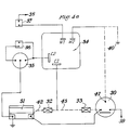
- Figures 4a, 4b illustrate the electrical circuitry associated with said equipment, engine and motor car.
- Figure 1 illustrates, by way of example only, a motor car 100 having a four-cylinder internal combustion engine 101 which is mounted at the front of the car and which is connected by a propeller shaft 102 to final-drive gears, indicated by 103, which transmit the drive to the rear wheels of the car.
- the engine 101 includes a clutch and gearbox and is fed with a fuel stored in an appropriately situated fuel tank. The fuel is burnt after being mixed with air and the heat produced is converted into mechanical power.
- an auxiliary tank 1 for the storage of, for example, one litre of a mineral oil (as defined above); said tank includes a trap section 2 which consists of at least that part of the total volume of the tank 1 which is above the maximum permitted level of the mineral oil therein.
- Said auxiliary tank 1 is placed in any convenient location on the vehicle and is connected by suitable pipework 11 to the lower end of a heat exchanger which comprises two separate electrical heating elements 3 around which extend the convolutions of a helically wound brass tube 9.
- the upper end of the heat exchanger is connected to the trap 2 by way of pipework 91 and said trap is connected to the cylinders (not illustrated) of the engine 101 by way of pipework 21 whose other end is connected to an intermediate element which may be, for example, a carburettor in a spark-ignition internal combustion engine. If the engine is of said spark-ignition type, said other end of the pipework 21 could be connected to the air intake of said carburettor by way of the usual air filter (not illustrated). Alternatively, if the engine is of the Diesel or compression-ignition type, the intermediate element may be an air intake device (for example, the inlet manifold of the engine).
- the auxiliary tank 1 is provided with a convenient filler 4 whose openable end determines the maximum permitted level (referred to above) of the liquid mineral oil and which, as a consequence, ensures that there is always a space above said oil, said space acting as the trap 2.
- the equipment described above with reference to Figure 2 is provided with a thermostat 6 and a cutout 7.
- the function of the thermostat 6 is to disconnect one of the two heating elements 3 when the temperature at which the mineral oil vaporises is reached.
- the function of the cut-out 7 is to disconnect both of heating elements 3 in the event of the mineral oil falling to a very low level in the tank 1 and/or in the event of the thermostat 6 failing to operate properly.
- the electrical heating elements 3 and the convolutions of the coiled tube 9 are provided with some suitable cover or jacket 8 made of a heatretaining material, and the two heating elements 3 may be, if desired, housed within a protective heatconducting cover 5 (as illustrated).
- the liquid mineral oil (for example, that which is colloquially called paraffin by the purchasing public) moves under the influence of gravity along the pipework 11 to the coiled tube 9 in which said mineral oil is heated by the heat emitted by the heating elements 3 and becomes at least partially vaporised.
- the vaporised paraffin (and any paraffin which may still be in liquid form) passes along the pipework 91 and is fed into the trap 2 in which any paraffin which is still in liquid form drops into the remainder of the liquid in the tank 1 whereas the vaporised paraffin passes out of the trap 2 and through the pipework 21 to the intermediate element to be mixed (a) with the combustible mixturr of vaporised petrol and air in the case of a spark ignition engine, or (b) with air in the case of a compression-ignition engine.
- Brass tube 4.75 mm to 5 mm outside diameter and 1.625 mm wall thickness.
- the length of the brass tube before coiling is about 150 cms.
- Each heating element has a rating of 95 Watts.
- Thermostat. This is set to operate at 95° C.
- a thermostat mounted on the pipework 91 and set to operate at 95° C cut out as soon as the system started to produce mineral oil vapour(s). It seemed sensible, therefore, to ensure that one of the heating elements 3 was disconnected at that temperature. The temperature thereafter rose, using the one remaining heating element, to a maximum of about 160° C. Tests were made in order to find out what would happen if the two heating elements 3 were left in circuit and it was found that the temperature rose to around 460° C; at this elevated temperature, "cracking" of the mineral oil became evident (discoloration of the mineral oil) and also the thermal fuse or cut-out 7 blew.
- the bottom end of the temperature range to which the mineral oil should be heated should be 160°C and the top end thereof 350° C, the optimum temperature being 325° C or thereabouts.
- Figure 4a is a circuit diagram illustrating a starter solenoid 30, a battery 31, fuses 32 and 33, a relay 34, heating elements 35, a thermostat 36 and an over-temperature switch 37.
- the connection 38 is to the dynamo or alternator, and the connection 39 is to the starter.
- a dynamo 38 is connected to main output terminal and the earth return 40 should be used; in the case of an alternator, ACR type, 38 is connected to the "Ind" terminal and the earth return 40 should be used; in the case of an alternator, six diode type, 38 is connected to the ignition supply and the earth return 41 should be used.
- the earth return 40 is the metal of the vehicle whereas 41 is the solenoid operating terminal.
- Figure 4(a) includes alternative connections depending upon the position of the battery; if the battery 3i were to be mounted at the front of the vehicle, the circuit portion 42 would be used whereas the circuit portion 43 would be used if the battery were to be mounted at the rear of the vehicle. Moreover, beeause the operating relay 34 is wired across the charging system, the heating elements 35 (which are the same as the heating elements 3 in figure 2) are only energised when the vehicle engine 101 ( Figure 1) is running.
- the other end of the pipework 21 could be connected at the air-intake of the carburettor, namely, upstream of the jet through which the petrol is supplied to the choke tube or venturi. It is thought that sufficiently good results could be obtained if said pipework were to be connected downstream of said choke tube.
- the other end of the pipework 21 will be connected to each carburettor by means of a T-piece.
- a shut-off valve (not illustrated) could be added to the apparatus shown in Figure 2, for example in the pipework 11.
- Such shut-off valve could be electrically operated or vacuum- operated, for example, and the purpose of providing such shut-off valve would be to prevent the apparatus from continuing to produce mineral oil vapour(s) after the engine has been switched off. It is considered that such a shut-off valve would meet the requirements of any emission- control regulations.
- the auxiliary tank 1 and the heat exchanger are near to one another. It will be apparent to anyone skilled in this art, however, that the tank containing the mineral oil could be placed virtually anywhere on the vehicle and that a pump (not illustrated) could be provided in order to draw said mineral oil from the auxiliary tank and to deliver it to the heat exchanger. In such an arrangement, there could be a trap unit (serving exactly the same purpose as the trap section 2 in Figure 2) adjacent the heat exchanger. The heat exchanger and the trap unit would preferably be located in the engine compartment.
- auxiliary tank 1 of Figure 2 could be connected to the heat exchanger by way of a device similar to or identical with the device 9 disclosed in published United Kingdom Patent Specification No. 1 513 051.
- a flowregulating means could be provided in the pipework 91 or in the pipework 21.
- Brass has been mentioned as the preferred material for the tube 9 in Figure 2. It must be pointed out, however, that other materials may well be suitable because the tubing is not exposed to the heat and corrosive effects of exhaust gases (as was the case in the arrangements disclosed in published United Kingdom Patent Specifications No. 1 513 051 and No. 2 078 297). Other materials which, it is thought, would be suitable as a substitute for brass are, for example, copper, aluminium and stainless steel.
- the mineral oil may be fed (either under the influence of gravity or by a pump) by way of a filter to the heat exchanger.
- two heating elements 3 are used.
- one heating element would (it is thought) suffice if its rating was higher and if the thermostat also had a higher setting in order to control the temperature; in such an arrangement, the thermostat would cut in and out in the manner of the thermostat or equivalent device used, for example, in a domestic electric iron.
- auxiliary tank for the storage of the liquid mineral oil need only be large enough to hold one litre of said oil. This would probably be large enough for many private cars but commercial and heavy goods vehicles could be equipped with larger tanks; an auxiliary tank which would hold 4 litres would give just less than 26,000 kilometres (about 16,000 miles) motoring before it would become necessary to refill it.
- the efficiency, in operation, of a system according to the present invention is greater than that of a system according to said Specification No. 2 078 297B because the temperature needed to vaporize the liquid mineral oil is precisely controlled (the optimum temperature being of the order of 325°C) and because this precise control results in a constant rate of production of the required vapour. Said efficiency is also considered to be likely to be far greater than that proposed by Waschkuttis (Bernardet does not merit any consideration because his adopted technique was far removed from the one practised in the engine according to the present invention) because greedkuttis gave no instructions as to temperature(s) to be used, assuming that Waschkuttis was ever carried into effect.
- the operating relay is wired across the charging system with the result that the heating elements 3 are only energised when the engine is running. This prevents the battery from being discharged by said heating elements drawing the necessary power from the battery alone.
Landscapes
- Engineering & Computer Science (AREA)
- Combustion & Propulsion (AREA)
- Mechanical Engineering (AREA)
- General Engineering & Computer Science (AREA)
- Chemical & Material Sciences (AREA)
- Lubrication Of Internal Combustion Engines (AREA)
- Output Control And Ontrol Of Special Type Engine (AREA)
- Valve Device For Special Equipments (AREA)
- Filling Or Discharging Of Gas Storage Vessels (AREA)
- Feeding And Controlling Fuel (AREA)
- Organic Low-Molecular-Weight Compounds And Preparation Thereof (AREA)
- Combustion Methods Of Internal-Combustion Engines (AREA)
- Acyclic And Carbocyclic Compounds In Medicinal Compositions (AREA)
- Medicines Containing Material From Animals Or Micro-Organisms (AREA)
- Pharmaceuticals Containing Other Organic And Inorganic Compounds (AREA)
- Cylinder Crankcases Of Internal Combustion Engines (AREA)
- Lubrication Details And Ventilation Of Internal Combustion Engines (AREA)
- Valve-Gear Or Valve Arrangements (AREA)
- Lubricants (AREA)
Priority Applications (1)
| Application Number | Priority Date | Filing Date | Title |
|---|---|---|---|
| AT86900613T ATE41814T1 (de) | 1985-01-12 | 1986-01-06 | Zusatzbrennstoffverdampfer fuer brennkraftmaschine. |
Applications Claiming Priority (2)
| Application Number | Priority Date | Filing Date | Title |
|---|---|---|---|
| GB8500884 | 1985-01-12 | ||
| GB8500884A GB2169654B (en) | 1985-01-12 | 1985-01-12 | Internal combustion engines |
Publications (2)
| Publication Number | Publication Date |
|---|---|
| EP0209550A1 EP0209550A1 (en) | 1987-01-28 |
| EP0209550B1 true EP0209550B1 (en) | 1989-03-29 |
Family
ID=10572827
Family Applications (1)
| Application Number | Title | Priority Date | Filing Date |
|---|---|---|---|
| EP86900613A Expired EP0209550B1 (en) | 1985-01-12 | 1986-01-06 | Additional liquid fuel vaporizer for internal combustion engine |
Country Status (16)
| Country | Link |
|---|---|
| US (1) | US4748961A (da) |
| EP (1) | EP0209550B1 (da) |
| JP (1) | JPS62502054A (da) |
| KR (1) | KR870700119A (da) |
| AT (1) | ATE41814T1 (da) |
| AU (1) | AU5304486A (da) |
| BR (1) | BR8604532A (da) |
| CA (1) | CA1274736C (da) |
| DE (2) | DE3690010T1 (da) |
| DK (1) | DK435886D0 (da) |
| ES (1) | ES8702983A1 (da) |
| FI (1) | FI863450A0 (da) |
| GB (1) | GB2169654B (da) |
| HU (1) | HUT42594A (da) |
| NO (1) | NO863420L (da) |
| WO (1) | WO1986004116A1 (da) |
Families Citing this family (10)
| Publication number | Priority date | Publication date | Assignee | Title |
|---|---|---|---|---|
| IE67000B1 (en) * | 1990-09-19 | 1996-02-21 | Wardoken Holdings Limited | Internal combustion engines |
| US5443053A (en) * | 1993-07-27 | 1995-08-22 | Johnson; Jack E. | Fuel heater |
| GB2290348A (en) * | 1994-02-11 | 1995-12-20 | Avonbray Ltd | Engine supplied with vaporised secondary fuel |
| US5596973A (en) * | 1995-06-05 | 1997-01-28 | Grice; Franklin R. | Fuel expander |
| GB9524360D0 (en) * | 1995-11-29 | 1996-01-31 | Multipliers Ltd | Engine modifier |
| US20110265769A1 (en) * | 2010-02-10 | 2011-11-03 | Crowther Russell C | Fuel Warming System |
| US8225772B1 (en) * | 2010-02-10 | 2012-07-24 | Russell C Crowther | Fuel warming device |
| US9468875B2 (en) * | 2014-01-14 | 2016-10-18 | Caterpillar Inc. | Filter system and filtration method for fluid reservoirs |
| US9248390B2 (en) * | 2014-01-14 | 2016-02-02 | Caterpillar Inc. | Filter system and filtration method for fluid reservoirs |
| CN105736194B (zh) * | 2016-03-10 | 2018-08-31 | 山推工程机械股份有限公司 | 一种燃气推土机水循环加热系统及燃气推土机 |
Family Cites Families (14)
| Publication number | Priority date | Publication date | Assignee | Title |
|---|---|---|---|---|
| FR576434A (fr) * | 1924-01-29 | 1924-08-20 | Dispositif applicable aux moteurs à combustion interne permettant d'utiliser pour leur alimentation tous combustibles hydrocarburés y compris les huiles lourdes | |
| GB265186A (en) * | 1926-01-27 | 1928-04-20 | Dmitry Balachowsky | Improved process and apparatus for producing a combustible charge for use in an internal combustion engine |
| GB469826A (en) * | 1936-02-03 | 1937-08-03 | Lucean Arthur Headen | Improvements in vaporisers for internal combustion engines |
| US3851633A (en) * | 1972-10-27 | 1974-12-03 | Gen Motors Corp | Fuel system for an internal combustion engine |
| GB1513051A (en) * | 1976-01-09 | 1978-06-07 | Wilkes J | Spark-ignition internal combustion engines |
| US4213433A (en) * | 1977-10-31 | 1980-07-22 | Day John C | Liquid fuel to gas converter for engines |
| CA1084367A (en) * | 1978-01-18 | 1980-08-26 | Kevin J. Elliott | Fuel heating device for internal combustion engines |
| DE2826976A1 (de) * | 1978-06-20 | 1980-01-03 | Gerhard Waschkuttis | Verfahren und vorrichtung durch verbrennung von gemischen aus mittelschweren kohlenwasserstoffen |
| JPS5843655Y2 (ja) * | 1978-12-25 | 1983-10-03 | 日産自動車株式会社 | 内燃機関の吸気絞り弁装置 |
| US4345141A (en) * | 1979-11-15 | 1982-08-17 | Little William D | Electrical fuel preheater assembly |
| GB2065763A (en) * | 1979-12-11 | 1981-07-01 | Econo Fuel Systems Inc | A hot fuel gas generator |
| GB2078297B (en) * | 1980-06-17 | 1983-09-07 | Wilkes John | Internal combustion engine |
| DE3407629A1 (de) * | 1983-02-28 | 1984-10-11 | Gonzalo Quito Moreano Andrade | Verfahren zum antreiben einer brennkraftmaschine des otto-typs sowie brennkraftmaschine |
| GB2144799A (en) * | 1983-08-02 | 1985-03-13 | Andrade Gonzalo Moreano | Internal-combustion engines |
-
1985
- 1985-01-12 GB GB8500884A patent/GB2169654B/en not_active Expired
-
1986
- 1986-01-06 WO PCT/GB1986/000008 patent/WO1986004116A1/en not_active Ceased
- 1986-01-06 KR KR1019860700555A patent/KR870700119A/ko not_active Ceased
- 1986-01-06 DE DE19863690010 patent/DE3690010T1/de not_active Withdrawn
- 1986-01-06 JP JP61500442A patent/JPS62502054A/ja active Pending
- 1986-01-06 AU AU53044/86A patent/AU5304486A/en not_active Abandoned
- 1986-01-06 AT AT86900613T patent/ATE41814T1/de not_active IP Right Cessation
- 1986-01-06 EP EP86900613A patent/EP0209550B1/en not_active Expired
- 1986-01-06 US US06/902,398 patent/US4748961A/en not_active Expired - Fee Related
- 1986-01-06 HU HU86772A patent/HUT42594A/hu unknown
- 1986-01-06 BR BR8604532A patent/BR8604532A/pt unknown
- 1986-01-06 DE DE8686900613T patent/DE3662614D1/de not_active Expired
- 1986-01-10 CA CA499364A patent/CA1274736C/en not_active Expired - Lifetime
- 1986-01-10 ES ES551402A patent/ES8702983A1/es not_active Expired
- 1986-08-26 NO NO863420A patent/NO863420L/no unknown
- 1986-08-26 FI FI863450A patent/FI863450A0/fi not_active Application Discontinuation
- 1986-09-11 DK DK435886A patent/DK435886D0/da not_active Application Discontinuation
Also Published As
| Publication number | Publication date |
|---|---|
| ES551402A0 (es) | 1987-02-01 |
| GB2169654B (en) | 1989-05-04 |
| FI863450A7 (fi) | 1986-08-26 |
| US4748961A (en) | 1988-06-07 |
| HUT42594A (en) | 1987-07-28 |
| DK435886A (da) | 1986-09-11 |
| DK435886D0 (da) | 1986-09-11 |
| GB2169654A (en) | 1986-07-16 |
| DE3662614D1 (en) | 1989-05-03 |
| FI863450A0 (fi) | 1986-08-26 |
| GB8500884D0 (en) | 1985-02-20 |
| NO863420D0 (no) | 1986-08-26 |
| DE3690010T1 (da) | 1987-03-12 |
| EP0209550A1 (en) | 1987-01-28 |
| CA1274736A (en) | 1990-10-02 |
| WO1986004116A1 (en) | 1986-07-17 |
| AU5304486A (en) | 1986-07-29 |
| ES8702983A1 (es) | 1987-02-01 |
| BR8604532A (pt) | 1987-07-14 |
| JPS62502054A (ja) | 1987-08-13 |
| NO863420L (no) | 1986-08-26 |
| KR870700119A (ko) | 1987-03-14 |
| ATE41814T1 (de) | 1989-04-15 |
| CA1274736C (en) | 1990-10-02 |
Similar Documents
| Publication | Publication Date | Title |
|---|---|---|
| US4640234A (en) | Method of running an internal combustion engine with alternative fuels | |
| US3635200A (en) | Hydrocarbon conversion process and apparatus | |
| US5156114A (en) | Aqueous fuel for internal combustion engine and method of combustion | |
| EP0209550B1 (en) | Additional liquid fuel vaporizer for internal combustion engine | |
| US4147142A (en) | Fuel modification system for internal combustion engines | |
| AU648594B2 (en) | Combustion of liquid fuels | |
| JP3233630B2 (ja) | 内燃機関用水性燃料の燃焼方法及び燃料の使用 | |
| CN107076057A (zh) | 具有可调节的燃料空气比的化油器式发动机 | |
| Davis et al. | The development and performance of a high blend ethanol fueled vehicle | |
| US2163241A (en) | Method and apparatus for utilization of low grade fuel in internal combustion engines | |
| US4395998A (en) | Multi-fuel gasifier system for spark ignition engines | |
| US4168685A (en) | Fuel metering device for internal combustion engines and fuel systems incorporating such device | |
| US4403590A (en) | Engine fuel consumption reduction system | |
| US2695011A (en) | Method of operating compression ignition engines | |
| WO1992007922A1 (en) | Aqueous fuel and combustion method for engines | |
| US1559216A (en) | Internal-combustion engine | |
| Haahtela et al. | Present and future fuels and lubricants in cold climate operation | |
| RU2119086C1 (ru) | Способ этилирования бензина в двигателе внутреннего сгорания и устройство для его осуществления | |
| Earl | Alcohol use in engines | |
| EP0039378A1 (en) | Device for vaporizing diesel oil used as a fuel in a spark ignited internal combustion engine | |
| Bergmann | A Highly Efficient Alcohol Vapor Aspirating Spark–Ignition Engine with Heat Recovery | |
| GB2065763A (en) | A hot fuel gas generator | |
| Charoenphonphanich et al. | Low temperature starting techniques for ethanol engine without secondary fuel tank | |
| Meghare et al. | Experimental Investigation on LPG as Alternative Fuel for Two Wheelers | |
| Hunt | HEAVY-FUEL CARBURETER-TYPE ENGINES FOR VEHICLES |
Legal Events
| Date | Code | Title | Description |
|---|---|---|---|
| PUAI | Public reference made under article 153(3) epc to a published international application that has entered the european phase |
Free format text: ORIGINAL CODE: 0009012 |
|
| 17P | Request for examination filed |
Effective date: 19860823 |
|
| AK | Designated contracting states |
Kind code of ref document: A1 Designated state(s): AT BE CH DE FR IT LI LU NL SE |
|
| 17Q | First examination report despatched |
Effective date: 19870605 |
|
| RAP1 | Party data changed (applicant data changed or rights of an application transferred) |
Owner name: WILKES ECONOMY COMPONENTS LIMITED |
|
| GRAA | (expected) grant |
Free format text: ORIGINAL CODE: 0009210 |
|
| AK | Designated contracting states |
Kind code of ref document: B1 Designated state(s): AT BE CH DE FR IT LI LU NL SE |
|
| REF | Corresponds to: |
Ref document number: 41814 Country of ref document: AT Date of ref document: 19890415 Kind code of ref document: T |
|
| ITF | It: translation for a ep patent filed | ||
| REF | Corresponds to: |
Ref document number: 3662614 Country of ref document: DE Date of ref document: 19890503 |
|
| ET | Fr: translation filed | ||
| PLBE | No opposition filed within time limit |
Free format text: ORIGINAL CODE: 0009261 |
|
| STAA | Information on the status of an ep patent application or granted ep patent |
Free format text: STATUS: NO OPPOSITION FILED WITHIN TIME LIMIT |
|
| 26N | No opposition filed | ||
| PGFP | Annual fee paid to national office [announced via postgrant information from national office to epo] |
Ref country code: LU Payment date: 19910130 Year of fee payment: 6 |
|
| ITTA | It: last paid annual fee | ||
| PGFP | Annual fee paid to national office [announced via postgrant information from national office to epo] |
Ref country code: NL Payment date: 19910131 Year of fee payment: 6 Ref country code: FR Payment date: 19910131 Year of fee payment: 6 |
|
| PGFP | Annual fee paid to national office [announced via postgrant information from national office to epo] |
Ref country code: CH Payment date: 19910201 Year of fee payment: 6 |
|
| PGFP | Annual fee paid to national office [announced via postgrant information from national office to epo] |
Ref country code: BE Payment date: 19910207 Year of fee payment: 6 |
|
| PGFP | Annual fee paid to national office [announced via postgrant information from national office to epo] |
Ref country code: SE Payment date: 19910318 Year of fee payment: 6 |
|
| PGFP | Annual fee paid to national office [announced via postgrant information from national office to epo] |
Ref country code: AT Payment date: 19910328 Year of fee payment: 6 |
|
| EPTA | Lu: last paid annual fee | ||
| PG25 | Lapsed in a contracting state [announced via postgrant information from national office to epo] |
Ref country code: LU Free format text: LAPSE BECAUSE OF NON-PAYMENT OF DUE FEES Effective date: 19920106 Ref country code: AT Effective date: 19920106 |
|
| PG25 | Lapsed in a contracting state [announced via postgrant information from national office to epo] |
Ref country code: SE Effective date: 19920107 |
|
| PG25 | Lapsed in a contracting state [announced via postgrant information from national office to epo] |
Ref country code: LI Effective date: 19920131 Ref country code: CH Effective date: 19920131 Ref country code: BE Effective date: 19920131 |
|
| BERE | Be: lapsed |
Owner name: WILKES ECONOMY COMPONENTS LTD Effective date: 19920131 |
|
| PG25 | Lapsed in a contracting state [announced via postgrant information from national office to epo] |
Ref country code: NL Effective date: 19920801 |
|
| NLV4 | Nl: lapsed or anulled due to non-payment of the annual fee | ||
| PG25 | Lapsed in a contracting state [announced via postgrant information from national office to epo] |
Ref country code: FR Effective date: 19920930 |
|
| PGFP | Annual fee paid to national office [announced via postgrant information from national office to epo] |
Ref country code: DE Payment date: 19920930 Year of fee payment: 7 |
|
| REG | Reference to a national code |
Ref country code: CH Ref legal event code: PL |
|
| REG | Reference to a national code |
Ref country code: FR Ref legal event code: ST |
|
| PG25 | Lapsed in a contracting state [announced via postgrant information from national office to epo] |
Ref country code: DE Effective date: 19931001 |
|
| EUG | Se: european patent has lapsed |
Ref document number: 86900613.0 Effective date: 19920806 |
|
| PG25 | Lapsed in a contracting state [announced via postgrant information from national office to epo] |
Ref country code: IT Free format text: LAPSE BECAUSE OF NON-PAYMENT OF DUE FEES;WARNING: LAPSES OF ITALIAN PATENTS WITH EFFECTIVE DATE BEFORE 2007 MAY HAVE OCCURRED AT ANY TIME BEFORE 2007. THE CORRECT EFFECTIVE DATE MAY BE DIFFERENT FROM THE ONE RECORDED. Effective date: 20050106 |