EP0209484A2 - Dispositif antidérapant pour véhicules automobiles - Google Patents
Dispositif antidérapant pour véhicules automobiles Download PDFInfo
- Publication number
- EP0209484A2 EP0209484A2 EP86730113A EP86730113A EP0209484A2 EP 0209484 A2 EP0209484 A2 EP 0209484A2 EP 86730113 A EP86730113 A EP 86730113A EP 86730113 A EP86730113 A EP 86730113A EP 0209484 A2 EP0209484 A2 EP 0209484A2
- Authority
- EP
- European Patent Office
- Prior art keywords
- holder
- compression springs
- sleeves
- chain
- connecting elements
- Prior art date
- Legal status (The legal status is an assumption and is not a legal conclusion. Google has not performed a legal analysis and makes no representation as to the accuracy of the status listed.)
- Granted
Links
Images

Classifications
-
- B—PERFORMING OPERATIONS; TRANSPORTING
- B60—VEHICLES IN GENERAL
- B60B—VEHICLE WHEELS; CASTORS; AXLES FOR WHEELS OR CASTORS; INCREASING WHEEL ADHESION
- B60B39/00—Increasing wheel adhesion
- B60B39/003—Vehicle mounted non-skid chains actuated by centrifugal force
Definitions
- the invention relates to an anti-skid device for motor vehicles with a plurality of elastic spreader arms distributed over the circumference of a holder that can be pressed against the tire of a vehicle and set into a circular movement, to which chain strands forming anti-slip agents are connected, the ends of which, facing away from the spreader arms, with the holder rotating around in the operating position Centrifugal force are thrown away from the holder and at least parts of which pass the area of the tire contact surface when the vehicle tire rotates.
- an anti-skid device of the above type in which the spreader arms are designed as rope or chain strand sections firmly enclosed by rubber sheathing.
- the rubber sheaths have at one end a head provided with an annular groove, which together with a locking ring serves to anchor the spreader arms on the holder and whose resilient properties are intended to make it easy to replace the spreader arms and the chain strands held by them.
- the known solution is unsatisfactory because the strength of the anchoring of the spreader arms and the chain strands connected to them leave something to be desired. Apart from this, the vulcanization process, which is inevitable in the known construction, adversely affects the manufacturing costs of the spreading arms.
- the aim of the spreading arms is to transfer the chain strands that form the anti-slip agents into a favorable position relative to the tire rolling surface or the wedge gap between vehicle tires and the road.
- an entanglement of the chain strands should be counteracted.
- the same purpose is used in a known from US-PS 30 68 949 anti-skid device between the anti-skid elements and the holder tension springs, one end of which has an eyelet for fastening the springs to the screw bolts.
- the tension springs in view of the fact that they have to transmit high centrifugal forces, must have considerable cross-sections of the windings, which place narrow limits on their flexibility.
- considerable changing forces occur in the area of the transition between the fastening eyelet and the main part of the spring, which entail the risk of premature fatigue breaks.
- FR-PS 409 240 shows a non-slip device in which chain strands forming anti-slip agents are connected via springs to a holder.
- the holder cannot be pressed against the vehicle tire and the springs serving to drive it are likewise exposed to not insignificant tensile forces .
- the invention has for its object to provide an anti-skid device of the type under consideration, which can be manufactured inexpensively, ensures a secure mounting of the chain strands forming the anti-skid means on the holder and in which the spreading arms quickly and without large swinging movements in their. Move back to the starting position.
- This object is achieved in that the spreading arms are formed by compression springs which are biased by connecting elements which connect the chain strands to the holder.
- the anti-skid device offers the distribution that, due to the use of prestressed compression springs as spreading arms, the entry and exit of the anti-slip agents into and out of the area of the floor rolling surface of the tire is significantly improved, a whip effect of the spreading arms occurring in the known constructions being avoided .
- the fact that the chain strands forming the anti-slip agents are connected to the holder via connecting elements and not via the spreading arms ensures that they are properly and securely anchored to the holder.
- the compression springs are most deformed during use in the area of their holder-side ends.
- the connecting elements are formed by chain strand sections, there may be contact between the connecting elements and the compression springs, which promote signs of wear on the compression springs.
- a further embodiment of the invention is in the field the ends of the compression springs facing the holder are arranged between the connecting elements and the compression spring sleeves. In this way, the service life of the compression springs and thus the anti-skid device can be increased overall.
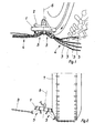
- Fig. 1 is the friction wheel holder of an anti-skid device which is attached to a cantilever arm 2.
- the holder 1 is evenly above its six Scope distributed chain chain groups 4 consisting of four chain strands 3, of which only two have been shown to increase clarity.
- the individual chain strand groups 4 are connected to the holder 1 via elastic spreading arms 5.
- the axis of rotation 6 of the holder 1 is inclined to the roadway and the spreader arms 5, to which only one chain strand is connected in the case of Fig. 2, are in turn inclined to the axis of rotation 6, so that they are inclined to Rolling surface of the tire 7 run.
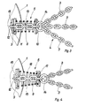
- the spreading arm 5 is formed by a cylindrical compression spring 8 which is arranged between two abutments 9 and 10.
- the abutment 9 is fixedly connected to the holder and forms a support surface 11, which extends obliquely to the underside of the holder, for one end of the compression spring 8.
- the end link of a chain strand section 13 projects through a recess 12 in the abutment Ring 14 connects to a chain strand group 4 combined chain strands 3 with the holder 1.
- the end member is secured to the holder 1 by a locking member 15.
- the ring 14 forms a stop for the abutment 10.
- the distance between the abutments 9 and 10 is chosen so that the compression spring 8 is acted upon with a sufficient preload, although care must be taken to ensure that the turns of the spring 8 do not touch In the manner described it is achieved that the spreading arm is sufficiently flexible on the one hand, but on the other hand does not tend to undesirably strong oscillating movements. It proves to be advantageous that the compression spring 8 can be used at the same time for locking the locking member 15.
- the spreader arm according to FIG. 4 largely corresponds to the spreader arm according to FIG. 3.
- the same reference numerals were therefore used for corresponding parts, so that only the differences between the two constructions need to be pointed out here.
- the compression spring 16 forming the expansion arm 5 according to FIG. 4 is conical.
- the abutment 17 facing away from the holder 1 has the shape of a cap which guides the free spring end.
- In-Fig. 5 is 1 a holder, on the underside of which a disk-shaped stamped part 18 is screwed and which is used to hold chain strands 3, which are again combined into groups or bundles 4.
- a disk-shaped stamped part 18 is screwed and which is used to hold chain strands 3, which are again combined into groups or bundles 4.
- six chain strand bundles are evenly distributed over the circumference of the holder.
- Spreading arms 5 are anchored to the holder by a transverse chain link 19 each.
- the sleeves 20 form centerings for compression springs 16, which are arranged between two abutments 9 and 17, the abutments 9 being formed by bent tongues of the stamped part 18.
- the chain link 22 is used, which is guided in a recess 12 of the abutment 9.
- 13 is a connecting element designed as a chain strand section, which connects the chain strands 3 to the holder.
- a ring 14 is arranged, which combines the chain strands 3 to form a chain strand group.
- the compression spring 16 is conical, as in the case of FIG. 4, at least over part of its length. Your free end can also be cylindrical.
- the spreading arms 5 are deformed during use of the anti-skid device. The greatest deformation takes place in the area of the chain link 23 of the chain strand sections B forming the connecting element 13.
- the sleeve 20 prevents wear-promoting friction contacts between the chain link 23 and the turns of the compression spring 16 located in the vicinity thereof. For this purpose, the sleeves 20 protrude into the compression springs 16 by an amount which corresponds to the height of two to three spring windings.
- the sleeve 20 is cylindrical.
- a sleeve 24 with a conical outer wall is shown in FIG. 6.
- an anti-wear ring 25 which is made of a suitable material, in particular a plastic such as nylon or Teflon. In both cases shown, the sleeves 20 and 24 are held in their desired position due to the conicity of the compression springs 16.
Landscapes
- Engineering & Computer Science (AREA)
- Mechanical Engineering (AREA)
- Devices For Conveying Motion By Means Of Endless Flexible Members (AREA)
- Springs (AREA)
Priority Applications (1)
| Application Number | Priority Date | Filing Date | Title |
|---|---|---|---|
| AT86730113T ATE54618T1 (de) | 1985-07-19 | 1986-07-17 | Gleitschutzvorrichtung fuer kraftfahrzeuge. |
Applications Claiming Priority (4)
| Application Number | Priority Date | Filing Date | Title |
|---|---|---|---|
| DE19853526359 DE3526359A1 (de) | 1985-07-19 | 1985-07-19 | Gleitschutzvorrichtung fuer kraftfahrzeuge |
| DE3526359 | 1985-07-19 | ||
| DE3532801 | 1985-09-11 | ||
| DE19853532801 DE3532801A1 (de) | 1985-09-11 | 1985-09-11 | Gleitschutzvorrichtung fuer kraftfahrzeuge |
Publications (3)
| Publication Number | Publication Date |
|---|---|
| EP0209484A2 true EP0209484A2 (fr) | 1987-01-21 |
| EP0209484A3 EP0209484A3 (en) | 1987-12-16 |
| EP0209484B1 EP0209484B1 (fr) | 1990-07-18 |
Family
ID=25834289
Family Applications (1)
| Application Number | Title | Priority Date | Filing Date |
|---|---|---|---|
| EP86730113A Expired - Lifetime EP0209484B1 (fr) | 1985-07-19 | 1986-07-17 | Dispositif antidérapant pour véhicules automobiles |
Country Status (3)
| Country | Link |
|---|---|
| US (1) | US4751975A (fr) |
| EP (1) | EP0209484B1 (fr) |
| DE (1) | DE3672706D1 (fr) |
Cited By (1)
| Publication number | Priority date | Publication date | Assignee | Title |
|---|---|---|---|---|
| WO1994005519A1 (fr) * | 1992-09-02 | 1994-03-17 | Rud-Kettenfabrik Rieger & Dietz Gmbh. U. Co. | Dispositif antiderapant pour automobiles |
Families Citing this family (9)
| Publication number | Priority date | Publication date | Assignee | Title |
|---|---|---|---|---|
| DE68906065D1 (de) * | 1988-03-25 | 1993-05-27 | Beka St Aubin Sa | Vorrichtung zum ein- und feststellen einer hilfs-gleitschutzkette fuer kraftfahrzeuge. |
| CH676828A5 (fr) * | 1988-07-13 | 1991-03-15 | Autotyp Sa | |
| DE3826775A1 (de) * | 1988-08-06 | 1990-02-08 | Bosch Gmbh Robert | Verfahren und vorrichtung zur verbesserung von traktion und fahrstabilitaet bei fahrzeugen |
| USD364173S (en) | 1994-03-14 | 1995-11-14 | Wylie Woods | Vehicle mounted sand dispenser |
| US7766387B1 (en) * | 2007-08-02 | 2010-08-03 | Onspot Of North America, Inc. | Anti-skid tire chain device |
| US20110146866A1 (en) * | 2009-12-19 | 2011-06-23 | Samad Jafari Valilou | Automatic tire chain system |
| KR100988373B1 (ko) | 2010-05-07 | 2010-10-18 | 신용균 | 차량용 스노우체인 자동설치 장치 |
| KR101098645B1 (ko) | 2011-07-26 | 2011-12-23 | 김래한 | 차량의 설빙 주행용 안전장치 |
| US10675914B2 (en) * | 2017-12-20 | 2020-06-09 | Dusawn Holdings LLC | Tire chains apparatus |
Citations (3)
| Publication number | Priority date | Publication date | Assignee | Title |
|---|---|---|---|---|
| FR409240A (fr) | 1909-10-12 | 1910-04-16 | Hippolyte Rogier | Bouche d'égout inodore, à syphon automatique, pour rue inclinée ou horizontale |
| US3068949A (en) | 1959-10-19 | 1962-12-18 | Rosaire J Sirois | Traction arm for vehicle anti-skid device |
| DE2914366A1 (de) | 1978-04-10 | 1979-10-18 | Goeran Toernebaeck | Gleitschutz fuer kraftfahrzeuge |
Family Cites Families (8)
| Publication number | Priority date | Publication date | Assignee | Title |
|---|---|---|---|---|
| US1150148A (en) * | 1912-10-03 | 1915-08-17 | William H Putnam | Traction and antiskidding device. |
| GB159605A (en) * | 1919-12-01 | 1921-03-01 | Edmund Haselden Bramall | Improvements in or relating to non-skid devices for motor and other vehicles |
| US1374252A (en) * | 1919-12-19 | 1921-04-12 | Thorne | Antiskid device for automobiles, &c. |
| US2241923A (en) * | 1940-02-02 | 1941-05-13 | Herbert N Ridgway | Automatic emergency traction device for automobiles |
| US2283948A (en) * | 1941-04-09 | 1942-05-26 | Herbert N Ridgway | Automobile traction device |
| US2815828A (en) * | 1955-09-16 | 1957-12-10 | John H Schaefer | Automatic traction device for automobiles |
| DE3433620C2 (de) * | 1984-09-10 | 1986-11-20 | Rud-Kettenfabrik Rieger & Dietz Gmbh U. Co, 7080 Aalen | Gleitschutzvorrichtung |
| DE8526271U1 (de) * | 1985-09-11 | 1985-11-14 | Rud-Kettenfabrik Rieger & Dietz Gmbh U. Co, 7080 Aalen | Gleitschutzvorrichtung für Kraftfahrzeuge |
-
1986
- 1986-07-17 EP EP86730113A patent/EP0209484B1/fr not_active Expired - Lifetime
- 1986-07-17 DE DE8686730113T patent/DE3672706D1/de not_active Expired - Lifetime
- 1986-07-18 US US06/887,907 patent/US4751975A/en not_active Expired - Fee Related
Patent Citations (3)
| Publication number | Priority date | Publication date | Assignee | Title |
|---|---|---|---|---|
| FR409240A (fr) | 1909-10-12 | 1910-04-16 | Hippolyte Rogier | Bouche d'égout inodore, à syphon automatique, pour rue inclinée ou horizontale |
| US3068949A (en) | 1959-10-19 | 1962-12-18 | Rosaire J Sirois | Traction arm for vehicle anti-skid device |
| DE2914366A1 (de) | 1978-04-10 | 1979-10-18 | Goeran Toernebaeck | Gleitschutz fuer kraftfahrzeuge |
Cited By (1)
| Publication number | Priority date | Publication date | Assignee | Title |
|---|---|---|---|---|
| WO1994005519A1 (fr) * | 1992-09-02 | 1994-03-17 | Rud-Kettenfabrik Rieger & Dietz Gmbh. U. Co. | Dispositif antiderapant pour automobiles |
Also Published As
| Publication number | Publication date |
|---|---|
| EP0209484B1 (fr) | 1990-07-18 |
| US4751975A (en) | 1988-06-21 |
| EP0209484A3 (en) | 1987-12-16 |
| DE3672706D1 (de) | 1990-08-23 |
Similar Documents
| Publication | Publication Date | Title |
|---|---|---|
| EP0210362B1 (fr) | Crampon pour chaussure de sport | |
| DE102009042720A1 (de) | Gleitschutzstift | |
| EP0209484B1 (fr) | Dispositif antidérapant pour véhicules automobiles | |
| EP0298906B2 (fr) | Dispositif antidérapant pour roues de véhicules | |
| EP0211798B1 (fr) | Dispositif antidérapant pour véhicules automobiles | |
| DE69201525T2 (de) | Gleitschutzvorrichtung für Kraftfahrzeugreifen. | |
| DE1021212B (de) | Elastische Mitnehmerscheibe fuer Gelenkkupplungen | |
| DE2708538B2 (de) | Verbindung zwischen den Kettengliedern einer Gleiskette | |
| DE3526359C2 (fr) | ||
| DE2322253A1 (de) | Gelenk-kupplung fuer gestaenge | |
| DE8414654U1 (de) | Drehsteife, beugeelastische wellenkupplung | |
| DE3047160C2 (fr) | ||
| DE8521267U1 (de) | Gleitschutzvorrichtung für Kraftfahrzeuge | |
| DE2914127B1 (de) | Kettenrad,insbesondere Antriebsrad fuer Gleiskettenfahrzeuge | |
| EP3461712B1 (fr) | Marchepied pour véhicules | |
| EP3582975B1 (fr) | Roue ferroviaire et corps élastique pour une telle roue ferroviaire | |
| EP0658448A1 (fr) | Elément pour roues ferroviaires élastiques et roue ferroviaire élastique avec caoutchouc | |
| EP0183641A2 (fr) | Maillon de raccordement | |
| DE8526271U1 (de) | Gleitschutzvorrichtung für Kraftfahrzeuge | |
| DE3532801A1 (de) | Gleitschutzvorrichtung fuer kraftfahrzeuge | |
| EP0278101A1 (fr) | Machine de fenaison | |
| EP2354073A1 (fr) | Dispositif de fixation d'un élément de suspension pour une installation d'ascenseur | |
| AT375743B (de) | Gummiteil zur uebertragung von kraeften | |
| EP2206616B1 (fr) | Support d'élément antidérapant | |
| EP0467494A1 (fr) | Dispositif antidérapant pour véhicules automobiles |
Legal Events
| Date | Code | Title | Description |
|---|---|---|---|
| PUAI | Public reference made under article 153(3) epc to a published international application that has entered the european phase |
Free format text: ORIGINAL CODE: 0009012 |
|
| AK | Designated contracting states |
Kind code of ref document: A2 Designated state(s): AT BE CH DE FR GB IT LI NL SE |
|
| PUAL | Search report despatched |
Free format text: ORIGINAL CODE: 0009013 |
|
| AK | Designated contracting states |
Kind code of ref document: A3 Designated state(s): AT BE CH DE FR GB IT LI NL SE |
|
| 17P | Request for examination filed |
Effective date: 19880428 |
|
| 17Q | First examination report despatched |
Effective date: 19880908 |
|
| GRAA | (expected) grant |
Free format text: ORIGINAL CODE: 0009210 |
|
| AK | Designated contracting states |
Kind code of ref document: B1 Designated state(s): AT BE CH DE FR GB IT LI NL SE |
|
| REF | Corresponds to: |
Ref document number: 54618 Country of ref document: AT Date of ref document: 19900815 Kind code of ref document: T |
|
| REF | Corresponds to: |
Ref document number: 3672706 Country of ref document: DE Date of ref document: 19900823 |
|
| ET | Fr: translation filed | ||
| ITF | It: translation for a ep patent filed | ||
| GBT | Gb: translation of ep patent filed (gb section 77(6)(a)/1977) | ||
| PLBE | No opposition filed within time limit |
Free format text: ORIGINAL CODE: 0009261 |
|
| STAA | Information on the status of an ep patent application or granted ep patent |
Free format text: STATUS: NO OPPOSITION FILED WITHIN TIME LIMIT |
|
| 26N | No opposition filed | ||
| ITTA | It: last paid annual fee | ||
| PGFP | Annual fee paid to national office [announced via postgrant information from national office to epo] |
Ref country code: GB Payment date: 19920715 Year of fee payment: 7 |
|
| PGFP | Annual fee paid to national office [announced via postgrant information from national office to epo] |
Ref country code: FR Payment date: 19920716 Year of fee payment: 7 |
|
| PGFP | Annual fee paid to national office [announced via postgrant information from national office to epo] |
Ref country code: NL Payment date: 19920731 Year of fee payment: 7 |
|
| PGFP | Annual fee paid to national office [announced via postgrant information from national office to epo] |
Ref country code: BE Payment date: 19920807 Year of fee payment: 7 |
|
| PG25 | Lapsed in a contracting state [announced via postgrant information from national office to epo] |
Ref country code: GB Effective date: 19930717 |
|
| PG25 | Lapsed in a contracting state [announced via postgrant information from national office to epo] |
Ref country code: BE Effective date: 19930731 |
|
| BERE | Be: lapsed |
Owner name: RUD-KETTENFABRIK RIEGER & DIETZ G.M.B.H. U. CO. Effective date: 19930731 |
|
| PG25 | Lapsed in a contracting state [announced via postgrant information from national office to epo] |
Ref country code: NL Effective date: 19940201 |
|
| GBPC | Gb: european patent ceased through non-payment of renewal fee |
Effective date: 19930717 |
|
| NLV4 | Nl: lapsed or anulled due to non-payment of the annual fee | ||
| PG25 | Lapsed in a contracting state [announced via postgrant information from national office to epo] |
Ref country code: FR Effective date: 19940331 |
|
| REG | Reference to a national code |
Ref country code: FR Ref legal event code: ST |
|
| PGFP | Annual fee paid to national office [announced via postgrant information from national office to epo] |
Ref country code: AT Payment date: 19940721 Year of fee payment: 9 |
|
| PGFP | Annual fee paid to national office [announced via postgrant information from national office to epo] |
Ref country code: SE Payment date: 19940731 Year of fee payment: 9 |
|
| PGFP | Annual fee paid to national office [announced via postgrant information from national office to epo] |
Ref country code: CH Payment date: 19940819 Year of fee payment: 9 |
|
| PGFP | Annual fee paid to national office [announced via postgrant information from national office to epo] |
Ref country code: DE Payment date: 19940826 Year of fee payment: 9 |
|
| EAL | Se: european patent in force in sweden |
Ref document number: 86730113.7 |
|
| PG25 | Lapsed in a contracting state [announced via postgrant information from national office to epo] |
Ref country code: AT Effective date: 19950717 |
|
| PG25 | Lapsed in a contracting state [announced via postgrant information from national office to epo] |
Ref country code: SE Effective date: 19950718 |
|
| PG25 | Lapsed in a contracting state [announced via postgrant information from national office to epo] |
Ref country code: LI Effective date: 19950731 Ref country code: CH Effective date: 19950731 |
|
| REG | Reference to a national code |
Ref country code: CH Ref legal event code: PL |
|
| PG25 | Lapsed in a contracting state [announced via postgrant information from national office to epo] |
Ref country code: DE Effective date: 19960402 |
|
| EUG | Se: european patent has lapsed |
Ref document number: 86730113.7 |
|
| PG25 | Lapsed in a contracting state [announced via postgrant information from national office to epo] |
Ref country code: IT Free format text: LAPSE BECAUSE OF NON-PAYMENT OF DUE FEES;WARNING: LAPSES OF ITALIAN PATENTS WITH EFFECTIVE DATE BEFORE 2007 MAY HAVE OCCURRED AT ANY TIME BEFORE 2007. THE CORRECT EFFECTIVE DATE MAY BE DIFFERENT FROM THE ONE RECORDED. Effective date: 20050717 |