EP0208480A2 - Detonator actuator - Google Patents
Detonator actuator Download PDFInfo
- Publication number
- EP0208480A2 EP0208480A2 EP86304991A EP86304991A EP0208480A2 EP 0208480 A2 EP0208480 A2 EP 0208480A2 EP 86304991 A EP86304991 A EP 86304991A EP 86304991 A EP86304991 A EP 86304991A EP 0208480 A2 EP0208480 A2 EP 0208480A2
- Authority
- EP
- European Patent Office
- Prior art keywords
- actuate
- actuator
- detonator
- arm
- signal
- Prior art date
- Legal status (The legal status is an assumption and is not a legal conclusion. Google has not performed a legal analysis and makes no representation as to the accuracy of the status listed.)
- Granted
Links
Images









Classifications
-
- F—MECHANICAL ENGINEERING; LIGHTING; HEATING; WEAPONS; BLASTING
- F42—AMMUNITION; BLASTING
- F42B—EXPLOSIVE CHARGES, e.g. FOR BLASTING, FIREWORKS, AMMUNITION
- F42B3/00—Blasting cartridges, i.e. case and explosive
- F42B3/10—Initiators therefor
- F42B3/12—Bridge initiators
- F42B3/121—Initiators with incorporated integrated circuit
- F42B3/122—Programmable electronic delay initiators
-
- F—MECHANICAL ENGINEERING; LIGHTING; HEATING; WEAPONS; BLASTING
- F42—AMMUNITION; BLASTING
- F42C—AMMUNITION FUZES; ARMING OR SAFETY MEANS THEREFOR
- F42C15/00—Arming-means in fuzes; Safety means for preventing premature detonation of fuzes or charges
- F42C15/40—Arming-means in fuzes; Safety means for preventing premature detonation of fuzes or charges wherein the safety or arming action is effected electrically
-
- F—MECHANICAL ENGINEERING; LIGHTING; HEATING; WEAPONS; BLASTING
- F42—AMMUNITION; BLASTING
- F42D—BLASTING
- F42D1/00—Blasting methods or apparatus, e.g. loading or tamping
- F42D1/04—Arrangements for ignition
- F42D1/045—Arrangements for electric ignition
- F42D1/05—Electric circuits for blasting
- F42D1/055—Electric circuits for blasting specially adapted for firing multiple charges with a time delay
Definitions
- This invention relates to an actuator to be used with a detonator and to a detonator-actuating system for use in blasting.
- a conventional blasting system comprises a series of explosive charges which are detonated by detonators which are wired to a remote command source.
- the detonators are provided with delays, such that the last detonator to explode has received its firing signal prior to the explosion of the first.
- Recent improvements in the system have included electronic delays (replacing the older, less precise pyrotechnic delays), and the ability to program such delays in situ.
- German Offenlegungsschrift 3301251 provides an example of the versatility of which these systems are capable.
- detonator which comprises conditioning means which renders fusehead conductors incapable of carrying a voltage or current capable of firing the detonator prior to the altering of the conditioning means from a "normal" (incapable of being fired) state to an "armed” state. This provides a considerable safety factor not previously present in detonators.
- an actuator for a detonator characterised in that the actuator comprises control circuitry which is responsive to input signals from the control device applied to inputs thereof, said control circuitry being operable, on receipt of at least one predetermined input signal, to (i) generate an output arm signal which is applied in use to the detonator and render it capable of being acutated and (ii) generate an output actuate signal which is applied to the detonator after a predetermined delay relative to said predetermined input signals to cause explosive actuation of the detonator.
- actuator I mean a unit whose function is to receive signals from a control device, and to actuate a detonator.
- the type of detonator with which an actuator of the type used in this invention is associated may be one which must be armed before it can be detonated. An especially preferred type is described in my co-pending Australian Patent Application No. PH1255.
- the actuators according to my invention may be used in association with conventional detonators by, for example, connecting the detonator with the actuator such that only the actuate signal is transmitted to the detonator.
- associated I mean that the detonator and the actuator may be connected in some way such that signals may be passed from actuator to detonator.
- the actuator for use in this invention incorporates the delay which is so important in large- scale commercial blasting.
- the specific length of delay may be built into the actuator during manufacture, but I prefer to have the delay programmable; this confers considerable versatility on the system.
- an actuator may be programmed electronically prior to its being inserted in a blasthole. Even more versatility is conferred by having the actuator programmable when the detonator is in place in the blasthole via the means through which the input signals are transmitted. Thus, a blast pattern can be altered at will and in complete safety up to the time of sending of the input arm and input actuate signals.
- the electronic circuitry within the actuator stores delay information and acts on an appropriate signal or appropriate signals from the control device to generate output arm and output actuate signals separated by a selected delay time.
- the circuitry will comprise a microcomputer with a memory which stores at least both an arm code and an actuate code and preferably also the selected delay time.
- the microcomputer analyses input signals, and when it identifies a predetermined signal or pre- determined signals it then causes to be generated appropriate corresponding output arm and actuate signals.
- the nature of the signal received by the actuator may be any suitable signal known to the art. It may be, for example, a single signal, and the circuitry of the actuator may be such that this signal can cause the generation, by reference to the arm and actuate codes and the predetermined delay stored in the actuator circuitry, of both arm and actuate signals, separated by a predetermined delay.
- a typical signal of this type is a voltage which is in excess of a predetermined level.
- Other signals may comprise both an arm code and an actuate code, for example, a voltage step signal wherein the leading edge of the signal comprises an arm signal and the trailing edge an actuate signal. I prefer, however, that both arm and actuate signals be digital signals. This has a number of advantages. It means that if the actuator is conditioned to recognise certain digital codes, it will act only on those codes. Accidental or unauthorised firing can thus be almost completely eliminated.
- the nature of the signal or signals transmitted by the actuator to the detonator may be any convenient signal suitable for the purposes of actuating the detonator.
- a conventional detonator it may be a simple voltage or current suitable for causing the ignition of a flashing mixture and the consequent explosion of the detonator.
- the signal preferably comprises multi-bit digital code; when such a signalling system is used with a preferred detonator as described in my co-pending Australian Patent Application No. PH 1255, it permits of degrees of security and safety not attainable with known detonating systems.
- the power to drive the actuator and the detonator itself may be provided by any convenient means, consistent with the fact that a detonator set to explode late in a series of blasts should not be prone to failure by the breakage by an earlier explosion of a wire connection thereto.
- the power source for the arming and actuating of the detonator should therefore be in close proximity to the actuator and preferably either enclosed within the actuator housing or capable of being connected to it.
- the power source may be a battery, or preferably a temporary power source such as a capacitor which is charged by signals from the surface.
- the capacitor is housed in a separate modular unit which can be attached to the detonator and actuator units, such that they form an integral unit with internal wiring and connections appropriately joined by the act of joining together the individual modular units.
- the actuator receives its signals from a control device on the surface.
- This may be a remote exploder box of the type well known to the art.
- the actuators of my invention are used in conjunction with a selected control device, the result is a detonator actuating system of remarkable versatility and safety. I therefore also provide a detonator actuating system comprising
- My invention additionally provides a control device suitable for use in a detonator actuating system as hereinabove described, and a method of blasting using such a system.
- the control device which acts in concert with the actuator is adapted to control a plurality of detonators. It comprises a microcomputer with at least arm and actuate codes, and arm and actuate keys which, when operated, act to generate arm and actuate signals and send them to the actuator.
- the microcomputer is such that the actuator key must be operated within a predetermined period after operation of the arm key, otherwise no actuate signal is transmitted. This feature adds a further useful margin of safety to an already very safe system.
- the memory additionally stores a reset code and the microcomputer operates to generate an output reset signal derived from the reset code if the actuate key is not actuated within the predetermined period after actuation of-the arm key, the output reset signal rendering the detonators incapable of being explosively actuated until a predetermined sequence of output arm and actuate signals is received.
- the actuator must have appropriate circuitry which permits of this resetting function.
- the delay of the actuator unit may be calibrated from the control device. This may be achieved by having an actuator unit which is responsive to calibrate signals and the microcomputer of the control device is arranged to generate an output calibrate signal in response to actuation of a calibrate key or a programmed instruction whereupon timing means in the control circuitry of the actuator unit is actuated for a period terminated by a control signal from the control device, the output of the timing means being stored in the control circuitry whereby a delay period stored therein can be calibrated on a time basis relative to the control device. It is possible to incorporate the calibration function in the control device such that it is automatically carried out when the arm key is operated.
- the actuator may be equipped with a transducer unit which is couplable thereto such that all the appropriate electrical connections are made by the coupling.
- a transducer is an electronic device which is responsive to a preselected physical parameter (for example, pressure or temperature) and which produces corresponding condition signals which may then be sent, for example, to a measuring instrument or to an apparatus affected by the parameter so as to modify its behaviour.
- information from a transducer may be used to vary the calibration of the actuator, and any variation is communicated back to the control device at the surface, which control device is capable of receiving such signals.
- the actuator can thus "talk back" to the control device and this permits much tighter control over blasting operations.
- the control device may include a connector which enables direct connection with the control circuitry of the actuator units so as to read data stored in the actuator unit. That data might for instance comprise an identity code of the user, a code number assigned to a particular blast, and the delay period programmed into the detonator control circuitry.
- the control device may include a display such as an LCD display or a VDU for displaying this information to the user.
- the detonators may be receptive to control signals which prevent them from operating, and the control device may comprise circuitry which sends to the detonators a continuous stream of control signals which prevents any accidental or inadvertent firing. Suitable circuitry is described in my co-pending Australian Patent Application No. PH1258.
- the detor.ator unit 22 comprises a tubular housing 44 which for instance might be formed from aluminium, or a resilient material which is a conductor such as ) carbonised rubber.
- the housing 44 is provided with transverse partitions 46 and 48 press fit into the housing 44.
- a first chamber 50 is formed between the partitions 46 and 48 and a second chamber 52 is formed between the partition 46 and the closed end wall 54 of the housing.
- Extending into the second chamber 52 are two fusehead conductors 56 and 58 separated by an insulating block 60.
- the conductors 56 and 58 are connected to a fusible element 62 located within a flashing mixture charge 64.
- the remainder of the second chamber 52 is filled or partly filled with a base charge 66 of explosive material.
- the conductors 56 and 58 include insulated portions 68 and 70 which extend through an opening 72 in the partition 46 and into the first chamber 50.
- the configuration of the gates connected to the outputs Q 0 -Q 7 of the register 122 is such that only selected eight bit signals on the line 102 will cause a signal to appear on the output 120 for activating the relay.
- the signal must be such that the first four bits are exactly the complement of the second four bits and further the first four bits cannot be all I's or all 0's. The latter requirements are important in practice because it prevents erroneous operation of the circuit 118 in the event that a circuit fault causing a high level or short circuit to be applied to the line 102.
- the junction 164 When all links have been ruptured the junction 164 will be high and hence the gates 174 will go high and the relays will be triggered. This couples the conductors 56 and 58 to the lines 94, 96 in readiness for actuation. It will be appreciated that until the logic circuitry 118 detects a correctly coded signal, the fusible element 62 is protected by the fusible links 166, 168 and 170. The arrangement prevents inadvertent charges or currents being developed in the conductors 56 and 58 due to stray electromagnetic or electrostatic fields.
- the microprocessor 436 After power up, the microprocessor 436 will operate to generate an ARM command which is communicated via pins 31 and 32 of the unit 472 to the detonator unit 22. The CPU 438 will then wait until the voltage falls to zero or below a predetermined level on line 84, and, after a predetermined period, the fusehead actuating current will be generated to initiate the flashing charge 64 via pins 29 and 30 to cause activation thereof.
Landscapes
- Engineering & Computer Science (AREA)
- General Engineering & Computer Science (AREA)
- Computer Hardware Design (AREA)
- Microelectronics & Electronic Packaging (AREA)
- Air Bags (AREA)
- Ignition Installations For Internal Combustion Engines (AREA)
- Exhaust Gas After Treatment (AREA)
Abstract
Description
- This invention relates to an actuator to be used with a detonator and to a detonator-actuating system for use in blasting.
- A conventional blasting system comprises a series of explosive charges which are detonated by detonators which are wired to a remote command source. In order to prevent breakage of the wiring connecting detonators set to go off late in the blasting by earlier explosions, the detonators are provided with delays, such that the last detonator to explode has received its firing signal prior to the explosion of the first. Recent improvements in the system have included electronic delays (replacing the older, less precise pyrotechnic delays), and the ability to program such delays in situ. German Offenlegungsschrift 3301251 provides an example of the versatility of which these systems are capable.
- There has recently been provided in my co-pending Australian Patent Application Number PH1255 a detonator which comprises conditioning means which renders fusehead conductors incapable of carrying a voltage or current capable of firing the detonator prior to the altering of the conditioning means from a "normal" (incapable of being fired) state to an "armed" state. This provides a considerable safety factor not previously present in detonators.
- I have now found that it is possible to maximise this safety factor by using such detonators in combination with a particular actuating system. I therefore provide, according to the present invention, an actuator for a detonator, characterised in that the actuator comprises control circuitry which is responsive to input signals from the control device applied to inputs thereof, said control circuitry being operable, on receipt of at least one predetermined input signal, to (i) generate an output arm signal which is applied in use to the detonator and render it capable of being acutated and (ii) generate an output actuate signal which is applied to the detonator after a predetermined delay relative to said predetermined input signals to cause explosive actuation of the detonator.
- By "actuator" I mean a unit whose function is to receive signals from a control device, and to actuate a detonator. The type of detonator with which an actuator of the type used in this invention is associated may be one which must be armed before it can be detonated. An especially preferred type is described in my co-pending Australian Patent Application No. PH1255. However, the actuators according to my invention may be used in association with conventional detonators by, for example, connecting the detonator with the actuator such that only the actuate signal is transmitted to the detonator. By "associated", I mean that the detonator and the actuator may be connected in some way such that signals may be passed from actuator to detonator. This may be achieved, for example, by wiring the two components together, or by incorporating the actuator within the detonator. However, in a preferred embodiment, the actuator and detonator are in modular housings, and are simply connected together prior to putting into a blasthole. In this case, all the appropriate electrical connections are made by the connection of the modular housings.
- The actuator for use in this invention incorporates the delay which is so important in large- scale commercial blasting. The specific length of delay may be built into the actuator during manufacture, but I prefer to have the delay programmable; this confers considerable versatility on the system. Thus, an actuator may be programmed electronically prior to its being inserted in a blasthole. Even more versatility is conferred by having the actuator programmable when the detonator is in place in the blasthole via the means through which the input signals are transmitted. Thus, a blast pattern can be altered at will and in complete safety up to the time of sending of the input arm and input actuate signals.
- The electronic circuitry within the actuator stores delay information and acts on an appropriate signal or appropriate signals from the control device to generate output arm and output actuate signals separated by a selected delay time. Preferably, the circuitry will comprise a microcomputer with a memory which stores at least both an arm code and an actuate code and preferably also the selected delay time. The microcomputer analyses input signals, and when it identifies a predetermined signal or pre- determined signals it then causes to be generated appropriate corresponding output arm and actuate signals.
- The nature of the signal received by the actuator may be any suitable signal known to the art. It may be, for example, a single signal, and the circuitry of the actuator may be such that this signal can cause the generation, by reference to the arm and actuate codes and the predetermined delay stored in the actuator circuitry, of both arm and actuate signals, separated by a predetermined delay. A typical signal of this type is a voltage which is in excess of a predetermined level. Other signals may comprise both an arm code and an actuate code, for example, a voltage step signal wherein the leading edge of the signal comprises an arm signal and the trailing edge an actuate signal. I prefer, however, that both arm and actuate signals be digital signals. This has a number of advantages. It means that if the actuator is conditioned to recognise certain digital codes, it will act only on those codes. Accidental or unauthorised firing can thus be almost completely eliminated.
- The nature of the signal or signals transmitted by the actuator to the detonator may be any convenient signal suitable for the purposes of actuating the detonator. In the case of a conventional detonator, it may be a simple voltage or current suitable for causing the ignition of a flashing mixture and the consequent explosion of the detonator. However, the signal preferably comprises multi-bit digital code; when such a signalling system is used with a preferred detonator as described in my co-pending Australian Patent Application No. PH 1255, it permits of degrees of security and safety not attainable with known detonating systems.
- The power to drive the actuator and the detonator itself may be provided by any convenient means, consistent with the fact that a detonator set to explode late in a series of blasts should not be prone to failure by the breakage by an earlier explosion of a wire connection thereto. The power source for the arming and actuating of the detonator should therefore be in close proximity to the actuator and preferably either enclosed within the actuator housing or capable of being connected to it. The power source may be a battery, or preferably a temporary power source such as a capacitor which is charged by signals from the surface. In an especially preferred embodiment of my invention, the capacitor is housed in a separate modular unit which can be attached to the detonator and actuator units, such that they form an integral unit with internal wiring and connections appropriately joined by the act of joining together the individual modular units.
- The actuator receives its signals from a control device on the surface. This may be a remote exploder box of the type well known to the art. However, when the actuators of my invention are used in conjunction with a selected control device, the result is a detonator actuating system of remarkable versatility and safety. I therefore also provide a detonator actuating system comprising
- (a) an actuator as hereinabove described associated with a detonator which has an explosive charge; and
- (b) a control device for controlling by means of signals to the actuator the operation of the detonator;
- My invention additionally provides a control device suitable for use in a detonator actuating system as hereinabove described, and a method of blasting using such a system.
- The control device which acts in concert with the actuator is adapted to control a plurality of detonators. It comprises a microcomputer with at least arm and actuate codes, and arm and actuate keys which, when operated, act to generate arm and actuate signals and send them to the actuator. The microcomputer is such that the actuator key must be operated within a predetermined period after operation of the arm key, otherwise no actuate signal is transmitted. This feature adds a further useful margin of safety to an already very safe system.
- Preferably the memory additionally stores a reset code and the microcomputer operates to generate an output reset signal derived from the reset code if the actuate key is not actuated within the predetermined period after actuation of-the arm key, the output reset signal rendering the detonators incapable of being explosively actuated until a predetermined sequence of output arm and actuate signals is received. It follows of course, that the actuator must have appropriate circuitry which permits of this resetting function.
- In a further preferred embodiment, the delay of the actuator unit may be calibrated from the control device. This may be achieved by having an actuator unit which is responsive to calibrate signals and the microcomputer of the control device is arranged to generate an output calibrate signal in response to actuation of a calibrate key or a programmed instruction whereupon timing means in the control circuitry of the actuator unit is actuated for a period terminated by a control signal from the control device, the output of the timing means being stored in the control circuitry whereby a delay period stored therein can be calibrated on a time basis relative to the control device. It is possible to incorporate the calibration function in the control device such that it is automatically carried out when the arm key is operated.
- As hereinabove stated, it is possible not only to calibrate the delay times for accurate detonation but also to program them from the surface. This can be done from a suitably equipped control device. A further considerable advantage of my invention is that the calibration may be carried out only seconds before the actual blast, and the calibration signals may be part of the blast signal itself. This allows the use of low-cost components and reduces costs considerably.
- In one preferred embodiment of my invention, the actuator may be equipped with a transducer unit which is couplable thereto such that all the appropriate electrical connections are made by the coupling. As is well known in the art, a transducer is an electronic device which is responsive to a preselected physical parameter (for example, pressure or temperature) and which produces corresponding condition signals which may then be sent, for example, to a measuring instrument or to an apparatus affected by the parameter so as to modify its behaviour. In this case, information from a transducer may be used to vary the calibration of the actuator, and any variation is communicated back to the control device at the surface, which control device is capable of receiving such signals. The actuator can thus "talk back" to the control device and this permits much tighter control over blasting operations.
- In some embodiments, the control device may include a connector which enables direct connection with the control circuitry of the actuator units so as to read data stored in the actuator unit. That data might for instance comprise an identity code of the user, a code number assigned to a particular blast, and the delay period programmed into the detonator control circuitry. The control device may include a display such as an LCD display or a VDU for displaying this information to the user. In a further embodiment of my invention, the detonators may be receptive to control signals which prevent them from operating, and the control device may comprise circuitry which sends to the detonators a continuous stream of control signals which prevents any accidental or inadvertent firing. Suitable circuitry is described in my co-pending Australian Patent Application No. PH1258.
- The invention will now be further described with reference to the following drawings:
-
- Figure 1 is a schematic view of a quarry having a plurality of charges arranged to be activated by remote control;
- Figure 2 is a similar view but showing an arrangement in which the charges are set off by a direct wire connection;
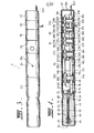
- Figure 3 is a side view of a detonator assembly;
- Figure 4 is a schematic sectional view through the detonator assembly of Figure 3;
- Figure 5 is a schematic view of lines in a communication bus;
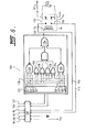
- Figure 6 shows the circuitry of one embodiment of a conditioning means according to the invention;
- Figure 7 shows the circuitry of another embodiment of a detonator unit;
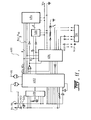
- Figure 8 is a schematic circuit diagram for an embodiment of a detonator actuator unit;
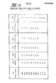
- Figure 9 is a connection table showing the connections of the components of Figure 8;
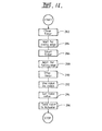
- Figure 10 is a flow diagram illustrating the operation of the detonator actuator unit of Figure 8;
- Figure 11 is a schematic circuit diagram for another embodiment of a detonator actuator unit;
- Figure 12 is a connection table showing the connections of the components of Figure 10;
- Figure 13 is a schematic circuit diagram for an embodiment of a transducer unit;
- Figure 14 is a flow diagram for the operation of a transducer programme;
- Figure 15 is a schematic circuit diagram of part of a detonator controller;
- Figure 16 is a connection table showing the connections of the components of Figure 15.
- Figure 17 is a flow diagram illustrating the operation of the controller;
- Figure 18 is a sectional view through an embodiment of a detonator assembly;
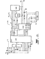
- Figure 19 is a schematic circuit diagram for an embodiment of a detonator actuator unit suitable with assemblies as shown in Figure 18;
- Figure 20 is a connection table showing the connections of the components of Figure 19;
- Figure 21 is a flow chart illustrating the operation of the circuit shown in Figure 19;
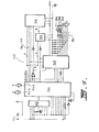
- Figure 22 is a schematic circuit diagram for an embodiment of a detonator actuator unit;
- Figure 23 is a connection table showing the connections of the components of Figure 22.
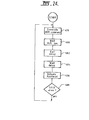
- Figure 24 is a flow diagram illustrating the operation of the detonator actuator circuit shown in Figure 22.
-
- Figure 1 shows a
quarry face 2 and a number ofcharge holes 4 drilled into the ground behind the face. Adetonator assembly 6 is located in eachhole 4 and the remainder of the hole is filled with abulk charge 8 such as ammonium nitrate fuel oil mixture which is supplied as a powder or slurry, in accordance with known practice. Thedetonator assemblies 6 are connected byconductors 10 to anantenna 11 for aradio transceiver 12 located in one or more of theassemblies 6. Thetransceiver 12 receives control signals from acontroller 14 via atransceiver 15 so that the detonator assemblies can be actuated by remote control. Asite safety unit 16 may also be provided to provide additional safety during laying of the charges. Theunit 16 is preferably located near theantenna 11 so as to be likely to pick up all signals received by theantenna 11. Thesafety unit 16 includes aloudspeaker 18 which is operated in emergency conditions and prior to a blast. Thedetonator assemblies 6 are arranged to be actuated at an accurately determined time after thecontroller 14 has transmitted signals for the blast to commence. Thedetonator assemblies 6 can be arranged to be activated in a precisely defined time sequence so that efficient use is made of the blasting materials. The number ofblast holes 4 can of course be very Iconsiderable. For instance, in some large scale mining and quarrying operations up to 2000 holes are sometimes required in a single blasting operation. - Figure 2 shows an arrangement which is similar to Figure 1 except that communication from the
controller 14 to thedetonator assemblies 6 is via awire 20 extending from thecontroller 14 to theconductors 10. In this case thesafety unit 16 is not required because of the hard wire connection between thecontroller 14 and thedetonator assemblies 6, but it could be coupled to thewires 20 so as to sound an alarm when signals are detected for causing actuation of the detonator assemblies. - Figure 3 shows the
detonator assembly 6 in more detail. As will be described hereinafter, it comprises a number of interconnected modules which can be varied in accordance with requirements. In the illustrated arrangement the modules comprise adetonator unit 22, anactuator unit 24, atransducer unit 26, abattery unit 38, anexpander unit 40 and aconnector unit 42. The units themselves can be made with various modifications as will be explained hereinafter. Generally speaking however adetonator assembly 6 in a useful configuration will include at least the following units: adetonator unit 22, anactuator unit 24, abattery unit 38 and aconnector unit 42. - Figure 4 shows a longitudinal cross section through the
detonator assembly 6 revealing in schematic form the physical layout of the components. - The
detor.ator unit 22 comprises atubular housing 44 which for instance might be formed from aluminium, or a resilient material which is a conductor such as ) carbonised rubber. Thehousing 44 is provided withtransverse partitions housing 44. Afirst chamber 50 is formed between thepartitions second chamber 52 is formed between thepartition 46 and theclosed end wall 54 of the housing. Extending into thesecond chamber 52 are twofusehead conductors block 60. Theconductors fusible element 62 located within a flashingmixture charge 64. The remainder of thesecond chamber 52 is filled or partly filled with abase charge 66 of explosive material. Theconductors portions opening 72 in thepartition 46 and into thefirst chamber 50. - Located within the
first chamber 50 is acircuit board 74 which mounts electronic and/or electric components. Theboard 74 is supported bytabs partitions partion 48 also supports a multiport connector 80 for abus 82. - The
bus 82 has multiple lines which enable electrical interconnection of the various modular units although not all of the lines are required for the functioning of particular units. Figure 5 shows schematically the various lines in thebus 82 for the illustrated arrangement. In this case there are 11lines board 74 of thedetonator unit 22. - Figure 6 illustrates diagrammatically a
circuit 106 which is mounted on theboard 74 of theunit 22. The 'circuit 106 includes aconnector 108 which allows connection to selected lines in thebus 82. In the illustrated arrangement, theline 84 is a voltage supply line and theline 86 is a ground line for the supply. Thelines element 62. Theline 104 carries clock pulses whereas theline 102 carries an ARM signal which places thedetonator unit 22 in a "armed" state so that it can be activated on receipt of appropriate driving currents on thelines lines actuator unit 24. Thepower supply lines battery unit 38. - The
circuit 106 includes arelay 110 having a drivingcoil 112, normally closedcontacts 114 and normallyopen contacts 116 which are connected toconductors lines connector 108. The normally closedcontacts 114 are connected by means ofconductors 117 to thealuminium housing 44 so that both sides of thefusible elements 62 are shorted directly to the housing. This is an important safety factor because thedetonator unit 22 cannot be activated unless therelay 110 is operated. This protects theunit 22 from unwanted operation caused by stray currents or radio frequency electromagnetic radiation. In the illustrated arrangement, therelay 110 is not operated until just before signals are delivered to thelines unit 22 is activated, thefuse head conductors element 62. - The operating
coil 112 of the relay is connected to alogic circuit 118 which receives input fromlines circuit 118 must receive an ARM signal comprising a two part four bit code on theline 102 in order to produce an output online 120 which activates the relay. - The
circuit 118 includes a 74164 eightbit shift register 122 having eight output lines Q0-Q7. The circuit further includes four exclusive ORgates shift register 122. The outputs of the exclusive OR gates are gated in a four input AND gate 132, the output of which is in turn connected to one input of a three input high current ANDgate 134. The circuit further includes a fourinput NAND gate 136 connected to the first four outputs of theregister 122 and asecond NAND gate 138 connected to the second four outputs of theregister 122. The outputs from theNAND gates gate 134. The configuration of the gates connected to the outputs Q0-Q7 of theregister 122 is such that only selected eight bit signals on theline 102 will cause a signal to appear on theoutput 120 for activating the relay. The signal must be such that the first four bits are exactly the complement of the second four bits and further the first four bits cannot be all I's or all 0's. The latter requirements are important in practice because it prevents erroneous operation of thecircuit 118 in the event that a circuit fault causing a high level or short circuit to be applied to theline 102. - The
circuit 106 illustrated above is given by way of example only and it would be apparent that many alternative circuits could be used. If at any time a signal is received online 102 which is not an ARM signal theoutput line 120 will go low and deactivate therelay 110. Thecontroller 14 may generate RESET signals for this purpose. In any event thelogic circuitry 118 will cause theoutput 120 to go low if any signal other than an ARM signal is received. The following are examples of valid ARM signalsFurther, the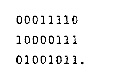
circuit 106 could be integrated if required, except for the relay. - Figure 7 illustrates an
alternative circuit 140 for thedetonator unit 22. The inputs from thebus 82 to theconnector 108 are the same as for thecircuit 106 and thelogic circuitry 118 is also the same as for thecircuit 106. An alternative arrangement is however employed to ensure that thelines fusible element 62 until just prior to actuation on receipt of a correctly coded signal to thelogic circuitry 118. In this arrangement, the circuit includes two solid state relays 142 and 144. The relays haveelectrodes electrodes conductors fusible element 62. The relays are such that theelectrodes electrodes conductors housing 44. The relays includeelectrodes lines conductors trigger electrodes electrodes electrodes conductors lines fusible element 62. Triggering of the relays depends upon theoutput line 120 from thelogic circuitry 118 as will hereinafter be explained. - The
output line 120 from thecircuitry 118 is connected to the input of anamplifier 162 which is connected to thejunction 164 of threefusible links resistance 172. The circuit includes an ANDgate 174 one input of which is connected to theoutput line 120 and the other input of which is connected to thejunction 164. Output from thegate 174 is connected to thetrigger terminals gate 174 are low so that the relays are not triggered. When however a correctly coded signal is present on theline 102, theoutput line 120 of thecircuitry 118 will go high to a sufficient extent whereby thefusible links junction 164 will be high and hence thegates 174 will go high and the relays will be triggered. This couples theconductors lines logic circuitry 118 detects a correctly coded signal, thefusible element 62 is protected by thefusible links conductors - The
detonator actuator 24 illustrated in Figures 3 and 4 includes atubular housing 176 preferably formed from aluminium. The unit includespartitions chamber 190 in which acircuit board 192 for electric and/or electronic components are mounted. Theboard 192 is supported bytabs bus 82 extends through thechamber 190 and is connected at either end toconnectors housing 176 is formed with a keyed reduceddiameter spigot portion 202 which in use is received in the free end of thehousing 44 of thedetonator unit 22. The arrangement is such that when thespigot portion 94 is interlocked with thehousing 44 theconnectors bus 82. Theactuator unit 24 may include anLED 204 which can be mounted so as to be visible when illuminated from the exterior of theactuator unit 24. - The
actuator unit 24 performs a variety of functions in thedetonator assembly 6. Generally speaking, it ensures that thedetonator unit 22 is actuated only in response to correctly received signals from thecontroller 14 and at an exactly defined instant of time. Other functions of theactuator unit 24 are to ensure correct operation of the other units in the assembly on interconnection of the various units and to control the operation of thetransducer unit 26. - Figure 8 shows in schematic form one arrangement for the
circuitry 206 mounted on theboard 192 in theactuator unit 24. Thecircuitry 206 generally speaking includes a microcomputer with memory to store programmes and data for correct operation of theunit 24 as well as the other units of the assembly. The data includes data relative to the precise delay required for actuation of thedetonator unit 22 following generation of a blast commence signal (or BOOM command) from thecontroller 14. Further, the stored programme provides for calibration of a crystal clock in thecircuitry 206 by thecontroller 14 just prior to operation. This ensures a high level of accuracy of all the time based functions of theassembly 6 which is therefore not dependent upon accurately selected components in thecircuit 206. Further the accuracy would not be influenced by temperatures and pressures in the blast holes 4 at a blasting site. - The
circuit 206 includes an 8085CPU 208, an 8155 input/output unit 210, a 2716EPROM 212, a 74123monostable retriggerable multivibrator 214 and a 74377 eightbit latch 216. The components are connected together as indicated in the connection table (Figure 9) so as to function as a microcomputer, as known in the art. - Figure 10 shows schematically a flow chart of some of the programme functions which are carried out by the
microcomputer 206. When power is supplied to the circuit by connection of thebattery unit 38 in the detonator assembly 6 a power supply voltage and ground are established on thelines multivibrator circuit 214 ensures that theCPU 208 is reset on power up. The first programming function performed by the microcomputer is to ensure that the detonator-units 22 are made safe. This is accomplished by sending eight consecutive zeros frompin 32 of the input/output device 210, thepin 32 being connected to theline 102. This ensures that theregister 122 in thedetonator 22 is initialised to zero and accordingly theunit 22 cannot be activated because of the arrangement of thelogic circuitry 118. This step is indicated by thefunctional block 218 in Figure 10. - After initialisation, the microcomputer waits for a command from the
controller 14 as indicated by programmingstep 220. Commands from thecontroller 14 are received by theconnector unit 42 and are then transmitted on theline 88 of thebus 82. The command signals online 88 preferably comprises eight bit codes in which different bit patterns represent different commands. Typical command signals would be for (a) a request for information from thetransducer unit 26, (b) a CALIBRATE command to commence calibration procedures, (c) a BLAST code for arming thedetonator units 22, (d) a BOOM command for exploding theunits 22, or a RESET command for resetting theunits 22. Accordingly, Figure 10 shows aquestion box 222 which determines whether the signal on theline 88 is a request for information from thetransducer unit 26. If the signal is the appropriate signal the programme will then enter a sub-routine indicated byprogramme step 224 to execute the transducer interrogation and transmission programme. A flow chart for this programme is shown in Figure 14. After execution of the transducer programme, the main programme returns to thequestion box 222. The signal on theline 88 will then no longer be a request for information from the transducer. The programme will then pass to thenext question box 226 which determines whether a signal is on theline 88 is a CALIBRATE command appropriate for commencement of calibration procedures. This is indicated in the flow chart byquestion box 226. If the signal is not a CALIBRATE command, the programme returns and waits for an appropriate command. Receipt of an incorrect command at any time returns the programme to the start. - When the
controller 14 transmits a CALIBRATE command, this will be recognized by the programme which then commences calibration of timing of pulses derived from thecrystal clock 228 connected topins CPU 208, as indicated bystep 230 in Figure 10. The programme then waits for a further signal online 88 to stop counting of the pulses and to record the number of pulses counted. This is indicated bystep 232 in Figure 10. These programming steps enable the clock rate of theCPU 208 to be accurately correlated to the signals generated by thecontroller 14 and transmitted on theline 88 so that theactuator unit 24 can be very accurately calibrated relative to thecontroller 14. ' Thecontroller 14 can be arranged to have a precisely defined time base so that it therefore is able to accurately calibrate a multiplicity ofactuators 24 which do not have accurately selected components and would therefore not necessarily have a very accurately ' known time base. - Moreover, the calibration procedures can be carried out just prior to despatch of signals to activate the detonator units so as to minimize the possibility of errors owing to changing conditions of temperature and pressure or the like.
- In the preferred arrangement, the signal on the
line 88 to stop the timer is in fact another BLAST code generated by thecontroller 14, the BLAST code being selected so as to be identifiable with the particular blast e.g. user identity, date, sequential blast number, etc. Thequestion box 234 in Figure 10 indicates the required programming step. If the next signal received on theline 88 is not a correct BLAST code, the programme returns to the start so that recalibration will be required before thedetonator unit 22 can be armed. - If on the other hand the BLAST code is correct the programme then calculates the exact delay required by the
actuator 24 prior to generating signals for explosively activating thedetonator unit 22. This is indicated by theprogramming step 236 in Figure 10. For instance, theactuator unit 24 may be required to actuate thedetonator unit 22 precisely 10 ms after a precise predetermined delay from commencement of the blasting sequence which is initiated by generation of a BOOM command by thecontroller 14. The information regarding the particular delay is stored in theEPROM 212 and the programme is then able to calculate the exact number of clock cycles for themicrocomputer 206 required to give the precise delay. The calibration information has in the meantime been stored in RAM within the input/output device 210. - Following this step, the
actuator unit 24 may signal to thecontroller 14 that it is functioning correctly and that appropriate signals have been received. Signals for"transmission back to thecontroller 14 are carried byline 90 which is coupled to pin 4 of theCPU 208. This is indicated bystep 238 in Figure 10. The arming of thedetonator unit 22 is indicated bystep 240 in which an ARM signal is generated onpins 31 and 32 of input/output unit 210. The programme then is arranged to set a predetermined period say 5 seconds in which it must receive a BOOM command signal on theline 88 from thecontroller 14 for activation of thedetonator unit 22. If the BOOM command signal is not received within the 5 second period, the programme returns to the start so that recalibration procedures etc. will be required in order to again be in readiness for actuation of thedetonator unit 22. These programming steps are denoted 242, 244 and 246 in Figure10. The BOOM command signal online 88 must be a correct eight bit pattern of signals otherwise the programme will again return to the start, as indicated by thequestion box 248. If the BOOM command is correct, the required delay is retrieved from the RAM in the input/output unit 210 and the delay is waited, as indicated by programmingsteps output unit 210 the output pins 29 and 30 of which go high. These output pins are connected bycurrent drivers lines element 62 and ignite theflashing charge 64 and thus actuate thedetonator unit 22. This is indicated by theprogramming step 258. Actuation of thedetonator unit 22 of course destroys thedetonator assembly 6 so that thecontroller 14 will be aware of successful operation of the detonator assembly by its silence. If however there has been a malfunction, the programme includes a question box 26C which determines whether the CPU is still functioning and if so this information is communicated toline 90 for transmission to thecontroller 14. The programme then returns to the start whereupon the detonator unit is again made safe, this being indicated by programmingsteps - Figure 11 illustrates alternative circuitry for the
actuator unit 24. In this arrangement, thepower supply lines controller 14 to theactuator assembly 6. The same lines may be utilised for communications in the reverse direction if atransducer unit 26 is utilised. Alternatively theline 90 may be used for that purpose if required as shown in Figure 11. The circuit of Figure 11 essentially comprises amicrocomputer 490 comprising and 8085CPU 492, a 2716EPROM 494, an 8155 input/output unit 496, a 74123 triggerablemonostable multivibrator 498 and a 74377 eightbit latch 500. These components are connected together as indicated in the connection table (Figure 12) so as to function as a microcomputer as is known in the art. The principle function of themicrocomputer 490 is to carry out the programming steps indicated ciagramatically in Figure 10 as well as Figure 14 where atransducer unit 26 is employed. - Power supply for the
detonator assembly 6 is derived from the voltage applied to theline 84 by thecontroller 14 via theconductors 10 andwires 20 of Figure 2. The voltage is stored in a storage capacitor 504. Thediode 502 ensures the capacitor 504 cannot discharge itself back along the path to pin 5 of theCPU 492, or to thecontroller 14 alongconductors line 84 is selected to be 2.4 volts which is sufficient to charge the capacitor 504 and maintain theCPU 492 but insufficient to generate a response on theinput pin 5 of theCPU 492 which is connected to theline 84. When signals are required to be transmitted to theassembly 6 from the controller, the controller is arranged to send a pulsed waveform the peak voltages of which are say 5 volts which is above the threshold level for a positive input to thepin 5 of theCPU 492. By this means, various coded signals can be sent from thecontroller 14 to the assemblies. Theoutput pin 4 could be used to apply voltages to theline 84 for communication from theassembly 6 to the controller, provided the time sequencing were correctly arrang-d. Alternately, theoutput pin 4 could be connected to thereturn communication line 90 of the bus. - Returning now to Figures 3 and 4, the
transducer unit 26 comprises atubular housing 264 preferably of aluminium and formed with aspigot portion 266 which interlocks with the open end of thehousing 176 of theactuator unit 24. The shape is such that it cannot mate with theunit 22. The housing has partitions 268 and 270 which define a chamber in which acircuit board 272 for electronic and/or electrical components is located. The partitions 26E and 270 can be used to support theboard 272 as well as supportingelectrical connectors 272 and 274 for thebus 82. Thehousing 264 has an opening to permit access to atransducer element 276 which is sensitive to surrounding temperature, pressure, humidity or other parameters as required. For temperature sensing theelement 276 could be bonded to the inner surface of thehousing 264. Thetransducer unit 26 may have several transducer elements and so be responsive to a number of different parameters. When thespigot portion 266 is interlocked with the end of theactuator unit 24, theconnector 272 mates with theconnector 200 so that thebus 82 extends through the respective units. In its simplest configuration, theboard 272 would simply carry any circuitry which might be necessary for correct operation of thetransducer element 276 and for coding of its output for application tolines bus 82. - Figure 13 shows an example of one such circuit. In this arrangement the output 278 of the
transducer element 276 is connected to the input of a voltage tofrequency converter 280 which may comprise an LM 331 circuit. The resistors and capacitors connected to theconverter 280 are well known and need not be described in detail. Output frompin 3 of theconverter 280 is connected to theline 98 of the bus, theline 100 being ground. The frequency of the signal on theline 98 will be proportional to the output of thetransducer element 276 and thus be proportional to the temperature pressure humidity etc. to which theelement 276 is exposed. The signal on theline 98 is applied to theCPU 208 for conversion to digital form and outputted onpin 4 which is coupled toline 90 of the bus for transmission to thecontroller 14. - Figure 14 shows schematically a flow chart for processing by the
microcomputer 206 of the variable frequency output signals of thetransducer unit 26. The flow chart of Figure 14 is an example of the programme denoted by 224 in Figure 10. The first step in the programme is to clear a timer, as indicated byprogramme step 282. The timer may be located in the input/output unit 210. The programme then waits for the rising edge of the first received pulse on theline 98, as indicated bystep 284. The programme then starts the timer and waits for a falling edge of the same pulse, as indicated bysteps EPROM 212, as indicated bysteps controller 14 vialine 90, as indicated bysteps actuator unit 24, as indicated in Figure 10. - In circumstances where communication from the
detonator assemblies 6 to thecontroller 14 is not required, theconnector unit 42 need only be capable of receiving signals from thecontroller 14 and does not need to transmit signals thereto. Thus, theunit 42 need only include a radio receiver for use with radio controlled arrangements as in Figure 1, or line connectors for use in wire systems as shown in Figure 2. - Returning once again to Figures 3 and 4, the
battery unit 38 comprises atubular housing 298 with a spigot portion 300 which is interlockable with the open end of thehousing 264 of thetransducer unit 26. The spigot 300 is also shaped so that it can be plugged directly into thehousing 176 of theactuator unit 24 in instances where thetransducer 26 is not required. The shape of the spigot 300 is such that it cannot be inserted into the open end of thehousing 44 of thedetonator unit 22. Theunit 38 includespartitions battery 306 is mounted. The battery provides the power supply onlines battery unit 38 may be omitted by arranging for one or more of the other units such as theactuator 24 to have an inbuilt battery or to be provided with energy storage means such as a capacitor for powering the units or to have power supplied by thecontroller 14 itself, as onlines lines 20. Thebattery unit 38 has connectors 30E and 310 to provide interconnections of thebus 82 through the unit. - Figures 3 and 4 also show the
expander unit 40 in more detail. The expander unit comprises atubular housing 312 formed with aspigot 314 which can be inserted into the housings of theunits partitions terminal block 320 is mounted. The partitions also supportconnectors 322 and 324 for thebus 82. Extending from theterminal block 320 through an opening in thehousing 312 arelines 326 which can be used to connect a number of detonator assemblies in parallel, as shown in Figures 13 and 14. Figures 3 and 4 also illustrate theconnector unit 42. Theunit 42 comprises a tubular housing 328 with aclosed end wall 330. The housing has a partition 322 which defines a chamber within which acircuit board 334 is mounted. The partition 332 also supports aconnector 336. The housing 328 is formed with a spigot portion 338 which is insertable in any one of theunits connector 336 mates with the complementary connector of the unit to which it is connected. Theunit 42 is not however directly insertable in thedetonator unit 22. - The
circuit board 334 in theunit 42 may comprise a connection block which connects thewires 20 from thecontroller 14 to theassemblies 6, as in the arrangement shown in Figure 2. This is the simplest arrangement for theunit 42. - In another alternative arrangement for the
unit 42, theboard 334 may include an electronic clock and signal generator to enable activation of theactuator unit 24 independently of thecontroller 14. In this arrangement (not shown) the clock would control a signal generator which would generate signals foractuator unit 24 via theline 88 which signals would normally be generated by thecontroller 14. - In a further alternative arrangement, the
unit 42 may include theradio transceiver 12 which receives signals radiated by thetransmitter 15 or thesafety unit 16, as in the arrangement of Figure 1. In this instance, thelines 340 which comprise the input to the circuitry on theboard 334 would comprise or be connected to an antenna for receipt of radio signals. - Figure 15 illustrates in more detail part of the circuitry for the
controller 14. The circuitry essentially comprises amicrocomputer 342 comprising an 8055CPU 344, a 2716EPROM 346, an 8155 input/output device 348, a 74123 monostabletriggerable multivibrator 352 and a 74377eightbit latch 350. These components are connected together as indicated by the connection table (Figure 16) and so that they function as a microcomputer as is known in the art. The principal function of themicrocomputer 342 is to generate control signals which are used to control thedetonator assemblies 6. The microcomputer also interprets information sent to thecontroller 14 by thevarious detonator assemblies 6, input and output to theCPU 344 is viapins keyboard unit 354, the keyboard having control switches Sl, S2, S3 and S4 which are operated in order to perform various steps required for activation of thedetonator assemblies 6. The microcomputer includes threeLED devices computer 342 to thedetonator assemblies 6. The programmes for themicrocomputer 342 are stored in theEPROM 346. - Figure 17 is a flowchart illustrating the important programming steps which are carried out by the
computer 342. On power up, themultivibrator 352 ensures that theCPU 344 is correctly initialised and the programme waits for one of the control keys Sl to S4 to be actuated, as indicated bystep 362. The programme then has fourquestion boxes assemblies 6. For instance, the switch Sl can be made to represent selection of a first BLAST code in which case theCPU 344 generates the appropriate BLAST code. The programme then arranges for the BLAST code to be sent to thedetonator assemblies 6, as indicated byprogramme step 372. It follows that those detonators which have the first BLAST code will be armed in readiness for operation. After that signal is sent, the programme returns to the start. The switch S2 may represent a second BLAST code which will cause a different BLAST code to be generated by theCPU 444 and sent to thedetonator assemblies 6, as indicated bystep 374. Those assemblies which have actuatorunits 24 programmed to respond to the second BLAST code will thereby be armed. - The switch S3 if pressed causes the
CPU 334 to generate a signal causing thearmed actuator units 24 to actuate thedetonator units 22 connected thereto. These signals comprise the BOOM command and are distinguished by thequestion box 248 in Figure 9. The despatch of a BOOM command is indicated byprogramme step 376 in Figure 13. - The switch S4 represents a reset switch which can be activated by an operator at any stage during the programme and if pressed a RESET command will be generated by the
CPU 344, as indicated bystep 378. Receipt of a RESET command by theactuator units 24 causes them to return to the start of their operating programme, as indicated in Figure 10. The reset signal need not be a specially encoded signal, theactuator units 24 being programmed to automatically reset if any signals other than known sequence of predetermined commands are received. Resetting theactuators 24 will consequently make thedetonator units 22 safe so that they cannot be inadvertently exploded. Of course, adetonator unit 22 with fusible links as shown in Figure 7 cannot reconnect thefusehead conductors - The controller programme has a
question box 380 which is responsive to a manual or programme generated input to commence calibration procedures. The arrangement shown in Figure 16 shows astep 382 for generation and transmission of a CALIBRATE command to start calibration. This command is the input-tobox 226 in Figure 10.The programme then waits for a predetermined period say one second which is accurately known because care is taken to ensure that the crystal oscillator 386 and associated components connected topins CPU 344 are accurately selected whereby the timing of theCPU 344 is accurately known. At the end of the predetermined period, an END calibrate command is generated as indicated by thestep 388. This may be effected by generation of a valid BLAST code. Many variations and enhancements would of course be available in the software for themicrocomputer 342. - Figure 18 shows a
detonator assembly 434 comprising adetonator unit 22,actuator unit 24 andconnector unit 42. In this arrangement theconnector unit 42 is arranged for connection to thecontroller 14 by theconductors 10 andwires 20, as in Figure 2. Th;detonator assembly 434 receives power directly from thecontroller 14 and to be actuated at a predetermined interval after voltage has been disconnected from thewires 20. In a blast using these assemblies, it would not matter if thewire 20 orconductors 10 were broken by actuation of assemblies which have been actuated earlier since the assemblies have their own power supplies and will be actuated at a predetermined period after the voltage has been disconnected regardless of whether theconductors 10 orwires 20 remain intact. - Figure 19 illustrates in more detail the circuitry for the
actuator unit 24 ofassembly 434. The circuitry essentially comprises amicrocomputer 436 comprising an 8055CPU 438, a 2176EPROM 440, an 8155 input/output device 442, a 74123triggerable multivibrator 444, and a 74377 eightbit latch 446. These components are connected together as indicated by the connection table (Figure 20) so that they function as a microcomputer as is known in the art. The principle function of themicrocomputer 436 is to generate control signals which are used to control thedetonator assembly 436. In this arrangement, thepower supply line 84 andground line 86 are connected to theconductors 10 so as to establish direct connection to thecontroller 14. The voltage on thepower supply line 84 charges astorage capacitor 450. Thediode 448 ensures that the "power sense"line 5 can detect the discontinuation of power from thecontroller 14 online 84 even while thecapacitor 450 maintains theactuator 436 on. Thecapacitor 450 is chosen so that it will have sufficient charge to power the circuitry for themicrocomputer 436 after the voltage supply level has been removed fromsupply line 84. As soon as themultivibrator 444 operates aft2r power on, it will properly initialise theCPU 438. Theinput pin 5 of the CPU is connected to theline 84 so as to indicate a "power up". After power up, themicroprocessor 436 will operate to generate an ARM command which is communicated viapins 31 and 32 of theunit 472 to thedetonator unit 22. TheCPU 438 will then wait until the voltage falls to zero or below a predetermined level online 84, and, after a predetermined period, the fusehead actuating current will be generated to initiate the flashingcharge 64 viapins - Figure 21 is a flowchart illustrating the important programming steps which are carried out by the
microcomputer 436. The programme starts on power up and then immediately generates an ARM command, as indicated bystep 452, for thedetonator unit 22. The ARM command will then wait for a predetermined period say 0.25 seconds before taking any other action. This prevents premature operation of the system as the result of transients or the like which might occur shortly after power up, and allows time for mechanical relays in thedetonator unit 22 to switch. This step is indicated by programmingstep 454. The programme then waits for the voltage to fall online 84, as indicated bystep 456. When the voltage online 84 falls to zero or below a pre-determined level the CPU will then wait a pre-determined delay so that thedetonator assembly 434 will be actuated in the correct sequence relative to other assemblies. This is indicated by programmingsteps 458 and 460 representing retrieval of the delay period from theEPROM 440 and thereafter waiting the delay period. At the end of the delay period, the programme then causes generation of the fusehead actuating current for actuation of thedetonator unit 22, as indicated bystep 462. The programme then passes to aquestion box 464 which ascertains whether the programme is still operating indicating whether thedetonator unit 22 has been successfully actuated or not. If it has not, it will return to thestep 452. - Figure 22 shows an alternative circuit for use in the
actuator unit 24 of theassembly 436, shown in Figure 19. In this arrangement thedetonator assembly 434 is arranged to be actuated a predetermined period after power has been applied thereto via theconductors 10 andwires 20 of the arrangement shown in Figure 2. The circuit of Figure 22 essentially comprises amicrocomputer 466 comprising an 8085CPU 468, a 2176EPROM output unit 472, a 74123 monostabletriggerable multivibrator 474, and a 74377 eightbit latch 474. These components are connected together as indicated by the connection table (Figure 23) so that they function as a microprocessor as is known in the art. The microcomputer has programmes stored in itsEPROM 470 for carrying out primarily the programme shown diagramatically in the flowchart of Figure 24. - On the application of a voltage above a predetermined level, e.g. 2.4 volts, on the
supply line 84, themultivibrator 474 will reset theCPU 468 and various circuit and programming functions are properly initialised. TheCPU 468 will then start running and its first function will be to generate an ARM command onpins 31 and 32 of theunit 472 for thedetonator unit 22. This is indicated by theprogramming step 478 of Figure 24. The programme then waits a fixed delay period as indicated bystep 480. The fixed delay period say 0.25 seconds, is provided to as to prevent inadvertent operation caused by transients or the like which might occur shortly after power up, and allow time for relays to switch. All of the detonator assemblies for a particular blast would have the same fixed delay period. The programme then reads a pre-selected delay from theEPROM 470, as indicated byprogramme step 482. The pre-selected delay can be different forparticular actuator units 24 so that a predetermined blast sequence can be established. The programme then waits for the preselected delay period, as indicated byprogramme step 482 then causes generation of the fusehead actuating current viapins 29 and 39 of theunit 472 as indicated bystep 486. The BOOM command appears onpins unit 472. The BOOM command causes thedetonator unit 22 to explode. - If the
unit 22 fails to explode, the programme will pass toquestion box 488 which will return the programme to the start if themicrocomputer 466 has remained in tact. - Many modifications will be apparent to those skilled in the art. For instance, integration techniques could be used to integrate circuits which are shown in non-integrated form.
- The blasting system according to my invention is useful in commercial blasting. The system offers higher degrees of versatility, safety and security than are attainable by systems currently known to and used by the art. The components of the blasting system can be easily manufactured using equipment and techniques known to the explosives and electronics industries, and their use in the field is straightforward.
Claims (10)
Priority Applications (1)
| Application Number | Priority Date | Filing Date | Title |
|---|---|---|---|
| AT86304991T ATE73539T1 (en) | 1985-06-28 | 1986-06-26 | IGNITION SYSTEM. |
Applications Claiming Priority (6)
| Application Number | Priority Date | Filing Date | Title |
|---|---|---|---|
| AU1256/85 | 1985-06-28 | ||
| AUPH125985 | 1985-06-28 | ||
| AUPH125685 | 1985-06-28 | ||
| AU1259/85 | 1985-06-28 | ||
| AU1257/85 | 1985-06-28 | ||
| AUPH125785 | 1985-06-28 |
Publications (3)
| Publication Number | Publication Date |
|---|---|
| EP0208480A2 true EP0208480A2 (en) | 1987-01-14 |
| EP0208480A3 EP0208480A3 (en) | 1988-01-27 |
| EP0208480B1 EP0208480B1 (en) | 1992-03-11 |
Family
ID=27157258
Family Applications (1)
| Application Number | Title | Priority Date | Filing Date |
|---|---|---|---|
| EP86304991A Expired EP0208480B1 (en) | 1985-06-28 | 1986-06-26 | Detonator actuator |
Country Status (9)
| Country | Link |
|---|---|
| US (2) | US4860653A (en) |
| EP (1) | EP0208480B1 (en) |
| AT (1) | ATE73539T1 (en) |
| DE (1) | DE3684187D1 (en) |
| ES (1) | ES2000184A6 (en) |
| GB (1) | GB2179123B (en) |
| NO (1) | NO870832L (en) |
| PH (1) | PH26351A (en) |
| WO (1) | WO1987000265A1 (en) |
Cited By (11)
| Publication number | Priority date | Publication date | Assignee | Title |
|---|---|---|---|---|
| EP0279796A1 (en) * | 1987-02-16 | 1988-08-24 | Nitro Nobel Ab | Detonator |
| EP0356908A3 (en) * | 1988-08-27 | 1990-06-13 | Honeywell Regelsysteme Gmbh | Method and device for functional control of a weapon system |
| US4986183A (en) * | 1989-10-24 | 1991-01-22 | Atlas Powder Company | Method and apparatus for calibration of electronic delay detonation circuits |
| WO1991007637A1 (en) * | 1986-11-06 | 1991-05-30 | Electronic Warfare Associates, Inc. | Remote detonation of explosive charges |
| EP0434883A1 (en) * | 1989-12-29 | 1991-07-03 | Union Espanola De Explosivos S.A. | Electronic detonators-exploder system for high-reliable stepped detonation |
| WO1996023195A1 (en) * | 1995-01-24 | 1996-08-01 | Explosive Developments Limited | Explosive firing circuit |
| FR2742859A1 (en) * | 1995-12-21 | 1997-06-27 | France Etat | PROGRAMMABLE TIME PRIMING DEVICE |
| DE19721839A1 (en) * | 1997-04-15 | 1998-10-22 | Dynamit Nobel Ag | Electronic detonator |
| WO2000040920A1 (en) * | 1999-01-08 | 2000-07-13 | Dynamit Nobel Gmbh Explosivstoff- Und Systemtechnik | Two-piece capsule trigger unit for initiating pyrotechnic elements |
| US8069789B2 (en) | 2004-03-18 | 2011-12-06 | Orica Explosives Technology Pty Ltd | Connector for electronic detonators |
| AU2022100135B4 (en) * | 2015-09-16 | 2022-12-01 | Orica International Pte Ltd | A wireless initiation device |
Families Citing this family (100)
| Publication number | Priority date | Publication date | Assignee | Title |
|---|---|---|---|---|
| DE3515703C1 (en) * | 1985-05-02 | 1996-05-09 | Dynamit Nobel Ag | Mine arming system with mine disabling facility |
| WO1987000265A1 (en) * | 1985-06-28 | 1987-01-15 | Moorhouse, D., J. | Detonator actuator |
| US5117756A (en) * | 1989-02-03 | 1992-06-02 | Atlas Powder Company | Method and apparatus for a calibrated electronic timing circuit |
| US4977598A (en) * | 1989-04-13 | 1990-12-11 | Texas Instruments Incorporated | Efficient pruning algorithm for hidden markov model speech recognition |
| US5157222A (en) * | 1989-10-10 | 1992-10-20 | Joanell Laboratories, Inc. | Pyrotechnic ignition apparatus and method |
| US5488908A (en) * | 1994-04-22 | 1996-02-06 | Paul C. Gilpin | Environmetally insensitive electric detonator system and method for demolition and blasting |
| JP2000501496A (en) * | 1995-12-06 | 2000-02-08 | オリカ トレーディング プロプライアタリー リミティド | Electronic detonator |
| US5877696A (en) * | 1996-04-09 | 1999-03-02 | Powell; Roger A. | Security system for warheads |
| FR2749073B1 (en) | 1996-05-24 | 1998-08-14 | Davey Bickford | PROCEDURE FOR ORDERING DETONATORS OF THE TYPE WITH ELECTRONIC IGNITION MODULE, FIRE CONTROL CODE ASSEMBLY AND IGNITION MODULE FOR ITS IMPLEMENTATION |
| US5767437A (en) * | 1997-03-20 | 1998-06-16 | Rogers; Donald L. | Digital remote pyrotactic firing mechanism |
| EP0975932A1 (en) * | 1997-04-15 | 2000-02-02 | Dynamit Nobel GmbH Explosivstoff- und Systemtechnik | Electronic igniter |
| AUPP021697A0 (en) | 1997-11-06 | 1997-11-27 | Rocktek Limited | Radio detonation system |
| US6014932A (en) * | 1997-11-18 | 2000-01-18 | Technology Patents, Llc | Land mine arming/disarming system |
| US6112668A (en) * | 1998-02-17 | 2000-09-05 | The United States Of America As Represented By The Secretary Of The Navy | Magneto-inductively controlled limpet |
| US6263989B1 (en) * | 1998-03-27 | 2001-07-24 | Irobot Corporation | Robotic platform |
| US6260483B1 (en) * | 1998-04-24 | 2001-07-17 | Richard N. Snyder | Remote radio controlled plasma firing system |
| EP1105693B1 (en) * | 1998-08-13 | 2007-07-11 | Orica Explosives Technology Pty Ltd | Blasting arrangement |
| DE19849079A1 (en) * | 1998-10-24 | 2000-04-27 | Bayerische Motoren Werke Ag | Process for disarming pyrotechnic actuators in a vehicle |
| FR2787568B1 (en) * | 1998-12-16 | 2001-02-02 | France Etat | DEVICE FOR FIREING A PRIMER |
| DE19945303B4 (en) * | 1999-01-08 | 2011-09-15 | Orica Explosives Technology Pty. Ltd. | Tripping unit for initiating pyrotechnic elements with two-part capsule |
| DE19912688B4 (en) * | 1999-03-20 | 2010-04-08 | Orica Explosives Technology Pty. Ltd., Melbourne | Method for exchanging data between a device for programming and triggering electronic detonators and the detonators |
| WO2000063636A1 (en) * | 1999-04-20 | 2000-10-26 | Expert Explosives (Proprietary) Limited | Method of and system for controlling a blasting network |
| US8412377B2 (en) | 2000-01-24 | 2013-04-02 | Irobot Corporation | Obstacle following sensor scheme for a mobile robot |
| US8788092B2 (en) | 2000-01-24 | 2014-07-22 | Irobot Corporation | Obstacle following sensor scheme for a mobile robot |
| AU2001216836A1 (en) * | 2000-02-11 | 2001-08-20 | Inco Limited | Remote wireless detonator system |
| AUPQ591000A0 (en) | 2000-02-29 | 2000-03-23 | Rockmin Pty Ltd | Cartridge shell and cartridge for blast holes and method of use |
| US6956348B2 (en) | 2004-01-28 | 2005-10-18 | Irobot Corporation | Debris sensor for cleaning apparatus |
| US7644661B1 (en) * | 2000-09-06 | 2010-01-12 | Ps/Emc West, Llc | Networked electronic ordnance system |
| US7752970B2 (en) | 2000-09-06 | 2010-07-13 | Ps/Emc West, Llc | Networked electronic ordnance system |
| US6690134B1 (en) | 2001-01-24 | 2004-02-10 | Irobot Corporation | Method and system for robot localization and confinement |
| US7571511B2 (en) * | 2002-01-03 | 2009-08-11 | Irobot Corporation | Autonomous floor-cleaning robot |
| CA2441471C (en) | 2001-06-06 | 2006-08-08 | Senex Explosives, Inc. | System for the initiation of rounds of individually delayed detonators |
| US8396592B2 (en) * | 2001-06-12 | 2013-03-12 | Irobot Corporation | Method and system for multi-mode coverage for an autonomous robot |
| US7429843B2 (en) * | 2001-06-12 | 2008-09-30 | Irobot Corporation | Method and system for multi-mode coverage for an autonomous robot |
| US6915744B2 (en) * | 2001-07-05 | 2005-07-12 | Special Devices, Inc. | Pyrotechnic initiator with on-board control circuitry |
| US6679175B2 (en) | 2001-07-19 | 2004-01-20 | Rocktek Limited | Cartridge and method for small charge breaking |
| US7559269B2 (en) | 2001-12-14 | 2009-07-14 | Irobot Corporation | Remote digital firing system |
| US8375838B2 (en) * | 2001-12-14 | 2013-02-19 | Irobot Corporation | Remote digital firing system |
| US6860206B1 (en) | 2001-12-14 | 2005-03-01 | Irobot Corporation | Remote digital firing system |
| US9128486B2 (en) | 2002-01-24 | 2015-09-08 | Irobot Corporation | Navigational control system for a robotic device |
| AU2003200490B2 (en) * | 2002-02-20 | 2008-05-08 | Rocktek Ltd. | Apparatus and method for fracturing a hard material |
| AU2003223795B2 (en) * | 2002-03-28 | 2009-05-07 | Orica Explosives Technology Pty Ltd | System and method for monitoring features of a blast |
| US20030221576A1 (en) * | 2002-05-29 | 2003-12-04 | Forman David M. | Detonator with an ignition element having a transistor-type sealed feedthrough |
| AU2003254393B2 (en) * | 2002-08-30 | 2008-06-26 | Orica Explosives Technology Pty Ltd. | Access control for electronic blasting machines |
| US8386081B2 (en) | 2002-09-13 | 2013-02-26 | Irobot Corporation | Navigational control system for a robotic device |
| US8428778B2 (en) | 2002-09-13 | 2013-04-23 | Irobot Corporation | Navigational control system for a robotic device |
| US6962202B2 (en) * | 2003-01-09 | 2005-11-08 | Shell Oil Company | Casing conveyed well perforating apparatus and method |
| US7337723B2 (en) * | 2003-07-15 | 2008-03-04 | Detnet South Africa (Pty) Ltd. | Detonator arming |
| US7107908B2 (en) * | 2003-07-15 | 2006-09-19 | Special Devices, Inc. | Firing-readiness diagnostic of a pyrotechnic device such as an electronic detonator |
| US6941870B2 (en) * | 2003-11-04 | 2005-09-13 | Advanced Initiation Systems, Inc. | Positional blasting system |
| US8474379B2 (en) * | 2004-01-16 | 2013-07-02 | Rothenbuhler Engineering Co. | Remote firing device with diverse initiators |
| US7332890B2 (en) | 2004-01-21 | 2008-02-19 | Irobot Corporation | Autonomous robot auto-docking and energy management systems and methods |
| KR101214723B1 (en) | 2004-06-24 | 2012-12-24 | 아이로보트 코퍼레이션 | Remote control scheduler and method for autonomous robotic device |
| US8972052B2 (en) | 2004-07-07 | 2015-03-03 | Irobot Corporation | Celestial navigation system for an autonomous vehicle |
| US7706917B1 (en) | 2004-07-07 | 2010-04-27 | Irobot Corporation | Celestial navigation system for an autonomous robot |
| US7594471B2 (en) * | 2004-07-21 | 2009-09-29 | Detnet South Africa (Pty) Ltd. | Blasting system and method of controlling a blasting operation |
| PE20060926A1 (en) | 2004-11-02 | 2006-09-04 | Orica Explosives Tech Pty Ltd | ASSEMBLIES OF WIRELESS DETONATORS, CORRESPONDING BLASTING APPLIANCES AND BLASTING METHODS |
| WO2006076777A1 (en) * | 2005-01-24 | 2006-07-27 | Orica Explosives Technology Pty Ltd | Wireless detonator assemblies, and corresponding networks |
| ES2346343T3 (en) | 2005-02-18 | 2010-10-14 | Irobot Corporation | AUTONOMOUS SURFACE CLEANING ROBOT FOR DRY AND WET CLEANING. |
| US7620476B2 (en) | 2005-02-18 | 2009-11-17 | Irobot Corporation | Autonomous surface cleaning robot for dry cleaning |
| US8392021B2 (en) | 2005-02-18 | 2013-03-05 | Irobot Corporation | Autonomous surface cleaning robot for wet cleaning |
| FR2882816A1 (en) * | 2005-03-04 | 2006-09-08 | Delta Caps Initiators Soc Par | INTERFACE DEVICE FOR DETONATORS |
| US8930023B2 (en) * | 2009-11-06 | 2015-01-06 | Irobot Corporation | Localization by learning of wave-signal distributions |
| EP2816434A3 (en) | 2005-12-02 | 2015-01-28 | iRobot Corporation | Autonomous coverage robot |
| EP2533120B1 (en) | 2005-12-02 | 2019-01-16 | iRobot Corporation | Robot system |
| US8584305B2 (en) | 2005-12-02 | 2013-11-19 | Irobot Corporation | Modular robot |
| EP2829939B1 (en) | 2005-12-02 | 2019-11-13 | iRobot Corporation | Autonomous coverage robot navigation system |
| KR101300492B1 (en) | 2005-12-02 | 2013-09-02 | 아이로보트 코퍼레이션 | Coverage robot mobility |
| WO2007124539A1 (en) * | 2006-04-28 | 2007-11-08 | Orica Explosives Technology Pty Ltd | Wireless electronic booster, and methods of blasting |
| US8528157B2 (en) | 2006-05-19 | 2013-09-10 | Irobot Corporation | Coverage robots and associated cleaning bins |
| US8417383B2 (en) | 2006-05-31 | 2013-04-09 | Irobot Corporation | Detecting robot stasis |
| US20080098921A1 (en) * | 2006-10-26 | 2008-05-01 | Albertus Abraham Labuschagne | Blasting system and method |
| US20080174448A1 (en) * | 2006-10-31 | 2008-07-24 | Edison Hudson | Modular Controller |
| RS49942B (en) * | 2007-01-30 | 2008-09-29 | Lazar Kričak | SYSTEM FOR PROGRAMMED INITIATION OF ELECTRICAL AND NON-ELECTRICAL DETONATOR NETWORKS USING RF TRANSMISSION SYSTEM |
| ES2559128T3 (en) * | 2007-05-09 | 2016-02-10 | Irobot Corporation | Autonomous compact covering robot |
| US20110226148A1 (en) * | 2008-05-16 | 2011-09-22 | Sawka Wayne N | Physical destruction of electrical device and methods for triggering same |
| NZ592333A (en) * | 2008-10-24 | 2014-10-31 | Battelle Memorial Institute | Electronic detonator system |
| WO2010051776A1 (en) * | 2008-11-10 | 2010-05-14 | 北京铱钵隆芯科技有限责任公司 | Setting flow for delay time of a blasting device and controlling flow for an electronic detonator in an electronic detonator blasting system |
| KR101497197B1 (en) | 2010-02-16 | 2015-02-27 | 아이로보트 코퍼레이션 | Vacuum brush |
| CN103339465A (en) * | 2010-11-03 | 2013-10-02 | 欧米亚集团(私有)有限公司 | Connector |
| US8408908B1 (en) * | 2010-11-18 | 2013-04-02 | Lockheed Martin Corporation | Non-pyrotechnic detonation simulator |
| US20120250208A1 (en) * | 2011-03-28 | 2012-10-04 | Casedhole Solutions, Inc. | Electronic Switch and Circuit for Select-Fire Perforating Guns |
| US10267611B2 (en) | 2011-04-28 | 2019-04-23 | Orica International Pte Ltd. | Wireless detonators with state sensing, and their use |
| JP5849972B2 (en) * | 2013-01-08 | 2016-02-03 | 日油株式会社 | Radio detonator, parent die, radio detonation system, and radio detonation method |
| CN109372475B (en) | 2013-08-26 | 2021-05-18 | 德国德力能有限公司 | Perforating gun and detonator assembly |
| EP3123103B1 (en) * | 2014-03-27 | 2019-05-01 | Orica International Pte Ltd | Apparatus, system and method for blasting using magnetic communication signal |
| DE102014209204B3 (en) * | 2014-05-15 | 2015-04-09 | Ifm Electronic Gmbh | Electronic circuit for controlling an actuator |
| AU2015353394B2 (en) * | 2014-11-28 | 2020-04-02 | Detnet South Africa (Pty) Ltd | Electronic detonator initiation |
| WO2017083885A1 (en) * | 2015-11-09 | 2017-05-18 | Detnet South Africa (Pty) Ltd | Wireless detonator |
| US9759538B2 (en) * | 2016-02-12 | 2017-09-12 | Utec Corporation, Llc | Auto logging of electronic detonators |
| US11307011B2 (en) | 2017-02-05 | 2022-04-19 | DynaEnergetics Europe GmbH | Electronic initiation simulator |
| US9915513B1 (en) | 2017-02-05 | 2018-03-13 | Dynaenergetics Gmbh & Co. Kg | Electronic ignition circuit and method for use |
| PE20212377A1 (en) * | 2018-03-08 | 2021-12-23 | Orica Int Pte Ltd | SYSTEMS, APPARATUS, DEVICES AND METHODS TO INITIATE OR DETONATE TERTIARY EXPLOSIVE MEDIA USING PHOTON ENERGY |
| US11408279B2 (en) | 2018-08-21 | 2022-08-09 | DynaEnergetics Europe GmbH | System and method for navigating a wellbore and determining location in a wellbore |
| US11661824B2 (en) | 2018-05-31 | 2023-05-30 | DynaEnergetics Europe GmbH | Autonomous perforating drone |
| US11808093B2 (en) | 2018-07-17 | 2023-11-07 | DynaEnergetics Europe GmbH | Oriented perforating system |
| US10466026B1 (en) | 2018-07-25 | 2019-11-05 | Utec Corporation Llc | Auto logging of electronic detonators using “smart” insulation displacement connectors |
| CN113544461A (en) * | 2019-03-04 | 2021-10-22 | 航行者创新私人有限公司 | wireless detonation system |
| US11946728B2 (en) | 2019-12-10 | 2024-04-02 | DynaEnergetics Europe GmbH | Initiator head with circuit board |
| US12084962B2 (en) | 2020-03-16 | 2024-09-10 | DynaEnergetics Europe GmbH | Tandem seal adapter with integrated tracer material |
Family Cites Families (28)
| Publication number | Priority date | Publication date | Assignee | Title |
|---|---|---|---|---|
| US3734021A (en) * | 1969-09-16 | 1973-05-22 | Us Navy | Solid state fuze select circuit |
| US3703145A (en) * | 1969-12-05 | 1972-11-21 | Us Navy | Selective arming mode and detonation option ordnance fuze |
| FR2551197A1 (en) * | 1974-10-11 | 1985-03-01 | France Etat Armement | Programmable chronometric fuse |
| GB1526634A (en) * | 1976-03-30 | 1978-09-27 | Tri Electronics Ab | Electric detonator cap |
| US4136617A (en) * | 1977-07-18 | 1979-01-30 | The United States Of America As Represented By The Secretary Of The Navy | Electronic delay detonator |
| DE2945122A1 (en) * | 1978-02-01 | 1980-05-22 | Ici Ltd | ELECTRIC DELAY DEVICE |
| ZA781243B (en) * | 1978-03-03 | 1979-10-31 | Aeci Ltd | Delay blaster |
| AU6636981A (en) * | 1980-02-08 | 1981-08-13 | Aeci Limited | Sequential initiation of explosions |
| DE3013462C2 (en) * | 1980-04-05 | 1984-07-12 | Messerschmitt-Bölkow-Blohm GmbH, 8000 München | Circuit arrangement for safety circuits |
| US4445435A (en) * | 1980-05-05 | 1984-05-01 | Atlas Powder Company | Electronic delay blasting circuit |
| US4311096A (en) * | 1980-05-05 | 1982-01-19 | Atlas Powder Company | Electronic blasting cap |
| US4328751A (en) * | 1980-05-05 | 1982-05-11 | Atlas Powder Company | Electronic delay blasting circuit |
| US4395950A (en) * | 1980-05-05 | 1983-08-02 | Atlas Powder Company | Electronic delay blasting circuit |
| DE3114234A1 (en) * | 1981-04-08 | 1982-11-04 | Wasagchemie Sythen GmbH, 4358 Haltern | Fuzing device |
| DE3200029C2 (en) * | 1982-01-02 | 1985-08-22 | Knüfelmann, Manfred, 4044 Kaarst | Land mine detonator |
| US4577561A (en) * | 1982-04-19 | 1986-03-25 | Bei Electronics, Inc. | Digital time fuze method and apparatus |
| NO167995C (en) * | 1982-07-02 | 1992-01-02 | Schlumberger Ltd | PROCEDURE AND SYSTEM FOR SELECTIVE BROENN PERFORING BY A SIMPLE WIRE. |
| US4487125A (en) * | 1982-08-05 | 1984-12-11 | Rca Corporation | Timing circuit |
| US4495849A (en) * | 1982-09-27 | 1985-01-29 | The United States Of America As Represented By The Secretary Of The Navy | Remotely activated cable cutter |
| AU2814284A (en) * | 1983-04-11 | 1984-11-07 | Commonwealth Of Australia, The | Programmable electronic delay fuse |
| JPS60111900A (en) * | 1983-11-22 | 1985-06-18 | 日本油脂株式会社 | Remote control short-dealy blasting device |
| EG19633A (en) * | 1983-12-22 | 1995-08-30 | Dynamit Nobel Ag | Process for chronologically staggered release of electronic explosive detonating device |
| US4674047A (en) * | 1984-01-31 | 1987-06-16 | The Curators Of The University Of Missouri | Integrated detonator delay circuits and firing console |
| US4576093A (en) * | 1984-04-12 | 1986-03-18 | Snyder Richard N | Remote radio blasting |
| GB2164730B (en) * | 1984-09-04 | 1988-03-16 | Ici Plc | Remotely controlled firing of ignition elements |
| WO1987000264A1 (en) * | 1985-06-28 | 1987-01-15 | Moorhouse, D., J. | Detonator |
| WO1987000265A1 (en) * | 1985-06-28 | 1987-01-15 | Moorhouse, D., J. | Detonator actuator |
| US4884506A (en) * | 1986-11-06 | 1989-12-05 | Electronic Warfare Associates, Inc. | Remote detonation of explosive charges |
-
1986
- 1986-06-20 WO PCT/AU1986/000177 patent/WO1987000265A1/en not_active Ceased
- 1986-06-20 US US07/046,918 patent/US4860653A/en not_active Expired - Fee Related
- 1986-06-26 GB GB08615604A patent/GB2179123B/en not_active Expired
- 1986-06-26 EP EP86304991A patent/EP0208480B1/en not_active Expired
- 1986-06-26 DE DE8686304991T patent/DE3684187D1/en not_active Expired - Lifetime
- 1986-06-26 AT AT86304991T patent/ATE73539T1/en not_active IP Right Cessation
- 1986-06-27 PH PH33959A patent/PH26351A/en unknown
- 1986-06-27 ES ES8600046A patent/ES2000184A6/en not_active Expired
-
1987
- 1987-02-27 NO NO870832A patent/NO870832L/en unknown
-
1988
- 1988-11-09 US US07/269,117 patent/US5090321A/en not_active Expired - Fee Related
Cited By (18)
| Publication number | Priority date | Publication date | Assignee | Title |
|---|---|---|---|---|
| WO1991007637A1 (en) * | 1986-11-06 | 1991-05-30 | Electronic Warfare Associates, Inc. | Remote detonation of explosive charges |
| EP0279796A1 (en) * | 1987-02-16 | 1988-08-24 | Nitro Nobel Ab | Detonator |
| US4869170A (en) * | 1987-02-16 | 1989-09-26 | Nitro Nobel Ab | Detonator |
| AU598100B2 (en) * | 1987-02-16 | 1990-06-14 | Nitro Nobel Ab | Detonator |
| EP0555651A1 (en) * | 1987-02-16 | 1993-08-18 | Nitro Nobel Ab | Detonator |
| EP0356908A3 (en) * | 1988-08-27 | 1990-06-13 | Honeywell Regelsysteme Gmbh | Method and device for functional control of a weapon system |
| US4986183A (en) * | 1989-10-24 | 1991-01-22 | Atlas Powder Company | Method and apparatus for calibration of electronic delay detonation circuits |
| EP0434883A1 (en) * | 1989-12-29 | 1991-07-03 | Union Espanola De Explosivos S.A. | Electronic detonators-exploder system for high-reliable stepped detonation |
| WO1996023195A1 (en) * | 1995-01-24 | 1996-08-01 | Explosive Developments Limited | Explosive firing circuit |
| FR2742859A1 (en) * | 1995-12-21 | 1997-06-27 | France Etat | PROGRAMMABLE TIME PRIMING DEVICE |
| WO1997023761A1 (en) * | 1995-12-21 | 1997-07-03 | ETAT FRANCAIS représenté par LE DELEGUE GENERAL POUR L'ARMEMENT | Time-programmable priming device |
| DE19721839A1 (en) * | 1997-04-15 | 1998-10-22 | Dynamit Nobel Ag | Electronic detonator |
| WO2000040920A1 (en) * | 1999-01-08 | 2000-07-13 | Dynamit Nobel Gmbh Explosivstoff- Und Systemtechnik | Two-piece capsule trigger unit for initiating pyrotechnic elements |
| AU774137B2 (en) * | 1999-01-08 | 2004-06-17 | Orica Explosives Technology Pty Ltd | Two-piece capsule trigger unit for initiating pyrotechnic elements |
| US8069789B2 (en) | 2004-03-18 | 2011-12-06 | Orica Explosives Technology Pty Ltd | Connector for electronic detonators |
| AU2022100135B4 (en) * | 2015-09-16 | 2022-12-01 | Orica International Pte Ltd | A wireless initiation device |
| AU2021254605B2 (en) * | 2015-09-16 | 2024-01-04 | Orica International Pte Ltd | A wireless initiation device |
| EP3350539B1 (en) * | 2015-09-16 | 2024-11-06 | Orica International Pte Ltd | A wireless initiation device |
Also Published As
| Publication number | Publication date |
|---|---|
| ATE73539T1 (en) | 1992-03-15 |
| GB2179123B (en) | 1988-09-14 |
| US5090321A (en) | 1992-02-25 |
| NO870832L (en) | 1987-04-27 |
| PH26351A (en) | 1992-04-29 |
| EP0208480B1 (en) | 1992-03-11 |
| DE3684187D1 (en) | 1992-04-16 |
| EP0208480A3 (en) | 1988-01-27 |
| NO870832D0 (en) | 1987-02-27 |
| GB2179123A (en) | 1987-02-25 |
| US4860653A (en) | 1989-08-29 |
| ES2000184A6 (en) | 1988-01-01 |
| WO1987000265A1 (en) | 1987-01-15 |
| GB8615604D0 (en) | 1986-07-30 |
Similar Documents
| Publication | Publication Date | Title |
|---|---|---|
| EP0208480B1 (en) | Detonator actuator | |
| US4869171A (en) | Detonator | |
| EP0677164B1 (en) | Digital delay unit | |
| US5377592A (en) | Impulse signal delay unit | |
| US12332034B2 (en) | Initiator head with circuit board | |
| US5520114A (en) | Method of controlling detonators fitted with integrated delay electronic ignition modules, encoded firing control and encoded ignition module assembly for implementation purposes | |
| US4730558A (en) | Electronic delayed-action explosive detonator | |
| EP3051248B1 (en) | Electronic detonator system | |
| JPH10510915A (en) | Electronics for programmable timer | |
| EP2583052A1 (en) | Non-energetics based detonator | |
| JPH0324094B2 (en) | ||
| US4325304A (en) | Pyrotechnic devices and systems and firing circuits therefor | |
| US4846066A (en) | Detonator system | |
| EP0604694A1 (en) | Electronic system for sequential blasting | |
| AU577706B2 (en) | Detonator actuator | |
| AU579741B2 (en) | Detonator | |
| CA1272783A (en) | Detonator actuator | |
| WO1993018366A1 (en) | Arrangement for effecting detonation of explosive materials | |
| AU2002358894B2 (en) | Installation for programmable pyrotechnic shot firing | |
| WO1999060329A1 (en) | Electronic delay detonator | |
| Nilsson et al. | Safety and reliability in initiation systems with electronic detonators. | |
| JPS62503183A (en) | detonator device |
Legal Events
| Date | Code | Title | Description |
|---|---|---|---|
| PUAI | Public reference made under article 153(3) epc to a published international application that has entered the european phase |
Free format text: ORIGINAL CODE: 0009012 |
|
| AK | Designated contracting states |
Kind code of ref document: A2 Designated state(s): AT DE FR SE |
|
| PUAL | Search report despatched |
Free format text: ORIGINAL CODE: 0009013 |
|
| AK | Designated contracting states |
Kind code of ref document: A3 Designated state(s): AT DE FR SE |
|
| 17P | Request for examination filed |
Effective date: 19880109 |
|
| 17Q | First examination report despatched |
Effective date: 19890529 |
|
| GRAA | (expected) grant |
Free format text: ORIGINAL CODE: 0009210 |
|
| AK | Designated contracting states |
Kind code of ref document: B1 Designated state(s): AT DE FR SE |
|
| REF | Corresponds to: |
Ref document number: 73539 Country of ref document: AT Date of ref document: 19920315 Kind code of ref document: T |
|
| REF | Corresponds to: |
Ref document number: 3684187 Country of ref document: DE Date of ref document: 19920416 |
|
| PGFP | Annual fee paid to national office [announced via postgrant information from national office to epo] |
Ref country code: FR Payment date: 19920513 Year of fee payment: 7 |
|
| PGFP | Annual fee paid to national office [announced via postgrant information from national office to epo] |
Ref country code: AT Payment date: 19920515 Year of fee payment: 7 |
|
| PGFP | Annual fee paid to national office [announced via postgrant information from national office to epo] |
Ref country code: SE Payment date: 19920520 Year of fee payment: 7 |
|
| PGFP | Annual fee paid to national office [announced via postgrant information from national office to epo] |
Ref country code: DE Payment date: 19920521 Year of fee payment: 7 |
|
| ET | Fr: translation filed | ||
| PLBE | No opposition filed within time limit |
Free format text: ORIGINAL CODE: 0009261 |
|
| STAA | Information on the status of an ep patent application or granted ep patent |
Free format text: STATUS: NO OPPOSITION FILED WITHIN TIME LIMIT |
|
| 26N | No opposition filed | ||
| PG25 | Lapsed in a contracting state [announced via postgrant information from national office to epo] |
Ref country code: AT Effective date: 19930626 |
|
| PG25 | Lapsed in a contracting state [announced via postgrant information from national office to epo] |
Ref country code: SE Effective date: 19930627 |
|
| PG25 | Lapsed in a contracting state [announced via postgrant information from national office to epo] |
Ref country code: FR Effective date: 19940228 |
|
| PG25 | Lapsed in a contracting state [announced via postgrant information from national office to epo] |
Ref country code: DE Effective date: 19940301 |
|
| REG | Reference to a national code |
Ref country code: FR Ref legal event code: ST |
|
| EUG | Se: european patent has lapsed |
Ref document number: 86304991.2 Effective date: 19940110 |