EP0207498A2 - Spektrophotometer - Google Patents
Spektrophotometer Download PDFInfo
- Publication number
- EP0207498A2 EP0207498A2 EP86108951A EP86108951A EP0207498A2 EP 0207498 A2 EP0207498 A2 EP 0207498A2 EP 86108951 A EP86108951 A EP 86108951A EP 86108951 A EP86108951 A EP 86108951A EP 0207498 A2 EP0207498 A2 EP 0207498A2
- Authority
- EP
- European Patent Office
- Prior art keywords
- diffraction grating
- wavelength
- motor
- data processor
- grating
- Prior art date
- Legal status (The legal status is an assumption and is not a legal conclusion. Google has not performed a legal analysis and makes no representation as to the accuracy of the status listed.)
- Granted
Links
- 238000005259 measurement Methods 0.000 abstract description 3
- 239000011295 pitch Substances 0.000 description 15
- 238000000034 method Methods 0.000 description 4
- YZCKVEUIGOORGS-OUBTZVSYSA-N Deuterium Chemical compound [2H] YZCKVEUIGOORGS-OUBTZVSYSA-N 0.000 description 3
- 229910052805 deuterium Inorganic materials 0.000 description 3
- 238000010586 diagram Methods 0.000 description 1
Images
Classifications
-
- G—PHYSICS
- G01—MEASURING; TESTING
- G01J—MEASUREMENT OF INTENSITY, VELOCITY, SPECTRAL CONTENT, POLARISATION, PHASE OR PULSE CHARACTERISTICS OF INFRARED, VISIBLE OR ULTRAVIOLET LIGHT; COLORIMETRY; RADIATION PYROMETRY
- G01J3/00—Spectrometry; Spectrophotometry; Monochromators; Measuring colours
- G01J3/28—Investigating the spectrum
-
- G—PHYSICS
- G01—MEASURING; TESTING
- G01J—MEASUREMENT OF INTENSITY, VELOCITY, SPECTRAL CONTENT, POLARISATION, PHASE OR PULSE CHARACTERISTICS OF INFRARED, VISIBLE OR ULTRAVIOLET LIGHT; COLORIMETRY; RADIATION PYROMETRY
- G01J3/00—Spectrometry; Spectrophotometry; Monochromators; Measuring colours
- G01J3/02—Details
- G01J3/06—Scanning arrangements arrangements for order-selection
- G01J2003/062—Scanning arrangements arrangements for order-selection motor-driven
-
- G—PHYSICS
- G01—MEASURING; TESTING
- G01J—MEASUREMENT OF INTENSITY, VELOCITY, SPECTRAL CONTENT, POLARISATION, PHASE OR PULSE CHARACTERISTICS OF INFRARED, VISIBLE OR ULTRAVIOLET LIGHT; COLORIMETRY; RADIATION PYROMETRY
- G01J3/00—Spectrometry; Spectrophotometry; Monochromators; Measuring colours
- G01J3/02—Details
- G01J3/06—Scanning arrangements arrangements for order-selection
- G01J2003/066—Microprocessor control of functions, e.g. slit, scan, bandwidth during scan
Definitions
- This invention relates to a spectrophotometer of the type that the diffraction grating is driven directly by a motor.
- a sine bar mechanism is known as a device to drive a diffraction grating used as dispersing means in a monochromator.
- This mechanism has an advantage that the amount of rotation of the screw rod for driving the sine bar, that is, the amount of rotation of the motor for driving the screw rod is in a linear relation to the wavelength of the light emerging from the monochromator.
- the mechanism however, has a disadvantage that the structure is complicated.
- the grating pitch that is, the spacing between ruled lines or grooves on the diffraction grating differs more or less from one diffraction grating to another.
- the above-mentioned difference is corrected by adjusting the length of the sine bar so that there is an exact correspondence between the amount of rotation of the motor and the wavelength obtained.
- the system for driving the diffraction grating directly by a motor has no such means for mechanically correcting the above-mentioned difference in the grating pitch, so that if the grating pitch of a diffraction grating differs from the design or nominal value, the indication of wavelength contains an error.
- the spectrophotometers of that type have been evaluated as having a low degree of accuracy in wavelength selection.
- the primary object of the invention is to provide a device for correcting the variation of the grating pitch in different diffraction gratings having the same design or nominal value of the grating pitch for use in a sepctrophotometer of the type that the diffraction grating is driven directly by a motor.
- the spectrophotometer of the invention is provided with means for calculating the wavelength of the light beam emitted by the monochromator from the amount of rotation of the motor for driving the diffraction grating.
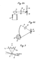
- a diffraction grating G is rotatable about an axis perpendicular to the plane of the sheet of paper of the drawing at the origin 0 of the coordinate system.
- a light beam L I incident on the diffraction grating makes an angle ⁇ with the Y axis
- the diffracted light L D from the diffraction grating makes the same angle a with the Y axis on the side opposite to the incident light.
- the surface of the diffraction grating coincides with the X axis
- the diffracted light that emerges from the monochromator is of the zeroth order, and the position of the diffraction grating corresponds to zero wavelength.
- the Wavelength ⁇ of the diffracted light (of the first order only) that emerges out of the monochromator is given as:
- the angle e is proportional to the amount of rotation of the motor
- the grating constant is the inverse of the number N per millimeter of the grooves or lines ruled on the diffraction grating.
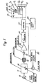
- a spectrophotometer comprising a light source 10, a monochromator 11, a sample cell 12 and a photodetector 13.
- the monochromator 11 includes a diffraction grating 14 which disperses the light from the source 10 into a series of wavelengths.
- a pulse motor M drives the diffraction grating 14 so that a selected one of the wavelengths is taken out of the monochromator.
- a sector gear 15 rotatable about an axis 16, and the diffraction grating 14 is mounted on the sector gear 15 with its axis coinciding with the axis 16 of the sector gear 15 for simultaneous rotation therewith.
- a pinion gear 17 meshes with the sector gear 15 and is driven directly by the pulse motor M.
- a photodetector 18 for detecting the wavelength origin is provided adjacent one side edge of the sector gear 15 so that when the diffraction grating 14 takes a position coinciding with the X axis of the coordinate system in Fig. 3, the photodetector 18 detects the side edge of the sector gear 15.
- the sample cell 12 contains a sample to be analyzed.
- the monochromatic light of a selected wavelength passes through the sample so as to be detected by the photodetector 13, which produces an output electrical signal in accordance with the intensity of the detected light.
- the output from the photodetector 13 is amplified by a preamplifier 19 and applied through an A/D converter 20 to a computer 21, which processes the data obtained by the measurement and at the same time controls the operation of the instrument.
- a display unit 22 indicates the result of the measurement.
- the computer 21 applies a signal in the form of pulses to a pulse motor driving circuit 23 to drive the pulse motor M for wavelength scanning of the monochromator.
- the pulses which corresponds to the amount 0 ⁇ of rotation of the motor in the previously given expression (1), are counted, so that the computer 21 calculates from the counted number of the pulses the wavelength ⁇ of the monochromatic light emerging from the monochromator in accordance with the expression (1).
- the grating pitch N is required as a parameter as shown in the expression.
- This parameter is input as three-bit data into the computer 21 through an input unit 24.
- the input unit 24 includes three switches Sl, S2 and S3 the stationary contacts of which are connected through pull-up resistors r1, r2 and r3, respectively, to a voltage source +V on one hand and to the computer 21 on the other, with the movable contacts of the switches being grounded as at E, so that the high or low level of the voltage at each of the stationary contacts of the switches is read into the computer 21.
- the switch S1 is provided for designation of addition (a positive sign) or subtraction (a negative sign), and the switches S2 and S3 correspond to numerical values 1 and 2, respectively, so that by combining the on or off condition of the three switches it is possible to set in the input unit seven (7) different values, that is, 0, +1, -1, +2, -2, +3 and -3 to be added to or subtracted from the nominal value N of the grating pitch.
- the computer 21 is so designed that when the data set in the input unit 24 is zero (0), the computer calculates the wavelength with the nominal grating pitch as the parameter N in the previously mentioned expression (1), and that when the data set in the input unit is ⁇ n, the computer calculates the wavelength with N ⁇ n as the parameter N in the expression (1).
- Diffraction gratings manufactured with a nominal grating pitch of N grooves or lines per millimeter may actually have a different pitch ranging, say, from N-3 to N+3.
- wavelength calibration is conducted by measuring a known sample for an emission line of a known wavelength on the assumption that the diffraction grating now in use has the nominal pitch, and calculating the actual grating pitch from the differ- rence between the known wavelength of the emission line and the measured wavelength thereof as indicated on the display unit, thereby to determine the parameter to be set in the input unit.
- the computer 21 operates in the following manner. There are two ways of calibration. In one of them the position of the diffraction grating for the zeroth-order light is first determined and the position thereof corresponding to the 656.1 nm emission line of the light from a deuterium lamp is measured for calibration. In the other method, the positions of the diffraction grating corresponding to the two emission lines of 656.1 nm and 486.0 nm of the light from a deuterium lamp are obtained for calibration.
- the position of the diffraction grating is roughly detected by the photodetector 18. Then a range adjacent the zeroth-order light is searched for a peak to determine the exact position of the diffraction grating for the zeroth-order light, and then a range adjacent the wavelength of 656.1 nm is searched for a peak to determine the position of the diffraction grating for the wavelength of 656.1 nm.
- the result of the calculation is indicated on the display unit 22, and in accordance with the indication, the switches Sl - S3 are operated to set in the input unit 24 the necessary data for calibration. After that, each time the apparatus is switched on, it is only necessary to determine the position of the diffraction grating for the zeroth-order light by peak searching. The computer will then reads the on or off conditions of the switches to calculate the wavelength of the monochromatic light now provided by the monochromator.
- both the positions of the emission lines of the wavelengths of 656.1 nm and 486.0 nm are determined. ln this case, the angles of rotation of the diffraction grating from the position thereof for the zeroth-order light to the positions thereof for the two emission lines can not be obtained, but only the difference angle ⁇ A 0 ⁇ of rotation of the diffraction grating between the positions thereof for the two emission lines can be obtained, so that it is impossible to obtain the actual number N' of the grooves of the diffraction grating from the difference angle ⁇ A 0 ⁇ .
- the wavelength is calculated from the counted number of the pulses applied to the pulse motor.
- wavelength calibration can be conducted with only one emission line of a known wavelength.
- a high degree of accuracy and precision can be attained in wavelength selection with a relatively simple mechanism for driving the diffraction grating.
Landscapes
- Physics & Mathematics (AREA)
- Spectroscopy & Molecular Physics (AREA)
- General Physics & Mathematics (AREA)
- Spectrometry And Color Measurement (AREA)
- Investigating Or Analysing Materials By Optical Means (AREA)
Applications Claiming Priority (2)
| Application Number | Priority Date | Filing Date | Title |
|---|---|---|---|
| JP145377/85 | 1985-07-02 | ||
| JP60145377A JPS626127A (ja) | 1985-07-02 | 1985-07-02 | 分光光度計 |
Publications (3)
| Publication Number | Publication Date |
|---|---|
| EP0207498A2 true EP0207498A2 (de) | 1987-01-07 |
| EP0207498A3 EP0207498A3 (en) | 1988-04-27 |
| EP0207498B1 EP0207498B1 (de) | 1993-09-29 |
Family
ID=15383824
Family Applications (1)
| Application Number | Title | Priority Date | Filing Date |
|---|---|---|---|
| EP86108951A Expired - Lifetime EP0207498B1 (de) | 1985-07-02 | 1986-07-01 | Spektrophotometer |
Country Status (5)
| Country | Link |
|---|---|
| US (1) | US4710024A (de) |
| EP (1) | EP0207498B1 (de) |
| JP (1) | JPS626127A (de) |
| CN (1) | CN1007010B (de) |
| DE (1) | DE3689085T2 (de) |
Cited By (4)
| Publication number | Priority date | Publication date | Assignee | Title |
|---|---|---|---|---|
| AU590089B2 (en) * | 1986-06-16 | 1989-10-26 | N.V. Philips Gloeilampenfabrieken | Method of and apparatus for spectroscopically analysing samples |
| EP0343659A1 (de) * | 1988-05-24 | 1989-11-29 | Anritsu Corporation | Spektrometer |
| EP0381053A1 (de) * | 1989-01-28 | 1990-08-08 | Shimadzu Corporation | Verfahren zum Betrieb eines Spektrophotometers |
| CN100545632C (zh) * | 2007-11-22 | 2009-09-30 | 中国科学院力学研究所 | 光纤光谱仪波长标定方法 |
Families Citing this family (8)
| Publication number | Priority date | Publication date | Assignee | Title |
|---|---|---|---|---|
| US4974209A (en) * | 1988-09-02 | 1990-11-27 | The Perkin-Elmer Corporation | Interactive smoothing system |
| US5023804A (en) * | 1989-05-23 | 1991-06-11 | The Perkin-Elmer Corporation | Method and apparatus for comparing spectra |
| CN102384785B (zh) * | 2010-09-01 | 2015-05-20 | 北京普源精电科技有限公司 | 一种分光光度计的全波段波长校正方法 |
| CN102798476A (zh) * | 2012-08-10 | 2012-11-28 | 浙江工业大学 | 测量高峰值功率单脉冲信号光谱的装置 |
| JP2014048143A (ja) * | 2012-08-31 | 2014-03-17 | Hitachi High-Technologies Corp | 分光光度計 |
| CN103323123A (zh) * | 2013-06-25 | 2013-09-25 | 长沙理工大学 | 一种全自动的光波波长的测量方法及装置 |
| JP6387610B2 (ja) * | 2013-12-27 | 2018-09-12 | ミツミ電機株式会社 | 生体情報測定装置 |
| CN110057787B (zh) * | 2019-05-17 | 2022-01-14 | 中世沃克(天津)科技发展股份有限公司 | 一种粉尘游离二氧化硅检测仪 |
Citations (4)
| Publication number | Priority date | Publication date | Assignee | Title |
|---|---|---|---|---|
| DE2754444B1 (de) * | 1977-12-07 | 1979-03-29 | Bodenseewerk Perkin Elmer Co | Spektrometer |
| GB2071313A (en) * | 1980-03-07 | 1981-09-16 | Perkin Elmer Corp | Spectrophotometer |
| JPS599523A (ja) * | 1982-07-09 | 1984-01-18 | Hitachi Ltd | 分光光度計の波長補正方式 |
| JPS59176633A (ja) * | 1983-03-25 | 1984-10-06 | Shimadzu Corp | 回析格子分光光度計 |
Family Cites Families (2)
| Publication number | Priority date | Publication date | Assignee | Title |
|---|---|---|---|---|
| US3563656A (en) * | 1966-04-15 | 1971-02-16 | Charles C Helms | Monochromator wavelength drives |
| JPS4982378A (de) * | 1972-12-11 | 1974-08-08 |
-
1985
- 1985-07-02 JP JP60145377A patent/JPS626127A/ja active Pending
-
1986
- 1986-05-22 CN CN86103504.6A patent/CN1007010B/zh not_active Expired
- 1986-07-01 DE DE86108951T patent/DE3689085T2/de not_active Expired - Fee Related
- 1986-07-01 EP EP86108951A patent/EP0207498B1/de not_active Expired - Lifetime
- 1986-07-02 US US06/881,331 patent/US4710024A/en not_active Expired - Lifetime
Patent Citations (4)
| Publication number | Priority date | Publication date | Assignee | Title |
|---|---|---|---|---|
| DE2754444B1 (de) * | 1977-12-07 | 1979-03-29 | Bodenseewerk Perkin Elmer Co | Spektrometer |
| GB2071313A (en) * | 1980-03-07 | 1981-09-16 | Perkin Elmer Corp | Spectrophotometer |
| JPS599523A (ja) * | 1982-07-09 | 1984-01-18 | Hitachi Ltd | 分光光度計の波長補正方式 |
| JPS59176633A (ja) * | 1983-03-25 | 1984-10-06 | Shimadzu Corp | 回析格子分光光度計 |
Non-Patent Citations (3)
| Title |
|---|
| ANALYTICAL CHEMISTRY, vol. 54, no. 11, September 1982, pages 1826-1828, Easton, PENNS., US; M.W. WARREN II et al.: "Wavelength accuracy of a microprocessor-controlled ultraviolet/visible monochromator" * |
| PATENT ABSTRACTS OF JAPAN, vol. 8, no. 97 (P-272)[1534], 8th May 1984; & JP 59009523 A (HITACHI SEISAKUSHO K.K.) 18-01-1984 * |
| PATENT ABSTRACTS OF JAPAN, vol. 9, no. 33 (P-334)[1756], 13th February 1985; & JP 59176633 A (SHIMAZU SEISAKUSHO K.K.) 06-10-1984 * |
Cited By (6)
| Publication number | Priority date | Publication date | Assignee | Title |
|---|---|---|---|---|
| AU590089B2 (en) * | 1986-06-16 | 1989-10-26 | N.V. Philips Gloeilampenfabrieken | Method of and apparatus for spectroscopically analysing samples |
| EP0343659A1 (de) * | 1988-05-24 | 1989-11-29 | Anritsu Corporation | Spektrometer |
| US4969740A (en) * | 1988-05-24 | 1990-11-13 | Anritsu Corporation | Spectrometer |
| EP0381053A1 (de) * | 1989-01-28 | 1990-08-08 | Shimadzu Corporation | Verfahren zum Betrieb eines Spektrophotometers |
| US5268737A (en) * | 1989-01-28 | 1993-12-07 | Shimidzu Corporation Of 1 | Method and apparatus for calibrating a spectrophotometer |
| CN100545632C (zh) * | 2007-11-22 | 2009-09-30 | 中国科学院力学研究所 | 光纤光谱仪波长标定方法 |
Also Published As
| Publication number | Publication date |
|---|---|
| CN1007010B (zh) | 1990-02-28 |
| EP0207498B1 (de) | 1993-09-29 |
| DE3689085T2 (de) | 1994-02-03 |
| DE3689085D1 (de) | 1993-11-04 |
| US4710024A (en) | 1987-12-01 |
| EP0207498A3 (en) | 1988-04-27 |
| JPS626127A (ja) | 1987-01-13 |
| CN86103504A (zh) | 1986-12-31 |
Similar Documents
| Publication | Publication Date | Title |
|---|---|---|
| US4710024A (en) | Spectrophotometer | |
| DE2823060C2 (de) | ||
| US4077129A (en) | Portable, lightweight measuring instrument | |
| EP0080699B1 (de) | Densitometer | |
| EP2385354B1 (de) | Optischer codierer mit kontaminations- und fehlerresistenter signalverarbeitung | |
| EP0039082B1 (de) | Verfahren und Einrichtung zum Messen der Verschiebung zwischen einer Kodierplatte und einer Sensoranordnung | |
| EP0169657A2 (de) | Kontaktloser Wellenwinkeldetektor | |
| EP0381053A1 (de) | Verfahren zum Betrieb eines Spektrophotometers | |
| JPH06258102A (ja) | 測定装置 | |
| EP0790484A2 (de) | Korrekturmechanismus für den horizontalen Positionsfehler in einer elektronischen Waage | |
| JPS58147611A (ja) | 測定量測定方法及び装置 | |
| GB2009922A (en) | Gloss measurement | |
| EP0044823A2 (de) | Mikrometer mit digitaler Leseeinrichtung | |
| US3076374A (en) | System and mechanism for measuring displacements | |
| WO1993021639A1 (en) | X-y table apparatus | |
| US4505042A (en) | Dimension measuring instrument | |
| US4869110A (en) | Laser strain extensometer for material testing | |
| US4636630A (en) | Photoelectric type displacement detection apparatus | |
| Kint et al. | A Computer Controlled Raman Spectrometer System | |
| US4187612A (en) | Height gage | |
| GB2067283A (en) | Determining relative movement | |
| US3363257A (en) | Recorder with edge-lighted scales and fluorescent indicator | |
| JPH05196451A (ja) | 測長または測角装置 | |
| EP0229602A1 (de) | Reflektometrische Methode der Messung und Vorrichtung zur Durchführung dieser Methode | |
| JPS6139285Y2 (de) |
Legal Events
| Date | Code | Title | Description |
|---|---|---|---|
| PUAI | Public reference made under article 153(3) epc to a published international application that has entered the european phase |
Free format text: ORIGINAL CODE: 0009012 |
|
| AK | Designated contracting states |
Kind code of ref document: A2 Designated state(s): DE GB |
|
| PUAL | Search report despatched |
Free format text: ORIGINAL CODE: 0009013 |
|
| AK | Designated contracting states |
Kind code of ref document: A3 Designated state(s): DE GB |
|
| 17P | Request for examination filed |
Effective date: 19881004 |
|
| 17Q | First examination report despatched |
Effective date: 19900613 |
|
| GRAA | (expected) grant |
Free format text: ORIGINAL CODE: 0009210 |
|
| AK | Designated contracting states |
Kind code of ref document: B1 Designated state(s): DE GB |
|
| REF | Corresponds to: |
Ref document number: 3689085 Country of ref document: DE Date of ref document: 19931104 |
|
| PGFP | Annual fee paid to national office [announced via postgrant information from national office to epo] |
Ref country code: GB Payment date: 19940621 Year of fee payment: 9 |
|
| PGFP | Annual fee paid to national office [announced via postgrant information from national office to epo] |
Ref country code: DE Payment date: 19940622 Year of fee payment: 9 |
|
| PLBE | No opposition filed within time limit |
Free format text: ORIGINAL CODE: 0009261 |
|
| STAA | Information on the status of an ep patent application or granted ep patent |
Free format text: STATUS: NO OPPOSITION FILED WITHIN TIME LIMIT |
|
| 26N | No opposition filed | ||
| PG25 | Lapsed in a contracting state [announced via postgrant information from national office to epo] |
Ref country code: GB Effective date: 19950701 |
|
| GBPC | Gb: european patent ceased through non-payment of renewal fee |
Effective date: 19950701 |
|
| PG25 | Lapsed in a contracting state [announced via postgrant information from national office to epo] |
Ref country code: DE Effective date: 19960402 |