EP0207247A2 - Méthode et dispositif d'enduction de tubes à lampes fluorescentes et lampe fluorescente obtenue - Google Patents
Méthode et dispositif d'enduction de tubes à lampes fluorescentes et lampe fluorescente obtenue Download PDFInfo
- Publication number
- EP0207247A2 EP0207247A2 EP86105583A EP86105583A EP0207247A2 EP 0207247 A2 EP0207247 A2 EP 0207247A2 EP 86105583 A EP86105583 A EP 86105583A EP 86105583 A EP86105583 A EP 86105583A EP 0207247 A2 EP0207247 A2 EP 0207247A2
- Authority
- EP
- European Patent Office
- Prior art keywords
- phosphor
- lamp tube
- fluorescent lamp
- particulate
- applying
- Prior art date
- Legal status (The legal status is an assumption and is not a legal conclusion. Google has not performed a legal analysis and makes no representation as to the accuracy of the status listed.)
- Granted
Links
- 238000000576 coating method Methods 0.000 title claims abstract description 46
- 238000000034 method Methods 0.000 title claims abstract description 18
- 239000011248 coating agent Substances 0.000 title claims description 28
- OAICVXFJPJFONN-UHFFFAOYSA-N Phosphorus Chemical compound [P] OAICVXFJPJFONN-UHFFFAOYSA-N 0.000 claims abstract description 102
- 239000011521 glass Substances 0.000 claims abstract description 69
- 239000002245 particle Substances 0.000 claims abstract description 49
- 239000011230 binding agent Substances 0.000 claims abstract description 26
- 238000000151 deposition Methods 0.000 claims abstract description 24
- 230000008021 deposition Effects 0.000 claims abstract description 20
- 239000000463 material Substances 0.000 claims description 30
- 239000011236 particulate material Substances 0.000 claims description 15
- 230000004888 barrier function Effects 0.000 claims description 4
- 238000010438 heat treatment Methods 0.000 claims description 3
- 229910001220 stainless steel Inorganic materials 0.000 claims description 3
- 239000010935 stainless steel Substances 0.000 claims description 3
- 229920006395 saturated elastomer Polymers 0.000 claims description 2
- 238000004924 electrostatic deposition Methods 0.000 abstract description 8
- 239000000843 powder Substances 0.000 description 11
- 238000004519 manufacturing process Methods 0.000 description 9
- XOLBLPGZBRYERU-UHFFFAOYSA-N tin dioxide Chemical compound O=[Sn]=O XOLBLPGZBRYERU-UHFFFAOYSA-N 0.000 description 7
- 229910001887 tin oxide Inorganic materials 0.000 description 7
- 239000000203 mixture Substances 0.000 description 5
- XKRFYHLGVUSROY-UHFFFAOYSA-N Argon Chemical compound [Ar] XKRFYHLGVUSROY-UHFFFAOYSA-N 0.000 description 4
- 238000010420 art technique Methods 0.000 description 4
- 230000008569 process Effects 0.000 description 4
- XLYOFNOQVPJJNP-UHFFFAOYSA-N water Substances O XLYOFNOQVPJJNP-UHFFFAOYSA-N 0.000 description 4
- 238000005452 bending Methods 0.000 description 3
- 230000007246 mechanism Effects 0.000 description 3
- 230000000717 retained effect Effects 0.000 description 3
- RYGMFSIKBFXOCR-UHFFFAOYSA-N Copper Chemical compound [Cu] RYGMFSIKBFXOCR-UHFFFAOYSA-N 0.000 description 2
- 229910052786 argon Inorganic materials 0.000 description 2
- 230000008901 benefit Effects 0.000 description 2
- 239000004020 conductor Substances 0.000 description 2
- 238000010276 construction Methods 0.000 description 2
- 229910052802 copper Inorganic materials 0.000 description 2
- 239000010949 copper Substances 0.000 description 2
- 238000010586 diagram Methods 0.000 description 2
- 230000000694 effects Effects 0.000 description 2
- 238000009503 electrostatic coating Methods 0.000 description 2
- 239000007789 gas Substances 0.000 description 2
- QSHDDOUJBYECFT-UHFFFAOYSA-N mercury Chemical compound [Hg] QSHDDOUJBYECFT-UHFFFAOYSA-N 0.000 description 2
- 239000002002 slurry Substances 0.000 description 2
- 239000000725 suspension Substances 0.000 description 2
- BTBUEUYNUDRHOZ-UHFFFAOYSA-N Borate Chemical compound [O-]B([O-])[O-] BTBUEUYNUDRHOZ-UHFFFAOYSA-N 0.000 description 1
- 239000000654 additive Substances 0.000 description 1
- 230000002411 adverse Effects 0.000 description 1
- 239000007900 aqueous suspension Substances 0.000 description 1
- 238000007664 blowing Methods 0.000 description 1
- 150000001642 boronic acid derivatives Chemical class 0.000 description 1
- -1 calcium borate Chemical class 0.000 description 1
- 239000003575 carbonaceous material Substances 0.000 description 1
- 230000015556 catabolic process Effects 0.000 description 1
- 239000012141 concentrate Substances 0.000 description 1
- 239000002270 dispersing agent Substances 0.000 description 1
- 230000008030 elimination Effects 0.000 description 1
- 238000003379 elimination reaction Methods 0.000 description 1
- 238000005265 energy consumption Methods 0.000 description 1
- 230000003628 erosive effect Effects 0.000 description 1
- 230000005484 gravity Effects 0.000 description 1
- 238000003780 insertion Methods 0.000 description 1
- 230000037431 insertion Effects 0.000 description 1
- 229910052743 krypton Inorganic materials 0.000 description 1
- DNNSSWSSYDEUBZ-UHFFFAOYSA-N krypton atom Chemical compound [Kr] DNNSSWSSYDEUBZ-UHFFFAOYSA-N 0.000 description 1
- 238000012423 maintenance Methods 0.000 description 1
- 229910052753 mercury Inorganic materials 0.000 description 1
- 239000011368 organic material Substances 0.000 description 1
- 229920000620 organic polymer Polymers 0.000 description 1
- 230000008520 organization Effects 0.000 description 1
- 239000013618 particulate matter Substances 0.000 description 1
- 239000006223 plastic coating Substances 0.000 description 1
- 239000002491 polymer binding agent Substances 0.000 description 1
- 230000009467 reduction Effects 0.000 description 1
- 238000007789 sealing Methods 0.000 description 1
- 238000000926 separation method Methods 0.000 description 1
- 239000007858 starting material Substances 0.000 description 1
- VLCLHFYFMCKBRP-UHFFFAOYSA-N tricalcium;diborate Chemical compound [Ca+2].[Ca+2].[Ca+2].[O-]B([O-])[O-].[O-]B([O-])[O-] VLCLHFYFMCKBRP-UHFFFAOYSA-N 0.000 description 1
Images


Classifications
-
- H—ELECTRICITY
- H01—ELECTRIC ELEMENTS
- H01J—ELECTRIC DISCHARGE TUBES OR DISCHARGE LAMPS
- H01J9/00—Apparatus or processes specially adapted for the manufacture, installation, removal, maintenance of electric discharge tubes, discharge lamps, or parts thereof; Recovery of material from discharge tubes or lamps
- H01J9/20—Manufacture of screens on or from which an image or pattern is formed, picked up, converted or stored; Applying coatings to the vessel
- H01J9/22—Applying luminescent coatings
- H01J9/221—Applying luminescent coatings in continuous layers
- H01J9/225—Applying luminescent coatings in continuous layers by electrostatic or electrophoretic processes
-
- B—PERFORMING OPERATIONS; TRANSPORTING
- B05—SPRAYING OR ATOMISING IN GENERAL; APPLYING FLUENT MATERIALS TO SURFACES, IN GENERAL
- B05B—SPRAYING APPARATUS; ATOMISING APPARATUS; NOZZLES
- B05B5/00—Electrostatic spraying apparatus; Spraying apparatus with means for charging the spray electrically; Apparatus for spraying liquids or other fluent materials by other electric means
- B05B5/08—Plant for applying liquids or other fluent materials to objects
Definitions
- This invention relates to fluorescent lamps and the manufacture of fluorescent lamps, and, more particularly, to a method and apparatus for applying a layer of particulate material to the inside of a fluorescent lamp bulb by electrostatic deposition and the resulting fluorescent lamp.
- phosphor coatings are typically applied as a suspension of particulate material in a slurry including an organic binder.
- the organic binder serves the function of holding the phosphor particles to the glass bulb surface during the manufacturing of the bulb.
- the bulbs are lehred at a high temperature to vaporize the organic binder and bond the phosphor particles to the glass bulb surface and to other phosphor particles to form a uniform, well-bonded coating on the fluorescent lamp bulb.
- This technique requires heating of the lamp bulb to a temperature which would cause the lamp glass to soften.
- straight line fluorescent lamps are conventionally rotated during the lehring process so that the gravitational effects are averaged and the lamp maintains a straight shape.
- U-shaped fluorescent lamps having both sets of lamp terminals at the same end of the lamp raise a difficulty with respect to lamp coating and lehring which is not experienced in manufacturing straight fluorescent lamps.
- the phosphor coatings are typically applied as water suspensions containing organic polymer binders which act as dispersing agents to provide smooth coating appearance.
- the binders must be removed prior to sealing of the lamp and filling with the typical fluorescent lamp atmospheres, because the organic materials of the binder are incompatible with the fluorescent lamp atmosphere and tend to cause darkening and loss of lamp efficacy in lumens per watt over the life of the lamp.
- the binders typically are removed by baking at elevated temperatures, i.e.
- a tin oxide starting strip is applied to an interior surface of the fluorescent lamp extending generally from one electrode around the bend of the lamp to the opposite electrode in order to assist in starting of the lamp. If this coating is applied prior to lamp bending, difficulties are experienced in maintaining electrical continuity of the starter strip following bending of the glass tube due to the strain on the glass and therefore on the starting strip during bending. Therefore, the starting strip is typically applied after the glass tube has been bent into the desired U-shape.
- a difficulty experienced when using tin oxide as the starting strip results from the use of an insulating barrier coating on the tin oxide coating to overcome the poor adherence of phosphors to tin oxide and the tendency of the tin oxide to darken with exposure to the atmosphere inside the fluorescent lamp.
- certain types of borates e.g. calcium borate, are included within the binder material. Removal of the binders from the lamp following deposition of the phosphors requires a still higher lehring temperature when additional borate additives are used, which increases the risk of sa g in the U-shaped lamps.
- a technique of applying phosphor coatings and bonding the coatings to the lamp glass without requiring high temperature lehring is required.
- An object of the present invention is to provide a U-shaped fluorescent lamp having no binder residue in the phosphor coating and a method and apparatus for applying phosphor coatings to the interior surfaces of fluorescent lamp tubes without requiring the use of binder materials whose removal from the lamp requires high temperature lehring.
- a more specific object of the present invention is to provide an electrostatic coating technique for applying phosphor layers to the interior surfaces of a U-shaped fluorescent lamp.
- the present invention includes an electrostatic coating apparatus having one electrode positioned outside the glass tube and at a predetermined position relative to a pair of second electrodes placed inside the glass tube during the coating process; each of the second electrodes having a nozzle attached thereto with passages therethrough for the delivery of phosphor coating material to the interior of the glass envelope and a tip for forming a corona: and connections to a high voltage d-c electrical power supply for applying voltage of a first polarity to the first electrode and voltage of a second polarity to the second electrodes; such that a field is created between the electrode tips which causes the glass tube to become electrically charged with one polarity and the particles of phosphor material to become oppositely charged, so that the phosphor particles are attracted to the interior surface of the glass tube and adhere thereto.
- the present invention further comprises a method of depositing phosphor coatings on U-shaped fluorescent lamps and a U-shaped fluorescent lamp having phosphor coating devoid of organic binder residue.
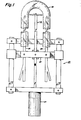
- the apparatus of the present invention comprises equipment for coating the interior surface of a fluorescent lamp glass tube while the tube is suspended in a suitable holding device (not shown).
- the coating apparatus includes a high voltage electrode 10 and a pair of phosphor supply tubes 26, 28 secured to a movement mechanism 25 for moving the electrode 10 and supply tubes 26, 28 relative to the glass tube 20 at a controllable, constant rate.
- the movement mechanism may include hydraulic, compressed air or electric motor means 27 to provide the controlled movement.
- the electrode 10 and supply tubes 26, 28 are secured to suitable holders 23 for movement together during phosphor deposition. As shown in more detail in FIG.
- a high voltage electrode 10 comprising conductive rod 12 and conductive tip member 14 is disposed so that the points 16, 18 at the respective ends of the conductive member 14 are in close proximity to the glass tube 20 but are not in contact therewith.
- the rod 12 is connected via a suitable conductor shown schematically as 22 to a high voltage d-c power supply 24.
- the present apparatus further includes supply tubes 26 and 28 for receiving via tubes 25, 27, respectively, a mixture of dry air and powder from a powder supply hopper 29 of conventional design, such as a fluidized bed, and conveying the mixture of dry air and powder to the interior 30 of the glass tube 20 for coating the interior surface 32 thereof.
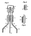
- the nozzles 34 are both of a similar construction, one of which is shown enlarged in FIG. 3.
- the tube 26 is connected to a nozzle 34 for example by threads 38.
- the nozzle 34 includes a plurality of passages 39 cut through the closed end wall 47 at a predetermined angle with respect to the nozzle centerline 40 to concentrate the phosphor powder in the corona region 42 surrounding tip 44.
- the angle is determined experimentally to provide optimum powder flow from the nozzle past the tip 44 and through the corona region 42 into the interior of the glass tube for deposition upon the surface 32, shown in FIG. 2.
- the angle e determines the distance of travel of the phosphor particles before deposition on the glass surface.
- the passages 39 are typically 50-100 milsvin diameter, substantially larger than the particle size of the phosphor being deposited.
- the passages 39 may be cut with a slight spiral to cause the phosphor particles to swirl as they pass over the tip.
- the tube 26 may be a copper tube having a plastic coating to prevent erosion of the tubing by fluorescent phosphor particles supplied to the interior of the lamp, or alternatively the tube 26 may be a stainless steel tube requiring no inner lining.
- the tip 34 is preferably of stainless steel.
- the rod 12 and tip member 14 are preferably of copper or other suitable conductive material. Although the conductive member 14 is shown to be in the plane of the U-shaped glass tube 20, the rod 12 and tip member 14 may be offset, e.g., above the plane of the paper as shown in FIG.
- the tip member 14 may be positioned to ensure deposition of phosphor powder over the entire surface of the curve in the lamp if required for particular phosphors.
- FIG. 4 An alternative embodiment is illustrated schematically in FIG. 4 for the application of phosphor coatings to a different type of U-shaped fluorescent lamp.
- the lamp tube 50 is a glass fluorescent tube used in twin-tube lamps of the type sold by the General Electric Company under the trademark MOD-U-LINEo having a sharp U-bend and smaller diameter, typically T-5 approximately 5/8 inchvdiameter, than the lamp shown in FIG. 2.
- the central rod 52 has a tip 54 attached thereto generally aligned with the axis 56 of the rod 52.
- the pair of supply tubes 58 and 60 are configured to have bends 62, 64 and 66, 68, respectively, to position the supply tubes properly for insertion into the legs 74, 76 of the U-shaped lamp tube 50.
- the supply tubes have nozzles 70, 72 of a construction similar to nozzle 34, described above, but of smaller diameter connected respectively thereto.
- the materials of the rod 52 and the supply tubes 58 and 60 and the nozzle 70 and 72 are as described above withrespect to the embodiment of FIG. 2.
- the rod 52 and tip 54 could be offset from the plane of the glass tube 50, rather than being in the plane of the tube 50, so that the tip 54 could be positioned adjacent the U-shaped bend rather than within the U-shaped bend.
- the tip 54 could be provided by turning the tip member 14 perpendicular to the plane of the glass tube and positioning one of the tips 16 or 18 in close proximity to the bend of the tube 50 of FIG. 2.
- the present invention provides a method of phosphor deposition as shown in the block diagram of FIG. 7, as follows: the glass fluorescent tube is bent into the U-shaped configuration while heated. While the glass tube is still hot, it is loaded into a suitable lamp holding mechanism for deposition of the phosphor coatings. Alternatively, the bulbs may be . allowed to cool and then be reheated. The heating removes moisture from the surface of the glass tubes and thereby reduces surface conductivity, which would interfere with the application of charge to the glass surface.
- the supply tubes 26 and 28 are inserted into the legs of the U-shaped lamp, and the electrode tips 16 and 18 are positioned adjacent the glass tube wall and slightly above and generally adjacent the position of the tips of the nozzles. The supply tubes 26 and 28 are connected to electrical ground.
- the power supply 24 connected to the rod 12 supplies a D.C. voltage in the range of 20 to 50 kV.
- the exact setting for a particular deposition is established by raising the voltage to a level at which breakdown occurs in air and then reducing the voltage level slightly to avoid arcing. This spacin is typically in the range of about 0.50 inchyto a out 2.00 inches (5.08cm).
- a supply of dry air or other suitable gas is provided to the phosphor feed hopper to entrain particulate matter in a stream flowing vertically upward through the tubes 26, 28 into the bight of the glass tube. The phosphor particles are charged as they pass through the corona region 42.
- the phosphor particle size is typically 3.0 to 15.0 microns plus or minus 15 percent at the particle's maximum dimension, which is standard for fluorescent phosphor particle size.
- the passages 39 are thus much larger in diameter than the particles and do not significantly affect particle velocity through the nozzles.
- the phosphor particles travel about four to six inches beyond the openings 45 before contacting the glass tube wall.
- the powder supply nozzles and the electrode member 14 are moved vertically downward at a rate determined by the desired thickness of deposition upon the interior surface of the glass wall, e.g., at about 5 inches per second for coating the T-12 or approximately 1.5 inch diameter tube shown in the FIG. 2 embodiment.
- the glass tube could be moved while the powder supply tubes and the electrode are kept fixed.
- a second step of electrostatic deposition may be employed by moving the nozzels and electrode 10 back to their beginning positions and repeating the procedure described above. If a different phosphor is to be used for the second deposition, the appropriate supply hopper would be connected to tubes 25, 27 prior to the beginning of the second deposition step. Following electrostatic deposition of phosphors the coated bulb is cooled in air. Whether one layer or two or more layers have been deposited, the phosphor coating is humidified by blowing saturated air into the interior of the tube so that moisture is picked up on the surfaces of the particulate phosphor material.
- a fluorescent lamp stem including an electrode and supporting leads sealed in the glass stem is attached to each respective end of the U-shaped lamp tube.
- a suitable quantity of mercury is disposed in the lamp to provide a mercury vapor discharge path in the lamp, and a gas fill, such as argon or a mixture of krypton and argon, is added.
- argon or a mixture of krypton and argon
- the glass tube is maintained at a temperature range from about 150°C to about 500°C at which it is electrically conductive, so that a current flow of approximately 2.5 milliamperes flows through the rod 12 and from the tips 16 and 18 through the glass of the lamp tube and the phosphor particles in the interior of.the glass to the respective tips 44 of the nozzles 34.
- the powder being blown through the respective supply tubes into the glass bulb picks up a negative charge as it passes the corona point.
- the current flowing through the glass wall causes the glass to accumulate a positive charge. As shown greatly enlarged in FIG. 5, the glass wall 20 accumulates a positive charge, shown at 80, and the phosphor particles 82 exhibit a negative charge.
- the glass tube is isolated from the electrical system and from electrical ground, the positive charge is retained, and therefore the particulate phosphor is caused to adhere to the glass surface.
- This retained charge will dissipate over time, but if properly isolated will retain adequate charge for a period of approximately 12 hours, so that the particulate phosphor can be bonded to the glass surface while it is still being held in place by the electrical attraction.
- the charge on the powder in the coating is retained because of the low conductivity of the powder. This allows sufficient time for the humidification and lehring of the coated lamp.
- a second layer 83 of phosphor particles 84 of substantially different size than the particles 82 is deposited over the first layer 81.
- Humidification causes the layers 81, 83 of phosphor particles to be densified due to the fact that moisture on the surfaces of the individual particles causes the phosphor particles to shift slightly relative to each other to reduce spaces between particles and become more closely packed to the surface of the glass by the mutual attraction of the electrostatic charge. This improves the uniformity of the phosphor coatings on the lamp glass.
- the particulate layers will be maintained generally separate along a line shown at 86 at a position generally corresponding to the thickness of the first particulate layer 81 from the surface of the glass wall. Upon lehring the particles of phosphor are bound together to the glass surface to form uniform, bonded layers as shown in FIG. 6.
- a lower lehring temperature may be employed following the electrostatic deposition according to the present invention than is employed in prior art slurry deposition, because no organic binder containing carbon materials is used to initially bond the phosphor coatings to the glass.
- the lower lehring temperature 475°C to 600 * C, which would be inadequate to burn out organic binder materials, is adequate to cause phosphor bonding and removal of water but is not high enough to cause softening of the glass. Therefore, the sag which is experienced at high temperature lehring is avoided for U-shaped lamps made according to the present invention, so that no distortion of lamp shape is caused by the lehring step.
- An additional advantage of the present invention is that only a limited amount of moisture is used in the humidifying of the lamps, thereby reducing the quantity of water which must be removed by lehring, so that the time required for lehring is less than that required by prior art techniques even though the lehring temperature is lower.
- the electrostatic deposition process of the present invention is not adversely affected by the presence of a starting strip on the interior surface of the glass tube.
- the present invention performs phosphor deposition with no reduction of adherence of the phosphor to the starting stripe or insulating barrier layer.
- the present invention facilitates deposition of phosphor mixtures which may include several particle sizes, because no gravitational separation would occur and the electrostatic bonding of phosphor particles to the glass surface would not be affected by particle size.
- Phosphors which are difficult to keep in suspension or are incompatible with an organic binder are readily applied by the electrostatic deposition process of the present invention because of the elimination of the binder.
- the lamps of the present invention include both types of U-shaped fluorescent lamps shown in Fig. 2 and Fig. 4 having one or more layers of phosphor particles as shown in Figs. 5 and 6 bonded thereto and completely devoid of any residue of organic binder.
- Each phosphor layer may include a mixture of more than one particle size or may be a single particle size.
- the lamps may include an internal starting strip with insulating barrier or may have no internal starting aid.
Landscapes
- Engineering & Computer Science (AREA)
- Manufacturing & Machinery (AREA)
- Formation Of Various Coating Films On Cathode Ray Tubes And Lamps (AREA)
- Application Of Or Painting With Fluid Materials (AREA)
- Electrostatic Spraying Apparatus (AREA)
- Vessels And Coating Films For Discharge Lamps (AREA)
Applications Claiming Priority (4)
| Application Number | Priority Date | Filing Date | Title |
|---|---|---|---|
| US74046085A | 1985-06-03 | 1985-06-03 | |
| US740460 | 1985-06-03 | ||
| US06/811,891 US4597984A (en) | 1985-06-03 | 1985-12-20 | Method and apparatus for coating fluorescent lamp tubes |
| US811891 | 1985-12-20 |
Publications (3)
| Publication Number | Publication Date |
|---|---|
| EP0207247A2 true EP0207247A2 (fr) | 1987-01-07 |
| EP0207247A3 EP0207247A3 (en) | 1987-08-26 |
| EP0207247B1 EP0207247B1 (fr) | 1990-09-05 |
Family
ID=27113682
Family Applications (1)
| Application Number | Title | Priority Date | Filing Date |
|---|---|---|---|
| EP86105583A Expired - Lifetime EP0207247B1 (fr) | 1985-06-03 | 1986-04-23 | Méthode et dispositif d'enduction de tubes à lampes fluorescentes et lampe fluorescente obtenue |
Country Status (6)
| Country | Link |
|---|---|
| US (1) | US4597984A (fr) |
| EP (1) | EP0207247B1 (fr) |
| JP (1) | JPS61284027A (fr) |
| BR (1) | BR8601989A (fr) |
| DE (1) | DE3673890D1 (fr) |
| MX (1) | MX164546B (fr) |
Families Citing this family (10)
| Publication number | Priority date | Publication date | Assignee | Title |
|---|---|---|---|---|
| US5107167A (en) * | 1990-06-19 | 1992-04-21 | Gte Products Corporation | Incandescent bug lamp with cadmium-free powder coating |
| DE4119853C2 (de) * | 1991-06-06 | 1994-01-27 | Prolux Maschinenbau Gmbh | Verfahren und Vorrichtung zur gleichmäßigen Innenbeschichtung von mäanderförmigen Einrohrglasentladungsgefäßen mit einer Leuchtstoff-Suspension |
| US5252887A (en) * | 1992-01-21 | 1993-10-12 | General Electric Company | Environmentally safe pink lamp |
| US5314723A (en) * | 1992-06-09 | 1994-05-24 | Gte Products Corporation | Method of coating phosphors on fluorescent lamp glass |
| US5362524A (en) * | 1992-12-29 | 1994-11-08 | Gte Products Corporation | Method for coating asymmetric glass envelope for lamp by electrostatic coating |
| US5344667A (en) * | 1993-02-23 | 1994-09-06 | Rockwell International Corporation | Method and apparatus for manufacturing serpentine avionics fluorescent tubes with enhanced uniformity of luminance and chromaticity |
| US6265821B1 (en) | 1993-02-23 | 2001-07-24 | Rockwell Collins, Inc. | Serpentine avionics fluorescent tube with uniformity of luminance and chromaticity |
| US6363606B1 (en) * | 1998-10-16 | 2002-04-02 | Agere Systems Guardian Corp. | Process for forming integrated structures using three dimensional printing techniques |
| US6531814B1 (en) | 2000-02-17 | 2003-03-11 | General Electric Company | Fluorescent lamp coating and coating recycling method |
| US7163722B2 (en) * | 2003-12-19 | 2007-01-16 | Lcd Lighting, Inc. | Device and method for coating serpentine fluorescent lamps |
Citations (4)
| Publication number | Priority date | Publication date | Assignee | Title |
|---|---|---|---|---|
| FR2328277A1 (fr) * | 1975-10-17 | 1977-05-13 | Philips Nv | Procede pour recouvrir la paroi interieure d'une lampe a decharge dans la vapeur de mercure a basse pression de materiau |
| JPS57124829A (en) * | 1981-01-26 | 1982-08-03 | Mitsubishi Electric Corp | Formation of phosphor layer |
| EP0118251A2 (fr) * | 1983-03-08 | 1984-09-12 | THORN EMI plc | Méthodes d'enduction électrostatique de matière luminescente sur les parois des lampes fluorescentes et lampes ainsi enduites |
| EP0140448A1 (fr) * | 1983-10-26 | 1985-05-08 | Koninklijke Philips Electronics N.V. | Méthode de formation d'une couche luminescente sur un support et lampe à vapeur de mercure à basse pression ayant une couche appliquée sur un support par cette méthode |
Family Cites Families (12)
| Publication number | Priority date | Publication date | Assignee | Title |
|---|---|---|---|---|
| CA478893A (fr) * | 1951-11-27 | Canadian Westinghouse Company | Appareils et methodes d'enduisage electrostatique | |
| CA454727A (fr) * | 1949-02-22 | Canadian Westinghouse Company | Methode et appareil electrostatique a enduire | |
| GB661412A (en) * | 1949-02-01 | 1951-11-21 | British Thomson Houston Co Ltd | Improvements relating to the production of fluorescent electric discharge lamps |
| US3126300A (en) * | 1960-09-02 | 1964-03-24 | Device for coating the inner surfaces | |
| JPS49123368U (fr) * | 1973-02-26 | 1974-10-22 | ||
| JPS5822264B2 (ja) * | 1976-05-14 | 1983-05-07 | 松下電子工業株式会社 | けい光ランプの静電塗装方法 |
| US4121132A (en) * | 1977-09-28 | 1978-10-17 | Westinghouse Electric Corp. | Phosphor coating method and resulting fluorescent lamp |
| JPS5564864A (en) * | 1978-11-09 | 1980-05-15 | Matsushita Electronics Corp | Electrostatic coating |
| HU178517B (en) * | 1978-12-12 | 1982-05-28 | Egyesuelt Izzolampa | Method for improving bulb coating of electric light sources |
| JPS57119878A (en) * | 1981-01-19 | 1982-07-26 | Toshiba Corp | Method for electrostatic painting of non-linear tube bulb |
| US4540915A (en) * | 1981-04-30 | 1985-09-10 | Hitachi, Ltd. | Fluorescent lamp and phosphor coating composition used therefor |
| JPS59149647A (ja) * | 1983-02-04 | 1984-08-27 | Toshiba Corp | 高圧放電灯 |
-
1985
- 1985-12-20 US US06/811,891 patent/US4597984A/en not_active Expired - Lifetime
-
1986
- 1986-03-14 MX MX1889A patent/MX164546B/es unknown
- 1986-03-18 JP JP61058483A patent/JPS61284027A/ja active Granted
- 1986-04-18 BR BR8601989A patent/BR8601989A/pt not_active IP Right Cessation
- 1986-04-23 EP EP86105583A patent/EP0207247B1/fr not_active Expired - Lifetime
- 1986-04-23 DE DE8686105583T patent/DE3673890D1/de not_active Expired - Fee Related
Patent Citations (4)
| Publication number | Priority date | Publication date | Assignee | Title |
|---|---|---|---|---|
| FR2328277A1 (fr) * | 1975-10-17 | 1977-05-13 | Philips Nv | Procede pour recouvrir la paroi interieure d'une lampe a decharge dans la vapeur de mercure a basse pression de materiau |
| JPS57124829A (en) * | 1981-01-26 | 1982-08-03 | Mitsubishi Electric Corp | Formation of phosphor layer |
| EP0118251A2 (fr) * | 1983-03-08 | 1984-09-12 | THORN EMI plc | Méthodes d'enduction électrostatique de matière luminescente sur les parois des lampes fluorescentes et lampes ainsi enduites |
| EP0140448A1 (fr) * | 1983-10-26 | 1985-05-08 | Koninklijke Philips Electronics N.V. | Méthode de formation d'une couche luminescente sur un support et lampe à vapeur de mercure à basse pression ayant une couche appliquée sur un support par cette méthode |
Non-Patent Citations (1)
| Title |
|---|
| Patent Abstracts of Japan,vol.6,no.222 (E-140)(1100),06 november 1982 & JP-A-57 124829 * |
Also Published As
| Publication number | Publication date |
|---|---|
| DE3673890D1 (de) | 1990-10-11 |
| EP0207247A3 (en) | 1987-08-26 |
| MX164546B (es) | 1992-08-26 |
| JPS61284027A (ja) | 1986-12-15 |
| JPH0588494B2 (fr) | 1993-12-22 |
| BR8601989A (pt) | 1987-01-06 |
| US4597984A (en) | 1986-07-01 |
| EP0207247B1 (fr) | 1990-09-05 |
Similar Documents
| Publication | Publication Date | Title |
|---|---|---|
| US4597984A (en) | Method and apparatus for coating fluorescent lamp tubes | |
| US2048651A (en) | Method of and apparatus for producing fibrous or filamentary material | |
| US4230068A (en) | Apparatus used in continuous process for electrostatic coating with pulverized material | |
| CA2097625C (fr) | Methode servant a appliquer des luminophores sur du verre pour lampe fluorescente | |
| US2571608A (en) | Method and apparatus for connecting articles with a graded coating of glass | |
| EP0510128A1 (fr) | Formation de films de silicium depose sous forme d'aerosol | |
| US5902464A (en) | Apparatus for depositing cathode material on a wire cathode | |
| US2626874A (en) | Method for forming silica and for coating lamp bulbs | |
| US4099080A (en) | Incandescent lamp with improved coating and method | |
| US4188413A (en) | Electrostatic-fluidized bed coating of wire | |
| US2806444A (en) | Silica coating apparatus for incandescent lamp bulbs | |
| US1698845A (en) | Method of dry-coating lamp bulbs | |
| US4440350A (en) | Apparatus and method for coating with an atomizable material | |
| CA1299450C (fr) | Methode et appareil de revetement de tubes fluorescents | |
| US2608176A (en) | Apparatus for electrostatically coating articles | |
| US2604870A (en) | Electrostatic coating apparatus | |
| CA1088814A (fr) | Methode d'application d'un materiau luminescent sur la paroi interieure d'une lampe a arc a vapeur de mercure | |
| JP2000327359A (ja) | 光ファイバの製造方法および光ファイバ用母材の保管装置 | |
| US3358639A (en) | Electrostatic coating apparatus for uniformly applying phosphor powders | |
| CA1067564A (fr) | Methode de production d'une lampe a decharge a gaz a faible pression | |
| EP0605250B1 (fr) | Procédé pour couvrir une ampoule d'une lampe d'une couche mince phosphorescente | |
| US5843536A (en) | Coating material dispensing and charging system | |
| US4026780A (en) | Method and apparatus for cataphoretic deposition | |
| CN207238321U (zh) | 瓶体静电喷涂工装及静电喷涂设备 | |
| US2970928A (en) | Light-diffusing glass articles and process of preparing same |
Legal Events
| Date | Code | Title | Description |
|---|---|---|---|
| PUAI | Public reference made under article 153(3) epc to a published international application that has entered the european phase |
Free format text: ORIGINAL CODE: 0009012 |
|
| AK | Designated contracting states |
Kind code of ref document: A2 Designated state(s): DE FR GB IT NL |
|
| PUAL | Search report despatched |
Free format text: ORIGINAL CODE: 0009013 |
|
| AK | Designated contracting states |
Kind code of ref document: A3 Designated state(s): DE FR GB IT NL |
|
| 17P | Request for examination filed |
Effective date: 19880119 |
|
| 17Q | First examination report despatched |
Effective date: 19890127 |
|
| GRAA | (expected) grant |
Free format text: ORIGINAL CODE: 0009210 |
|
| AK | Designated contracting states |
Kind code of ref document: B1 Designated state(s): DE FR GB IT NL |
|
| ET | Fr: translation filed | ||
| REF | Corresponds to: |
Ref document number: 3673890 Country of ref document: DE Date of ref document: 19901011 |
|
| ITF | It: translation for a ep patent filed | ||
| PLBE | No opposition filed within time limit |
Free format text: ORIGINAL CODE: 0009261 |
|
| STAA | Information on the status of an ep patent application or granted ep patent |
Free format text: STATUS: NO OPPOSITION FILED WITHIN TIME LIMIT |
|
| 26N | No opposition filed | ||
| PGFP | Annual fee paid to national office [announced via postgrant information from national office to epo] |
Ref country code: FR Payment date: 19930311 Year of fee payment: 8 |
|
| PGFP | Annual fee paid to national office [announced via postgrant information from national office to epo] |
Ref country code: DE Payment date: 19930317 Year of fee payment: 8 |
|
| PGFP | Annual fee paid to national office [announced via postgrant information from national office to epo] |
Ref country code: GB Payment date: 19930331 Year of fee payment: 8 |
|
| ITTA | It: last paid annual fee | ||
| PGFP | Annual fee paid to national office [announced via postgrant information from national office to epo] |
Ref country code: NL Payment date: 19930430 Year of fee payment: 8 |
|
| PG25 | Lapsed in a contracting state [announced via postgrant information from national office to epo] |
Ref country code: GB Effective date: 19940423 |
|
| PG25 | Lapsed in a contracting state [announced via postgrant information from national office to epo] |
Ref country code: NL Effective date: 19941101 |
|
| NLV4 | Nl: lapsed or anulled due to non-payment of the annual fee | ||
| GBPC | Gb: european patent ceased through non-payment of renewal fee |
Effective date: 19940423 |
|
| PG25 | Lapsed in a contracting state [announced via postgrant information from national office to epo] |
Ref country code: FR Effective date: 19941229 |
|
| PG25 | Lapsed in a contracting state [announced via postgrant information from national office to epo] |
Ref country code: DE Effective date: 19950103 |
|
| REG | Reference to a national code |
Ref country code: FR Ref legal event code: ST |
|
| PG25 | Lapsed in a contracting state [announced via postgrant information from national office to epo] |
Ref country code: IT Free format text: LAPSE BECAUSE OF NON-PAYMENT OF DUE FEES;WARNING: LAPSES OF ITALIAN PATENTS WITH EFFECTIVE DATE BEFORE 2007 MAY HAVE OCCURRED AT ANY TIME BEFORE 2007. THE CORRECT EFFECTIVE DATE MAY BE DIFFERENT FROM THE ONE RECORDED. Effective date: 20050423 |