EP0206809A1 - Barre d'alimentation en lubrifiant - Google Patents
Barre d'alimentation en lubrifiant Download PDFInfo
- Publication number
- EP0206809A1 EP0206809A1 EP86304868A EP86304868A EP0206809A1 EP 0206809 A1 EP0206809 A1 EP 0206809A1 EP 86304868 A EP86304868 A EP 86304868A EP 86304868 A EP86304868 A EP 86304868A EP 0206809 A1 EP0206809 A1 EP 0206809A1
- Authority
- EP
- European Patent Office
- Prior art keywords
- lubricant
- lubricant supply
- pipe
- rocker arm
- supply rail
- Prior art date
- Legal status (The legal status is an assumption and is not a legal conclusion. Google has not performed a legal analysis and makes no representation as to the accuracy of the status listed.)
- Granted
Links
Images

Classifications
-
- F—MECHANICAL ENGINEERING; LIGHTING; HEATING; WEAPONS; BLASTING
- F01—MACHINES OR ENGINES IN GENERAL; ENGINE PLANTS IN GENERAL; STEAM ENGINES
- F01L—CYCLICALLY OPERATING VALVES FOR MACHINES OR ENGINES
- F01L1/00—Valve-gear or valve arrangements, e.g. lift-valve gear
- F01L1/46—Component parts, details, or accessories, not provided for in preceding subgroups
-
- F—MECHANICAL ENGINEERING; LIGHTING; HEATING; WEAPONS; BLASTING
- F01—MACHINES OR ENGINES IN GENERAL; ENGINE PLANTS IN GENERAL; STEAM ENGINES
- F01L—CYCLICALLY OPERATING VALVES FOR MACHINES OR ENGINES
- F01L1/00—Valve-gear or valve arrangements, e.g. lift-valve gear
- F01L1/12—Transmitting gear between valve drive and valve
- F01L1/18—Rocking arms or levers
- F01L1/181—Centre pivot rocking arms
-
- F—MECHANICAL ENGINEERING; LIGHTING; HEATING; WEAPONS; BLASTING
- F01—MACHINES OR ENGINES IN GENERAL; ENGINE PLANTS IN GENERAL; STEAM ENGINES
- F01M—LUBRICATING OF MACHINES OR ENGINES IN GENERAL; LUBRICATING INTERNAL COMBUSTION ENGINES; CRANKCASE VENTILATING
- F01M9/00—Lubrication means having pertinent characteristics not provided for in, or of interest apart from, groups F01M1/00 - F01M7/00
- F01M9/10—Lubrication of valve gear or auxiliaries
- F01M9/107—Lubrication of valve gear or auxiliaries of rocker shaft bearings
-
- F—MECHANICAL ENGINEERING; LIGHTING; HEATING; WEAPONS; BLASTING
- F02—COMBUSTION ENGINES; HOT-GAS OR COMBUSTION-PRODUCT ENGINE PLANTS
- F02F—CYLINDERS, PISTONS OR CASINGS, FOR COMBUSTION ENGINES; ARRANGEMENTS OF SEALINGS IN COMBUSTION ENGINES
- F02F7/00—Casings, e.g. crankcases or frames
- F02F7/006—Camshaft or pushrod housings
Definitions
- the present invention relates generally to lubrication systems for internal combustion engines and specifically to apparatus for supplying lubricant to the rocker arm assemblies of an internal combustion engine.
- An ideal rocker assembly lubricant supply line is one that is simple in configuration, has only a minimum number of parts, is easy to install during engine assembly and provides an automatic fluid connection between the rocker assemblies and the engine lubrication fluid circuit.
- An ideal lubricant supply line will also be inexpensive to manufacture and easy to replace.
- Lubrication of the valve stems has also been achieved by providing lubricant supply lines positioned above the valves and supported by the rocker cover.
- US-A-1,438,163 to Montgomery discloses a forced feed oiler which extends along a longitudinal axis inside the rocker cover and includes a plurality of depending tubes extending downwardly toward the rocker assembly. The tubes terminate in wicks which are held in operative relationship with the parts to be lubricated.
- a similar wick-type rocker arm lubricator is disclosed in US-A-1,491,710 to Layman, except that the lubricant supply lines are located outside the rocker cover. This lubricator also employs a number of downwardly directed pipes and wicks to convey lubricant to the rocker arms and bearings.
- a lubricant supply system for transferring lubricant from the lubricant supply of an internal combustion engine to lubrication channels associated with a plurality of rocker arm supports adapted to be mounted at spaced mounting locations on the engine cylinder head which includes conduit means containing at least one lubricant inlet port for receiving lubricant from the engine lubricant supply and a plurality of lubricant transfer bores, at least one bore being located adjacent to the inlet port, which provide direct fluid communication between the engine lubricant supply and the rocker arm lubrication channels when the conduit means is operably associated with the engine cylinder head.
- the conduit means includes a single integral pipe which contains the inlet port and transfer bores and which is formed to extend adjacent to the spaced rocker arm mounting locations when the conduit means is operably associated with the cylinder head.
- the pipe further includes rocker support engaging means which engage the rocker arm supports when the pipe is in operative position to form a sealed fluid connection between the interior of the pipe and the associated rocker arm lubrication channels through the lubricant transfer bores.
- the supply pipe is open at opposed ends and is formed of a single unitary length of a rigid durable material, and the lubricant inlet port and one of the transfer bores are located adjacent one another along the longitudinal length of the pipe.
- the supply pipe additionally includes an arcuate hood portion integrally connected to a flat bottom portion, the hood including a rocker support engaging means to provide a sealed fluidic connection between the interior of the pipe and the rocker arm support lubrication circuit.
- the flat bottom portion permits the pipe and the rocker support assembly to be mounted on a flat rocker support mount and sealing surface on the engine cylinder head.
- the conduit means also includes a pair of cap means sealed to the open ends of the pipes to provide a fluid impermeable seal at opposed ends of the pipe.
- the cross-sectional configuration of the conduit means is designed to permit the conduit means to be held in fluid sealing engagement with the lubrication channels of each rocker arm assembly while simultaneously achieving automatic fluid communication between the engine lubrication circuit and the rocker arm pedestal lubrication circuit when the conduit means is operably positioned on the engine.
- the present invention relates to a lubricant supply pipe or rail for transferring lubricant from the lubricant supply of an internal combustion engine to the internal lubrication circuit of a plurality of rocker arm support assemblies located at approximately equidistant intervals along the longitudinal axis of the engine head.
- the structure of the rocker arm assemblies with which the present lubricant supply pipe or rail must sealingly engage to provide a proper supply of lubricant under pressure is described and claimed in our copending European Patent Application No. 86 , entitled “A SUPPORT ASSEMBLY", which designates the priority of US Patent Application Serial No. 749753, filed on 28 JUNE, 1985, the disclosure of which is hereby incorporated by reference.
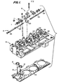
- FIG. 1 illustrates, in an exploded perspective view, the lubricant supply pipe or rail 2 and its location relative to the engine head 4 and a single rocker arm assembly 6.
- Intake valve 8 and exhaust valve 10 and their associated valve seats, referred to as 12 and 14, respectively, are shown adjacent the cylinder head gasket 16.
- the cylinder head 4 includes on the upper surface a plurality of rocker arm pedestal mounts 18 integrally formed in the head.
- Each pedestal mount 18 has a flat upper surface and includes a pair of threaded apertures 20.
- Each rocker arm pedestal mount also includes a nose portion 22 which functions as a support for the lubricant supply pipe 2 in a manner which will be explained in more detail hereinbelow.
- rocker arm pedestal mounts which are charaterized by a flat planar surface located parallel to the longitudinal axis of the engine for engaging the rocker arm pedestals allows these structures to be machined easily during formation of the engine cylinder head, thus reducing manufacturing costs associated with prior art rocker arm mounting structures.
- the nose portion 22 of an end rocker pedestal mount 24 includes an outlet port 26 for the portion of the engine lubrication circuit contained within the cylinder head (not shown).
- the lubricant supply pipe 2 is configured to be inserted through an extension 28 of the rocker arm support pedestal 30 so that when the support pedestal is secured to the rocker pedestal mount 18 as described in detail in the aforesaid copending European Patent Application No. 86 , the lubricant supply pipe is held in sealing fluid engagement therewith.
- Figures 2 and 3 illustrate the cross-sectional configurations of the lubricant supply pipe 2 in the longitudinal direction and perpendicular to the longitudinal, respectively.
- the lubricant supply pipe 2 includes a conduit portion 40 and end caps 42.
- the conduit portion 40 includes a bottom wall section 44 with a flat outer surface 46.
- An arcuate hood section 48 is integrally connected to the bottom wall section 44 to form top and side walls enclosing a lubricant passage 50.
- the cross-sectional configuration shown in Figure 3 and formed by the integral connection of the arcuate hood section 46 and flat bottom wall section 44 conforms to that of the extension 28 of the rocker arm support pedestal which is designed' to secure pipe 2 in fluid alignment with each rocker arm pedestal lubrication circuit.
- both the pedestal 30 and the supply pipe 2 together form a substantially smooth flat planar surface, engagement with the planar pedestal mount 18 on the cylinder head is facilitated. Moreover, the same flat surface on the head can form both the rocker arm pedestal mount and the lubricant supply pipe engaging and sealing surface, thereby further reducing engine head machining costs.
- the transverse distance between the top of the arcuate hood 48 and the bottom wall 46 for the conduit portion 40 of the supply pipe is selected so that it is greater than that of extension 28 by the distance between arrows 45 in Figure 3.
- This causes the conduit portion bottom wall to be compressed against the nose portion 22 of the cylinder head pedestal mount 24 when the rocker arm support assembly is biased against the head.
- the compression of the bottom wall around inlet port 52 automatically creates a fluid tight seal when the lubricant supply rail and rocker arm support assembly are secured to the head. An effective seal is thus formed without the need for forming the conduit portion to correspond exactly to the height of extension 28.
- conduit 40 facilitates both lubricant transfer to each rocker pedestal and the sealing engagement of the lubricant supply pipe 2 with all of the rocker pedestals.
- a lubricant inlet port 52 is positioned toward each end cap 42 in the conduit bottom wall section 44. The exact location of the inlet ports 52 is determined to cause automatic alignment between the cylinder head lubricant outlet port 26 and one of the ports 52 when the lubricant supply tube is engaged by the extensions 28 of the rocker arm support pedestal 30 associated with the pedestal mount 24 containing port 26. Since an inlet port 52 is located the same distance from each end of the pipe 2, a proper fluid connection is formed with port 52 regardless of which end of pipe 2 is mounted adjacent port 26. The inlet port 52 at the opposite end of the engine is merely sealed against the corresponding pedestal mount 18 by the associated pedestal.
- the arcuate hood portion 48 of the conduit is provided with a plurality of evenly spaced lubricant transfer bores 54 which are positioned to communicate with internal lubrication channels in the rocker arm support pedestal extension 28.
- One such channel 55 is shown in Figure 3.
- Lubricant is directed from lubricant passage 50 through transfer bore 54 and into channel 55 along the path shown by arrows 57.
- Channel 55 further provides fluid communication downstream of arrows 57 with lubricant flow passages (not shown) integrally formed in the interior of the rocker arm support pedestal 30.
- Lubricant is from there directed into the interior of the support pedestal, to the shaft and from there to the rocker arms and push rods in a manner which,is shown and described in detail in the aforesaid copending European Patent Application No.
- One transfer bore 54 is provided to correspond with each rocker arm assembly 6.
- the transfer bores 54 are further positioned to align with the pedestal extension lubrication channels 55 of each associated rocker arm assembly when the conduit 40 is inserted into the extensions from either end of the head during assembly and to provide direct fluid communication between the engine lubricant supply circuit and the interior lubrication circuit of each associated rocker arm assembly when the lubricant supply rail is operably installed on the engine cylinder head.
- the lubricant supply tube may be constructed of any suitable inert, durable material which will withstand the temperature and other operating conditions commonly encountered ih the engine environment.
- Nylon has been found to be a particularly suitable material.
- any similar material such as, for example, one of the many suitable plastics or even metal, could be used with substantially similar results.
- the end caps 42 are preferably formed from the same or a similar compatible material as the conduit 40.
- the preferred method of attachment for the end caps 42 is by ultrasonic welding. These techniques are well known to those skilled in the art.
- an end cap or sealing member 42 having the configuration shown in Figures 4a and 4b has been found to be effective.
- Other end cap configurations which serve the same function could be employed as well.
- each end cap includes an end wall portion 56 and a sealing protrusion 58.
- at least one welding projection 60 is provided.
- An annular groove 62 which is shown enlarged in Figure 4b, is provided at the junction between end wall portion 56 and sealing protrusion 58. This functions to seat the end of conduit 40 and aids in positioning end cap 42 correctly on the conduit end prior to welding.
- the exact configuration of the annular groove 62 will conform to the cross-sectional configuration of the conduit 40 shown in Figure 3.
- the configuration of sealing protrusion 58 shown in Figure 4a has been found to produce enhanced sealing following the ultrasonic welding of the end caps on the ends of conduit 40.
- the means used to seal the conduit ends must be able to withstand the pressures reached without leaking for sustained periods of time.
- Ultrasonic welding is the preferred method of sealing, particularly when the lubrication supply tube is made of nylon.
- the actual method employed will depend in large measure on the material chosen for the conduit and end caps.
- the present lubricant supply rail will find its primary application to supply lubricant from the lubrication circuit of an internal combustion engine to the bearing surfaces of the rocker arms, the valves and the push rods. It may be easily installed during engine assembly to provide automatic fluid communication between the cylinder head lubricant outlet port and the interior lubricant channels of the rocket arm support assembly. The precise location of equally spaced lubricant transfer bores in the conduit portion of the lubricant supply rail relative to the positions of two lubricant inlet ports allows the supply rail or pipe to be correctly installed with either end over the cylinder head lubricant outlet. If required, the lubricant supply rail of the present invention may also be replaced quickly and easily.
Landscapes
- Engineering & Computer Science (AREA)
- Mechanical Engineering (AREA)
- General Engineering & Computer Science (AREA)
- Lubrication Of Internal Combustion Engines (AREA)
- Lubrication Details And Ventilation Of Internal Combustion Engines (AREA)
Applications Claiming Priority (2)
| Application Number | Priority Date | Filing Date | Title |
|---|---|---|---|
| US06/749,754 US4628875A (en) | 1985-06-28 | 1985-06-28 | Lubricant supply rail |
| US749754 | 1996-10-24 |
Publications (2)
| Publication Number | Publication Date |
|---|---|
| EP0206809A1 true EP0206809A1 (fr) | 1986-12-30 |
| EP0206809B1 EP0206809B1 (fr) | 1990-03-21 |
Family
ID=25015045
Family Applications (1)
| Application Number | Title | Priority Date | Filing Date |
|---|---|---|---|
| EP86304868A Expired EP0206809B1 (fr) | 1985-06-28 | 1986-06-24 | Barre d'alimentation en lubrifiant |
Country Status (4)
| Country | Link |
|---|---|
| US (1) | US4628875A (fr) |
| EP (1) | EP0206809B1 (fr) |
| JP (1) | JPS623114A (fr) |
| DE (1) | DE3669748D1 (fr) |
Cited By (1)
| Publication number | Priority date | Publication date | Assignee | Title |
|---|---|---|---|---|
| EP1541815A3 (fr) * | 2003-12-09 | 2008-12-24 | Nissan Motor Company, Limited | Dispositif de commande variable de soupape pour moteur à combustion interne |
Families Citing this family (4)
| Publication number | Priority date | Publication date | Assignee | Title |
|---|---|---|---|---|
| US5213074A (en) * | 1990-12-26 | 1993-05-25 | Ryobi Limited | Lubricating device of four-stroke cycle engine unit for portable working machine |
| US5577470A (en) * | 1995-11-06 | 1996-11-26 | Ford Motor Company | Valve system for internal combustion engine |
| DE20314366U1 (de) | 2002-09-16 | 2004-05-19 | Perkins Engines Co. Ltd. | Zylinderkopf mit einem integral gegossenen Kipphebelwellenfussstück |
| US7395802B2 (en) * | 2006-06-07 | 2008-07-08 | Ford Global Technologies, Llc | Oil supply for internal combustion engine camshaft |
Citations (4)
| Publication number | Priority date | Publication date | Assignee | Title |
|---|---|---|---|---|
| US1455244A (en) * | 1921-12-19 | 1923-05-15 | Finnell Charlie | Lubricating system |
| GB223393A (en) * | 1923-10-08 | 1924-10-23 | Montague Ernest Simes Junior | Improvements in the mode of and means for lubricating internal combustion engine overhead valve mechanism |
| FR616959A (fr) * | 1926-06-01 | 1927-02-11 | Dispositif de graissage pour culbuteurs | |
| GB355400A (en) * | 1930-06-05 | 1931-08-27 | Lea & Francis Ltd | Lubrication of the valve-operating mechanism of internal-combustion engines |
Family Cites Families (10)
| Publication number | Priority date | Publication date | Assignee | Title |
|---|---|---|---|---|
| US1363500A (en) * | 1920-12-28 | Internal-combustion engine | ||
| US1393913A (en) * | 1917-04-06 | 1921-10-18 | Gen Motors Corp | Hydrocarbon-motor |
| US1438163A (en) * | 1921-08-23 | 1922-12-05 | Joseph H Montgomery | Forced-feed oiler |
| US1491710A (en) * | 1923-03-12 | 1924-04-22 | Archibald Dickson | Automatic valve-stem guide and rocker-arm wick lubricator |
| US1784767A (en) * | 1928-08-24 | 1930-12-09 | Gen Motors Corp | Hydraulic valve mechanism |
| US2104729A (en) * | 1928-12-29 | 1938-01-11 | Auto Research Corp | Automatic centralized lubricating installation |
| US2224376A (en) * | 1936-11-18 | 1940-12-10 | Gen Motors Corp | Valve mechanism temperature regulator |
| US3008544A (en) * | 1960-11-10 | 1961-11-14 | Krizman Mfg Co Inc | Lubricating system |
| JPS5837911B2 (ja) * | 1976-10-07 | 1983-08-19 | 日本電信電話株式会社 | 記録用ヘッド |
| JPS5837911U (ja) * | 1981-09-08 | 1983-03-11 | ヤンマーディーゼル株式会社 | 内燃機関の弁腕室 |
-
1985
- 1985-06-28 US US06/749,754 patent/US4628875A/en not_active Expired - Lifetime
-
1986
- 1986-06-24 EP EP86304868A patent/EP0206809B1/fr not_active Expired
- 1986-06-24 DE DE8686304868T patent/DE3669748D1/de not_active Expired - Lifetime
- 1986-06-27 JP JP61151304A patent/JPS623114A/ja active Granted
Patent Citations (4)
| Publication number | Priority date | Publication date | Assignee | Title |
|---|---|---|---|---|
| US1455244A (en) * | 1921-12-19 | 1923-05-15 | Finnell Charlie | Lubricating system |
| GB223393A (en) * | 1923-10-08 | 1924-10-23 | Montague Ernest Simes Junior | Improvements in the mode of and means for lubricating internal combustion engine overhead valve mechanism |
| FR616959A (fr) * | 1926-06-01 | 1927-02-11 | Dispositif de graissage pour culbuteurs | |
| GB355400A (en) * | 1930-06-05 | 1931-08-27 | Lea & Francis Ltd | Lubrication of the valve-operating mechanism of internal-combustion engines |
Cited By (1)
| Publication number | Priority date | Publication date | Assignee | Title |
|---|---|---|---|---|
| EP1541815A3 (fr) * | 2003-12-09 | 2008-12-24 | Nissan Motor Company, Limited | Dispositif de commande variable de soupape pour moteur à combustion interne |
Also Published As
| Publication number | Publication date |
|---|---|
| EP0206809B1 (fr) | 1990-03-21 |
| US4628875A (en) | 1986-12-16 |
| DE3669748D1 (de) | 1990-04-26 |
| JPH0320572B2 (fr) | 1991-03-19 |
| JPS623114A (ja) | 1987-01-09 |
Similar Documents
| Publication | Publication Date | Title |
|---|---|---|
| EP0211503B1 (fr) | Ensemble de support | |
| EP0509804B1 (fr) | Arrangement pour le montage et la connexion pour une pompe d'injection de carburant | |
| US5513604A (en) | Valve cover for high performance engines having integral oil passages | |
| EP0662581B1 (fr) | Conduite de liaison | |
| US4628875A (en) | Lubricant supply rail | |
| CN105569770A (zh) | Pcv阀的安装结构 | |
| US5551382A (en) | Cooling system for an internal combustion engine | |
| CN113550807A (zh) | 发动机 | |
| US4699100A (en) | Chamber construction for internal combustion engine | |
| US4593655A (en) | Valve seat ring cooling apparatus | |
| US5555856A (en) | Oil-cooled reciprocating internal combustion engine | |
| US6591807B1 (en) | Combination comprising a main unit and at least one add-on functional unit | |
| KR100382385B1 (ko) | 스크류형압축기 | |
| CN210564788U (zh) | 一种柴油机缸盖及柴油机 | |
| CN111120035B (zh) | 跨越式润滑油道结构及发动机 | |
| CN108006425A (zh) | 气动浸入式润滑剂泵及润滑剂泵送系统 | |
| CN1373832A (zh) | 发动机,特别是活塞式发动机 | |
| CN219865259U (zh) | 一种气缸盖总成、发动机及车辆 | |
| US10526998B2 (en) | Pressure controlled dynamic seal with captured fluid transfer tubes | |
| CN214616864U (zh) | 一种液压马达的通油盘 | |
| CN214092069U (zh) | 一种机油泵壳集成反馈油道与活塞冷却喷嘴封堵功能结构 | |
| KR100258745B1 (ko) | 유동구조를갖는실린더헤드의리어커버 | |
| JPH04244686A (ja) | 高温ガス制御用バルブ装置 | |
| JPH0717777Y2 (ja) | 油冷エンジンのオイルクーラ取付装置 | |
| JPS6345523Y2 (fr) |
Legal Events
| Date | Code | Title | Description |
|---|---|---|---|
| PUAI | Public reference made under article 153(3) epc to a published international application that has entered the european phase |
Free format text: ORIGINAL CODE: 0009012 |
|
| AK | Designated contracting states |
Kind code of ref document: A1 Designated state(s): DE GB |
|
| 17P | Request for examination filed |
Effective date: 19870604 |
|
| 17Q | First examination report despatched |
Effective date: 19880223 |
|
| GRAA | (expected) grant |
Free format text: ORIGINAL CODE: 0009210 |
|
| AK | Designated contracting states |
Kind code of ref document: B1 Designated state(s): DE GB |
|
| REF | Corresponds to: |
Ref document number: 3669748 Country of ref document: DE Date of ref document: 19900426 |
|
| PLBE | No opposition filed within time limit |
Free format text: ORIGINAL CODE: 0009261 |
|
| STAA | Information on the status of an ep patent application or granted ep patent |
Free format text: STATUS: NO OPPOSITION FILED WITHIN TIME LIMIT |
|
| 26N | No opposition filed | ||
| REG | Reference to a national code |
Ref country code: GB Ref legal event code: IF02 |
|
| PGFP | Annual fee paid to national office [announced via postgrant information from national office to epo] |
Ref country code: GB Payment date: 20030619 Year of fee payment: 18 |
|
| PGFP | Annual fee paid to national office [announced via postgrant information from national office to epo] |
Ref country code: DE Payment date: 20030630 Year of fee payment: 18 |
|
| PG25 | Lapsed in a contracting state [announced via postgrant information from national office to epo] |
Ref country code: GB Free format text: LAPSE BECAUSE OF NON-PAYMENT OF DUE FEES Effective date: 20040624 |
|
| PG25 | Lapsed in a contracting state [announced via postgrant information from national office to epo] |
Ref country code: DE Free format text: LAPSE BECAUSE OF NON-PAYMENT OF DUE FEES Effective date: 20050101 |
|
| GBPC | Gb: european patent ceased through non-payment of renewal fee |
Effective date: 20040624 |