EP0206708A2 - Automatic water feeding device - Google Patents
Automatic water feeding device Download PDFInfo
- Publication number
- EP0206708A2 EP0206708A2 EP86304608A EP86304608A EP0206708A2 EP 0206708 A2 EP0206708 A2 EP 0206708A2 EP 86304608 A EP86304608 A EP 86304608A EP 86304608 A EP86304608 A EP 86304608A EP 0206708 A2 EP0206708 A2 EP 0206708A2
- Authority
- EP
- European Patent Office
- Prior art keywords
- water
- water feeding
- storage tank
- head
- earth
- Prior art date
- Legal status (The legal status is an assumption and is not a legal conclusion. Google has not performed a legal analysis and makes no representation as to the accuracy of the status listed.)
- Withdrawn
Links
Images


Classifications
-
- A—HUMAN NECESSITIES
- A01—AGRICULTURE; FORESTRY; ANIMAL HUSBANDRY; HUNTING; TRAPPING; FISHING
- A01G—HORTICULTURE; CULTIVATION OF VEGETABLES, FLOWERS, RICE, FRUIT, VINES, HOPS OR SEAWEED; FORESTRY; WATERING
- A01G27/00—Self-acting watering devices, e.g. for flower-pots
- A01G27/008—Component parts, e.g. dispensing fittings, level indicators
-
- A—HUMAN NECESSITIES
- A01—AGRICULTURE; FORESTRY; ANIMAL HUSBANDRY; HUNTING; TRAPPING; FISHING
- A01G—HORTICULTURE; CULTIVATION OF VEGETABLES, FLOWERS, RICE, FRUIT, VINES, HOPS OR SEAWEED; FORESTRY; WATERING
- A01G27/00—Self-acting watering devices, e.g. for flower-pots
Definitions
- the method is practised with one or more water supply pipes extending above a line of growing plants in a cultivating field allowing a predetermined volume of water to drip onto the ground in the region in which the roots of the plants spread.
- This method has the advantage that no water will be fed to regions where watering is not required, the supply of water being concentrated into the required areas. This method therefore achieves a better use of the water supply from a source and, for a given quantity of water will achieve an increased rate of harvest of a crop.
- this water dripping method still involves a number of drawbacks. Specifically, it is difficult to properly adjust the rate of water drip from the supply pipes. There is again an unavoidable loss of water due to evaporation as the water is fed to the surface of the earth from above. In order to reach the roots, a volume of water greater than that which would be required simply for feeding the plants must be dripped onto the ground. In an effort further to improve on the foregoing proposal, it has been suggested to feed water by an underground system.
- a number of water supply tubes are connected one to another with water permeable tubes having a plurality of capillary pores formed thereon being interposed between adjacent water supply tubes, the end one of each run of water supply tubes being coupled to a water supply source and the water permeable pipes being embedded in the earth of the cultivating field.
- an automatic water feeding device of the type including a water storage tank, a water feeding head and a water supply tube extending therebetween, characterised in that said water feeding head comprises: a generally tubular water feeding portion made of water permeable material and having a closed end, said water feeding portion being adapted to be plunged into the earth or other growing medium in the region of the roots of a plant to be watered, and a head portion made of water-tight material coupled to the upper open end of the water feeding portion; and in that an outlet port through which water to be fed is delivered to the head portion via said water supply tube is provided at a position in the vicinity of the bottom of the water storage tank, whereby the surface level of water in the water storage tank may be below the surface level of the earth or other growing medium into which the water feeding portion is plunged.
- the automatic water feeding device Xa includes a water storage tank 1 serving as water supply source, a water supply.tube 50 made of elastomeric material such as rubber or the like having excellent flexibility and a water feeding head 60 through which water is fed to the earth or other growing medium in the region of the roots of a plant to be watered.
- the water storage tank 1 is so designed that any person can easily carry it by themself, and is suitably made of a plastics material.
- the water storage tank 1 comprises a bottom 10, an intermediate portion 20 including a circumextending wall, and a top 30 assembled into an integral construction with the use of adhesive, and has a generally rectangular cross-section.
- the intermediate portion 20 has a front side plate 21 which is formed with a recess 22 in the area extending down from the upper end of the front side plate 21 to a position adjacent the bottom 10.
- a generally horizontally extending portion 23 in the recess 22 is provided with one or more spigot tubes 24 therethrough.
- one said tube is coupled at 26 to the lower end of a water level meter 27.
- the lower end of water supply tube 50 is fitted on to the upper end of another spigot tube.
- Fig. 1 shows a cap fitted on to the upper end of one said spigot tube 24 not in operation, thereby to inhibit a leakage of water therefrom.
- a funnel-shaped water inlet port 31 and a short air vent tube 35 are integrally formed in the top 30.
- the water inlet port 31 has a water supply pipe 32 connected thereto and extending down to a position adjacent the bottom 10.
- Air vent tube 25 is fitted with a screw 37 which is threadably engaged to a threaded air vent hole 36 to function as a vave, a packing 38 being interposed between the screw 37 and the lower end of threaded hole 36 which has a reduced diameter.
- the tank also has an upper front edge member 40 provided with a short tube (not shown) on to which the upper open end of the water level meter 27 is fitted and a plurality of cut-outs 41 for holding the water supply tubes 50 at an intermediate section thereof.
- the water supply tube 50 is an ordinary tube made of elastomeric material having excellent flexibility and it may be transparent or may be opaque. However, for convenience we prefer the tube to be transparent.
- the water feeding head 60 comprises a generally tubular water feeding portion 61 made of porous ceramic material adapted to be plunged into a flowerpot in the region where the roots of a plant spread in the earth or other growing medium and a head portion 62 made of watertight plastics material which is tightly engaged to the upper open end of the water feeding portion 61.
- the bottom end of the water feeding portion 61 is closed with a generally conical end.
- the above-mentioned water feeding portion preferably comprises unglazed pottery produced by the steps of mixing clay as the main raw material with fine synthetic resin powder and burning out the thus prepared mixture at an elevated temperature in the range of 1,200 to 1,600°C which evaporates the components of the synthetic resin powder. After completion of such evaporation a large number of very fine invisible capillary pores are left behind over the whole surface area of the unglazed pottery. Water will ooze through the capillary pores under the effect of differential pressure across the wall of the unglazed pottery.
- the water feeding portion has inner and outer diameters, thickness and length which may be selected in dependence upon the size of flowerpot and the kind of plant to be watered.
- the water feeding portion 61 has a hollow interior and its upper proximal end is open to the outside while its lower end is closed with a tapered generally conical portion.
- the water feeding portion 61 is designed in an elongated generally tubular configuration which allows it easily to be plunged into earth or other growing media.
- valve screw 37 is first rotated to displace it from the packing 38 to vent air through the air vent hole 36.
- the water feeding head 60 is located at a position above the water storage tank 1 and water W is then introduced into the water storage tank 1 via the water inlet port 31 (Fig. 6(A)).
- the valve screw 67 on the water feeding head 60 is loosened to displace it from the packing 66 to open the air vent hole 65.
- the water feeding head 60 is lowered below the level of water in the water storage tank 1 whereby both the water supply tube 50 and the water feeding head 60 are filled with water W.
- both the valve screws 37 and 67 are rotated to close the respective air vent holes 36 and 65.
- the water storage tank 1 of the device X a is placed at a position below the flowerpot 70 as shown in Fig. 5 and the water feeding portion 61 of the water feeding head 60 is then plunged into the earth or other growing medium T in the flowerpot 7Q until the skirt 68 of the head portion 62 is embedded in the earth.T. Water held in the water storage tank 1 will then ooze into the earth or other growing medium through the water feeding portion 61 absorbtion depending on the degree of dryness of the earth or other growing medium whereby water feeding is automatically effected.
- the volume of water W in the water storage tank 1 decreases correspondingly.
- the initial space S a in the water storage tank 1 is increased to a space S b corresponding to the reduction of water W in the water storage tank 1 whereby pressure in the space S b becomes less than atmospheric, because the interior of the water storage tank 1 is closed.
- the water level in the water supply pipe 32 is caused to lower corresponding to differential pressure between the atmospheric pressure and pressure in the space S b until a water level L f is reached.
- the pressure appearing in the horizontally extending plane H including the lower end of the water supply pipe 32 is maintained at a substantially constant level (i.e atmospheric) at all times irrespective of how much the space S d (Fig. 6(D)) in the water storage tank 1 exceeds the space S c at which the water level L in the water supply pipe 32 first reaches the lower end of the latter as shown in Fig. 6(C).
- Fig. 7 illustrates by way of a perspective view another embodiment of automatic water feeding device X b .
- the device X b is formed integrally with its flowerpot, plant holder or the like, which has a relatively thick wall thickness so as to accommodate the water tank of device X b . Since the device X b is otherwise substantially similar to the device X a in structure and function, the components of the device X b are identified by reference numerals corresponding to those of the device X but increased by 100, and it is therefore thought that a repeated description will not be required.
- the barrel portion of the flowerpot 170 is identified 171 and will be seen to have a substantial wall thickness.
- Fig. 8 schematically illustrates another embodiment of automatic water feeding device intended for use in large-scale cultivation, for example in a farm or horticultural nursery.
- the device X usable for such a large-scale cultivation is substantially similar to the device X a with the exception of increased capacity, its components are identified by reference numerals corresponding to those of the device X , but increased by 200, and a repeated description should not be necessary.
- the main water supply tube 250 divides into branched tubes 251a and 251b and those in turn have a plurality of twig tubes 252a and 252b leading thereoff and each in communication with a respective water feeding head 260.
- reference numerals 272a and 272b designate a ridge in.the farm field respectively.
- the embodiments of automatic water feeding device described hereinabove include a number of very significant features. Firstly, it will be seen that a sufficient volume of water is automatically fed to the region of the roots of a plant without any necessity for a consideration of the rate of evaporation of water fed from above by conventional watering means and without any need for a mechanical pumping means. Since operation of the embodiments of automatic watering device depend on the absorbtive power of the earth or other growing medium, which in turn depends on the degree of dryness of the earth at any one time, the earth should not become saturated and the wetted region of the earth will gradually increase by diffusion of water through the earth as the supplied water continues to ooze thereinto.
- Embodiments of device in accordance with the present invention can readily be used either for large-scale cultivation or for micro-cultivation on a flowerpot scale.
Abstract
An automatic water feeding device includes a water storage tank, a water feeding head and a water supply tube extending therebetween. The water feeding head is constituted by the combination of a generally tubular water feeding portion made of water permeable material and having a closed end and a head portion made of watertight material coupled to the upper open end of the water feeding portion. The water feeding tubular portion is adapted to be plunged into the earth or other growing medium in the region of the roots of a plant to be watered. An outlet port through which water to be fed is delivered to the head portion via the water supply tube is provided at a position in the vicinity of the bottom of the water storage tank. The surface level of water in the water storage tank may be below the surface level of the earth or other growing medium into which the water feeding portion is plunged.
Description
- This invention relates to automatic water feeding devices.
- Many arrangements for watering agricultural crops in the field or houseplants and the like in greenhouses have been previously proposed. None is entirely satisfactory.
- For example, the spreading of water over agricultural crops from above by the use of a plurality of sprinklers in spaced locations has been widely used. This method involves a relatively large volume of water in order to maintain the roots of the plants in an adequately wet state. Much water is lost by evaporation. Watering in this fashion when the plants are in bloom may adversely affect a fruit crop.
- In an effort to overcome these problems, it has more recently been proposed to allow water to drip onto the earth to wet the ground with a relatively smaller volume of water only where the roots of individual plants spread. In that this achieves a more effective utilization of precious water supplies, it has attracted much attention.
- In specific arrangements, the method is practised with one or more water supply pipes extending above a line of growing plants in a cultivating field allowing a predetermined volume of water to drip onto the ground in the region in which the roots of the plants spread...This method has the advantage that no water will be fed to regions where watering is not required, the supply of water being concentrated into the required areas. This method therefore achieves a better use of the water supply from a source and, for a given quantity of water will achieve an increased rate of harvest of a crop.
- However, this water dripping method still involves a number of drawbacks. Specifically, it is difficult to properly adjust the rate of water drip from the supply pipes. There is again an unavoidable loss of water due to evaporation as the water is fed to the surface of the earth from above. In order to reach the roots, a volume of water greater than that which would be required simply for feeding the plants must be dripped onto the ground. In an effort further to improve on the foregoing proposal, it has been suggested to feed water by an underground system. Under this proposal, a number of water supply tubes are connected one to another with water permeable tubes having a plurality of capillary pores formed thereon being interposed between adjacent water supply tubes, the end one of each run of water supply tubes being coupled to a water supply source and the water permeable pipes being embedded in the earth of the cultivating field.
- This method represents a substantial improvement in the utility of the water supply in that effective wetting of the roots with a small volume of water is readily achieved with an overall reduced consumption of supplied water and a relatively increased rate of harvest for a given water supply. However, there are again drawbacks. The arrangement of water supply tubes and water permeable tubes has to be selected in dependence on the nature of the plants concerned and like factors. There is a necessity for the water supply tubes to be embedded in the earth and moreover a necessity for removing them from the earth before or after a period of harvesting. Clearly this will result in many man-hours being required to carry out these operations. Thus, even this improved method involves a lower economical efficiency.
- A further drawback inherent in each of the above described prior proposed automatic water feeding systems is that they are all intended for large scale plant cultivation. None of these means is adapted for use on a small scale, for example down to single flowerpot scale. Additionally, each of these prior watering systems requires some form of pumping means or the like.
- The present invention has arisen from our work in seeking to overcome the various drawbacks inherent in the prior proposals described above. As will become clear from the description which follows, automatic water feeding-systems in accordance with the present invention can be produced for use in a large-scale farm system and also for small-size cultivation right down to flowerpot scale.
- It will also become clear from the detailed description which follows that the described embodiments of automatic water feeding device in accordance with the present invention do not include any form of mechanical driving means. In the described arrangements, water is utilized by being absorbed into the earth or other growing medium as that medium dries.
- In accordance with the present invention, we provide an automatic water feeding device of the type including a water storage tank, a water feeding head and a water supply tube extending therebetween, characterised in that said water feeding head comprises: a generally tubular water feeding portion made of water permeable material and having a closed end, said water feeding portion being adapted to be plunged into the earth or other growing medium in the region of the roots of a plant to be watered, and a head portion made of water-tight material coupled to the upper open end of the water feeding portion; and in that an outlet port through which water to be fed is delivered to the head portion via said water supply tube is provided at a position in the vicinity of the bottom of the water storage tank, whereby the surface level of water in the water storage tank may be below the surface level of the earth or other growing medium into which the water feeding portion is plunged.
- The invention is hereinafter more particularly described by way of example only, with reference to the accompanying drawings, in which:-
- Fig. 1 is an overall perspective view of a first embodiment of automatic water feeding device constructed in accordance with the present invention;
- Fig. 2 is a vertical sectional view taken generally along the Line II-II in Fig. 1 and with the water feeding portion of the water feeding head plunged into the earth or other growing medium;
- Fig. 3 is an enlarged perspective view of the water feeding head;
- Fig. 4 is an enlarged vertical sectional view of the water feeding head of Fig. 3, but shown plunged into the earth or other growing medium;
- Fig. 5 is a somewhat schematic side view of the device in use with a flowerpot;
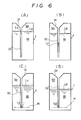
- Figs. 6(A) to (D) are a schematic vertical sectional view of a water storage tank of the device for explaining how water feeding is automatically effected;
- Fig. 7 is a perspective view of a second embodiment of automatic water feeding device in accordance with this invention, wherein the device is made integral with a flowerpot; and
- Fig. 8 is a schematic view of another embodiment of automatic water feeding device in accordance with this invention, wherein the device is intended for use in large-scale cultivation.
- Referring to Figs. 1 and 2 of the drawings, it will be seen that the automatic water feeding device Xa includes a
water storage tank 1 serving as water supply source, awater supply.tube 50 made of elastomeric material such as rubber or the like having excellent flexibility and awater feeding head 60 through which water is fed to the earth or other growing medium in the region of the roots of a plant to be watered. - As this particular embodiment is designed for use with a single flowerpot, the
water storage tank 1 is so designed that any person can easily carry it by themself, and is suitably made of a plastics material. As will be readily apparent from the drawings, thewater storage tank 1 comprises abottom 10, anintermediate portion 20 including a circumextending wall, and atop 30 assembled into an integral construction with the use of adhesive, and has a generally rectangular cross-section. - The
intermediate portion 20 has afront side plate 21 which is formed with arecess 22 in the area extending down from the upper end of thefront side plate 21 to a position adjacent thebottom 10. A generally horizontally extendingportion 23 in therecess 22 is provided with one ormore spigot tubes 24 therethrough. As shown, one said tube is coupled at 26 to the lower end of awater level meter 27. The lower end ofwater supply tube 50 is fitted on to the upper end of another spigot tube. Fig. 1 shows a cap fitted on to the upper end of one saidspigot tube 24 not in operation, thereby to inhibit a leakage of water therefrom. - A funnel-shaped
water inlet port 31 and a shortair vent tube 35 are integrally formed in thetop 30. Thewater inlet port 31 has awater supply pipe 32 connected thereto and extending down to a position adjacent thebottom 10. Air vent tube 25 is fitted with ascrew 37 which is threadably engaged to a threadedair vent hole 36 to function as a vave, apacking 38 being interposed between thescrew 37 and the lower end of threadedhole 36 which has a reduced diameter. - The tank also has an upper
front edge member 40 provided with a short tube (not shown) on to which the upper open end of thewater level meter 27 is fitted and a plurality of cut-outs 41 for holding thewater supply tubes 50 at an intermediate section thereof. - The
water supply tube 50 is an ordinary tube made of elastomeric material having excellent flexibility and it may be transparent or may be opaque. However, for convenience we prefer the tube to be transparent. - As will be best seen in Figs. 3 and 4, the
water feeding head 60 comprises a generally tubularwater feeding portion 61 made of porous ceramic material adapted to be plunged into a flowerpot in the region where the roots of a plant spread in the earth or other growing medium and ahead portion 62 made of watertight plastics material which is tightly engaged to the upper open end of thewater feeding portion 61. As is apparent from the drawings, the bottom end of thewater feeding portion 61 is closed with a generally conical end. - The above-mentioned water feeding portion preferably comprises unglazed pottery produced by the steps of mixing clay as the main raw material with fine synthetic resin powder and burning out the thus prepared mixture at an elevated temperature in the range of 1,200 to 1,600°C which evaporates the components of the synthetic resin powder. After completion of such evaporation a large number of very fine invisible capillary pores are left behind over the whole surface area of the unglazed pottery. Water will ooze through the capillary pores under the effect of differential pressure across the wall of the unglazed pottery. The water feeding portion has inner and outer diameters, thickness and length which may be selected in dependence upon the size of flowerpot and the kind of plant to be watered.
- The
water feeding portion 61 has a hollow interior and its upper proximal end is open to the outside while its lower end is closed with a tapered generally conical portion. Thus, thewater feeding portion 61 is designed in an elongated generally tubular configuration which allows it easily to be plunged into earth or other growing media. - The
head portion 62 includes awater introduction passage 64 extending from a sideways extendingstub pipe 63, on to which thewater supply tube 50 is fitted to the interior of the water feeding portion`6l. Anair vent hole 65 enables air to be vented from the interior of thewater feeding portion 61, theair vent hole 65 having aventing screw valve 67 threadably fitted thereto with anairtight packing 66 airtightly disposed below the bottom of thescrew 67. Thehead portion 62 further comprises askirt 68 which extends about the proximal end of the water feeding portion and has a plurality of generally gear tooth-shaped projections 69 formed on its exterior. Theprojections 69 on theflange 68 are intended to inhibit turning movement of thewater feeding head 60. - In operation of the above described embodiment, the
valve screw 37 is first rotated to displace it from the packing 38 to vent air through theair vent hole 36. At this time thewater feeding head 60 is located at a position above thewater storage tank 1 and water W is then introduced into thewater storage tank 1 via the water inlet port 31 (Fig. 6(A)). When the required volume of water W is filled in thewater storage tank 1, thevalve screw 67 on thewater feeding head 60 is loosened to displace it from the packing 66 to open theair vent hole 65. Then, thewater feeding head 60 is lowered below the level of water in thewater storage tank 1 whereby both thewater supply tube 50 and thewater feeding head 60 are filled with water W. When it is confirmed that they are filled with water W, both the valve screws 37 and 67 are rotated to close the respective air vent holes 36 and 65. - After completion of the above-mentioned operations the
water storage tank 1 of the device X a is placed at a position below theflowerpot 70 as shown in Fig. 5 and thewater feeding portion 61 of thewater feeding head 60 is then plunged into the earth or other growing medium T in the flowerpot 7Q until theskirt 68 of thehead portion 62 is embedded in the earth.T. Water held in thewater storage tank 1 will then ooze into the earth or other growing medium through thewater feeding portion 61 absorbtion depending on the degree of dryness of the earth or other growing medium whereby water feeding is automatically effected. - When the
tubular portion 61 of thewater feeding head 60 is first plunged into the earth T in the manner illustrated in Fig. 5, the water level L a of water W in thewater storage tank 1 is flush with the water level Le of water W in thewater supply pipe 32 as shown in Fig. 6(A). - As water W oozes into the earth under the effect of suction in dependence on the degree of dryness of the earth, the volume of water W in the
water storage tank 1 decreases correspondingly. As a result, the initial space Sa in thewater storage tank 1 is increased to a space Sb corresponding to the reduction of water W in thewater storage tank 1 whereby pressure in the space Sb becomes less than atmospheric, because the interior of thewater storage tank 1 is closed. Thus, as shown in Fig. 6(B), the water level in thewater supply pipe 32 is caused to lower corresponding to differential pressure between the atmospheric pressure and pressure in the space Sb until a water level Lf is reached. - Because the water level in the
water supply pipe 32 cannot fall below the lower end of the latter, the pressure appearing in the horizontally extending plane H including the lower end of thewater supply pipe 32 is maintained at a substantially constant level (i.e atmospheric) at all times irrespective of how much the space Sd (Fig. 6(D)) in thewater storage tank 1 exceeds the space Sc at which the water level L in thewater supply pipe 32 first reaches the lower end of the latter as shown in Fig. 6(C). - Thus, after the operative state shown in Fig. 6(C) is reached, feeding of water W into the earth T through the
tubular portion 61 is effected only when the earth T becomes dried and thus generates absorbtion greater than the pressure appearing in the plane H in the water storage tank 1)ignoring any small difference in height between the plane H and the lower open end of the spigot tube 24). - Next. Fig. 7 illustrates by way of a perspective view another embodiment of automatic water feeding device Xb. The device Xb is formed integrally with its flowerpot, plant holder or the like, which has a relatively thick wall thickness so as to accommodate the water tank of device Xb. Since the device Xb is otherwise substantially similar to the device X a in structure and function, the components of the device Xb are identified by reference numerals corresponding to those of the device X but increased by 100, and it is therefore thought that a repeated description will not be required. The barrel portion of the
flowerpot 170 is identified 171 and will be seen to have a substantial wall thickness. - Fig. 8 schematically illustrates another embodiment of automatic water feeding device intended for use in large-scale cultivation, for example in a farm or horticultural nursery. Since the device X usable for such a large-scale cultivation is substantially similar to the device Xa with the exception of increased capacity, its components are identified by reference numerals corresponding to those of the device X , but increased by 200, and a repeated description should not be necessary. It will be seen that the main
water supply tube 250 divides into branchedtubes twig tubes water feeding head 260. Furthermore,reference numerals - As will be clear from the preceding description, the embodiments of automatic water feeding device described hereinabove include a number of very significant features. Firstly, it will be seen that a sufficient volume of water is automatically fed to the region of the roots of a plant without any necessity for a consideration of the rate of evaporation of water fed from above by conventional watering means and without any need for a mechanical pumping means. Since operation of the embodiments of automatic watering device depend on the absorbtive power of the earth or other growing medium, which in turn depends on the degree of dryness of the earth at any one time, the earth should not become saturated and the wetted region of the earth will gradually increase by diffusion of water through the earth as the supplied water continues to ooze thereinto. Plants in bloom will not be adversely affected by sprinkled water and a relatively increased rate of harvest can be expected. There are no laborious operations involving the digging of the earth to lay water feeding sections by embedding them or for removing such sections on harvesting. Embodiments of device in accordance with the present invention can readily be used either for large-scale cultivation or for micro-cultivation on a flowerpot scale.
Claims (8)
1. An automatic water feeding device of the type including a water storage tank, a water feeding head and a water supply tube extending therebetween, characterised in that said water feeding head comprises: a generally tubular water feeding portion made of water permeable material and having a closed end, said water feeding portion being adapted to be plunged into the earth or other growing medium in the region of the roots of a plant to be watered, and a head portion made of water-tight material coupled to the upper open end of the water feeding portion; and in that an outlet port through which water to be fed is delivered to the head portion via said water supply tube is provided at a position in the vicinity of the bottom of the water storage tank, whereby the surface level of water in the water storage tank may be below the surface level of the earth or other growing medium into which the water feeding portion is plunged.
2. An automatic water feeding device as defined in Claim 1, further characterised in that said water feeding portion is made of a ceramic material having a multiplicity of very fine pores distributed over the whole surface area thereof and through which water to be fed is caused to ooze under the effect of a differential pressure across the wall of the water feeding portion.
3. An automatic water feeding device as defined in Claim 2, further characterised in that said water feeding portion is constructed in the form of unglazed pottery produced by the steps of mixing clay as the.main raw material with fine synthetic resin powder and then burning out the thus prepared mixture an an elevated temperature in the range of 1,200 to 1,600°C.
4. An automatic water feeding device as defined in any preceding claim, further characterised in that said head portion is provided with a water introduction hole through which water delivered from the water storage tank via the water supply tube is arranged to be operatively introduced into the interior of the water feeding portion and with an air vent hole through which air in the water feeding portion is arranged to be vented, said air vent hole being fitted with a valve.
5. An automatic water feeding device as defined in any preceding claim, further characterised in that said head portion has a skirt which extends about the proximal end of said water feeding portion, said skirt being adapted to be plunged into the earth or other growing medium together with the water feeding portion and having a plurality of projections formed thereon which are adapted to serve to inhibit turning movement of the water feeding head when it has been plunged into the earth or other growing medium.
6. An automatic water feeding device as defined in any preceding claim, further characterised in that the water supply tube comprises a main tube, a plurality of branch tubes which are branched from said main tube and a number of twig tubes, and in that each of said twig tubes communicates with a respective water feeding head.
7. An automatic water feeding device as defined in any preceding claim, further characterised in that the water storage tank comprises a bottom, a top and an intermediate portion including a circumextending wall; said intermediate portion being provided with one or more spigot tubes extending therethrough and having one open end located in the vicinity of the said bottom, the other open end thereof serving as said outlet port and being adapted to receive one end of the water supply tube; and said top being formed with a funnel-shaped water inlet port and an air vent hole which is fitted with a valve, said water inlet port having a water supply pipe connected thereto and extending down to a position adjacent the bottom.
8. An automatic water feeding device as- defined in any of Claims 1 to 6, further characterised in that the water storage tank is constituted by a hollow region in the wall of a flowerpot, plant holder or the like having a relatively thick wall, and in that the surface at the top of the wall of the flowerpot or the like is provided with a water inlet port to which a water supply pipe is connected internally of said water storage tank, the lower end of said water supply pipe being located at a position adjacent the bottom of said hollow region, with an air vent hole fitted with a valve, and with a spigot tube adapted to receive one end of the water supply tube, the other end of the spigot tube being located at a position adjacent the bottom of the hollow region.
Applications Claiming Priority (4)
| Application Number | Priority Date | Filing Date | Title |
|---|---|---|---|
| JP90636/85 | 1985-06-14 | ||
| JP9063585U JPS6221850U (en) | 1985-06-14 | 1985-06-14 | |
| JP9063685U JPS61207153U (en) | 1985-06-14 | 1985-06-14 | |
| JP90635/85 | 1985-06-14 |
Publications (2)
| Publication Number | Publication Date |
|---|---|
| EP0206708A2 true EP0206708A2 (en) | 1986-12-30 |
| EP0206708A3 EP0206708A3 (en) | 1987-06-16 |
Family
ID=26432094
Family Applications (1)
| Application Number | Title | Priority Date | Filing Date |
|---|---|---|---|
| EP86304608A Withdrawn EP0206708A3 (en) | 1985-06-14 | 1986-06-16 | Automatic water feeding device |
Country Status (2)
| Country | Link |
|---|---|
| EP (1) | EP0206708A3 (en) |
| KR (1) | KR870000006A (en) |
Cited By (5)
| Publication number | Priority date | Publication date | Assignee | Title |
|---|---|---|---|---|
| GB2240453A (en) * | 1990-02-02 | 1991-08-07 | William George Lyne | Self watering device for plants |
| EP0832556A2 (en) * | 1996-09-27 | 1998-04-01 | Adedamola Adebayo Andu | Automatic plant watering apparatus |
| AT501883B1 (en) * | 2005-09-12 | 2006-12-15 | Weninger Ges M B H | SELF-ACTIVE DEVICE FOR IRRIGATION OF CULTURAL PLANTS |
| US20160227718A1 (en) * | 2015-02-11 | 2016-08-11 | William Dunbar | Fluid Emitter concepts for feeding the root system of a plant |
| CN110291968A (en) * | 2018-03-22 | 2019-10-01 | 榆林市榆阳区林业工作站 | One kind being used for afforestation in sandy land jack watering device |
Citations (6)
| Publication number | Priority date | Publication date | Assignee | Title |
|---|---|---|---|---|
| FR1566566A (en) * | 1968-03-20 | 1969-05-09 | ||
| DE1582761B1 (en) * | 1965-06-29 | 1970-05-21 | Ipaco Internat Patent & Constr | Automatic device for irrigation of cultivated plants |
| DE2528748A1 (en) * | 1975-06-27 | 1976-12-30 | Manfred Dr Kitz | Continuous water supply for potted plant - has double bottomed inner pot with supply capillary and moist roll floated in outer tank |
| DE2655656A1 (en) * | 1975-12-12 | 1977-06-16 | Peter Weninger | Porous water reservoir which keeps flower pot moist - has means of regulating supply with tube leading to water reservoir |
| DE2416802B2 (en) * | 1974-04-06 | 1978-05-24 | Manfred Dr. 6314 Ulrichstein Kitz | Irrigation system for vascular plants |
| WO1981003411A1 (en) * | 1980-05-27 | 1981-12-10 | P Weninger | Method and device for the control of water supply to plants |
-
1986
- 1986-06-14 KR KR1019860004725A patent/KR870000006A/en not_active Application Discontinuation
- 1986-06-16 EP EP86304608A patent/EP0206708A3/en not_active Withdrawn
Patent Citations (6)
| Publication number | Priority date | Publication date | Assignee | Title |
|---|---|---|---|---|
| DE1582761B1 (en) * | 1965-06-29 | 1970-05-21 | Ipaco Internat Patent & Constr | Automatic device for irrigation of cultivated plants |
| FR1566566A (en) * | 1968-03-20 | 1969-05-09 | ||
| DE2416802B2 (en) * | 1974-04-06 | 1978-05-24 | Manfred Dr. 6314 Ulrichstein Kitz | Irrigation system for vascular plants |
| DE2528748A1 (en) * | 1975-06-27 | 1976-12-30 | Manfred Dr Kitz | Continuous water supply for potted plant - has double bottomed inner pot with supply capillary and moist roll floated in outer tank |
| DE2655656A1 (en) * | 1975-12-12 | 1977-06-16 | Peter Weninger | Porous water reservoir which keeps flower pot moist - has means of regulating supply with tube leading to water reservoir |
| WO1981003411A1 (en) * | 1980-05-27 | 1981-12-10 | P Weninger | Method and device for the control of water supply to plants |
Cited By (6)
| Publication number | Priority date | Publication date | Assignee | Title |
|---|---|---|---|---|
| GB2240453A (en) * | 1990-02-02 | 1991-08-07 | William George Lyne | Self watering device for plants |
| EP0832556A2 (en) * | 1996-09-27 | 1998-04-01 | Adedamola Adebayo Andu | Automatic plant watering apparatus |
| EP0832556A3 (en) * | 1996-09-27 | 1999-08-11 | Adedamola Adebayo Andu | Automatic plant watering apparatus |
| AT501883B1 (en) * | 2005-09-12 | 2006-12-15 | Weninger Ges M B H | SELF-ACTIVE DEVICE FOR IRRIGATION OF CULTURAL PLANTS |
| US20160227718A1 (en) * | 2015-02-11 | 2016-08-11 | William Dunbar | Fluid Emitter concepts for feeding the root system of a plant |
| CN110291968A (en) * | 2018-03-22 | 2019-10-01 | 榆林市榆阳区林业工作站 | One kind being used for afforestation in sandy land jack watering device |
Also Published As
| Publication number | Publication date |
|---|---|
| EP0206708A3 (en) | 1987-06-16 |
| KR870000006A (en) | 1987-02-16 |
Similar Documents
| Publication | Publication Date | Title |
|---|---|---|
| US4651468A (en) | Method and apparatus for natural fertilization and irrigation of plants | |
| CA2607906C (en) | Irrigation system and associated methods | |
| US7798746B2 (en) | Modular, self contained, engineered irrigation landscape and flower bed panel | |
| CN107182620B (en) | Drip irrigation type agricultural greenhouse system and greenhouse planting method | |
| EP1699285B1 (en) | Root and water management system for potted plants | |
| US20100219265A1 (en) | Water irrigation system including drip irrigation emitters | |
| US5836106A (en) | Plant watering control device | |
| EP0136476A2 (en) | Method and apparatus for natural fertilization and irrigation of plants | |
| US4928427A (en) | Irrigation system | |
| EP0206708A2 (en) | Automatic water feeding device | |
| JP2013135700A (en) | Subirrigation system | |
| CN203860115U (en) | Plant container | |
| CN113924956A (en) | Water-saving automatic infiltrating irrigation device | |
| AU2011224135B2 (en) | Irrigation system and associated methods | |
| JPH08107720A (en) | Plant cultivating device and method therefor | |
| JP3198640U (en) | Labor-saving bottom irrigation multi-variety container cultivation system | |
| CN217657235U (en) | Spring water conservation flower case of moisturizing for horticulture is planted | |
| JP2860320B2 (en) | Automatic watering device | |
| RU2219760C1 (en) | Drop irrigation system | |
| Ornstein | The Irristat TM: A moisture-sensitive self-regulating water valve for drip irrigation systems | |
| CN1224311C (en) | Water supply and water retention bag used for grewing plant and its application method | |
| JPH10113081A (en) | Plant cultivation device and plant shelf | |
| JP3100071U (en) | Automatic water supply | |
| CN105075700A (en) | Plant container | |
| AU2004298289B2 (en) | Root and water management system for potted plants |
Legal Events
| Date | Code | Title | Description |
|---|---|---|---|
| PUAI | Public reference made under article 153(3) epc to a published international application that has entered the european phase |
Free format text: ORIGINAL CODE: 0009012 |
|
| AK | Designated contracting states |
Kind code of ref document: A2 Designated state(s): DE FR GB IT NL |
|
| PUAL | Search report despatched |
Free format text: ORIGINAL CODE: 0009013 |
|
| AK | Designated contracting states |
Kind code of ref document: A3 Designated state(s): DE FR GB IT NL |
|
| STAA | Information on the status of an ep patent application or granted ep patent |
Free format text: STATUS: THE APPLICATION IS DEEMED TO BE WITHDRAWN |
|
| 18D | Application deemed to be withdrawn |
Effective date: 19871217 |
|
| RIN1 | Information on inventor provided before grant (corrected) |
Inventor name: TANIGAWA, HAJIME |