EP0206598A2 - Lampe à arc à halogénure métallique - Google Patents
Lampe à arc à halogénure métallique Download PDFInfo
- Publication number
- EP0206598A2 EP0206598A2 EP86304329A EP86304329A EP0206598A2 EP 0206598 A2 EP0206598 A2 EP 0206598A2 EP 86304329 A EP86304329 A EP 86304329A EP 86304329 A EP86304329 A EP 86304329A EP 0206598 A2 EP0206598 A2 EP 0206598A2
- Authority
- EP
- European Patent Office
- Prior art keywords
- electrode
- metal halide
- squeezed
- arc tube
- arc lamp
- Prior art date
- Legal status (The legal status is an assumption and is not a legal conclusion. Google has not performed a legal analysis and makes no representation as to the accuracy of the status listed.)
- Granted
Links
Images

Classifications
-
- H—ELECTRICITY
- H01—ELECTRIC ELEMENTS
- H01J—ELECTRIC DISCHARGE TUBES OR DISCHARGE LAMPS
- H01J61/00—Gas-discharge or vapour-discharge lamps
- H01J61/02—Details
- H01J61/36—Seals between parts of vessels; Seals for leading-in conductors; Leading-in conductors
- H01J61/366—Seals for leading-in conductors
-
- H—ELECTRICITY
- H01—ELECTRIC ELEMENTS
- H01J—ELECTRIC DISCHARGE TUBES OR DISCHARGE LAMPS
- H01J61/00—Gas-discharge or vapour-discharge lamps
- H01J61/82—Lamps with high-pressure unconstricted discharge having a cold pressure > 400 Torr
- H01J61/827—Metal halide arc lamps
Definitions
- the present invention relates to, in general, a high pressure metal vapor arc lamp.
- the invention relates to a metal halide arc lamp containing a fill including mercury and metal halide materials such as NaI, ScI 3 , etc..
- metal halide arc lamps have a quartz arc tube enclosing a pair of electrode shafts therein.
- the electrode shafts face each other, one shaft in each side, inside the tube, connecting with an individual external lead through a metalfoil.
- the metalfoil is made of high-melt point metals such as molybdenum.
- Each end of tube is squeezed to form a flat surface.
- the arc tube is filled with a starting rare gas such as argon, mercury, and a metal halide material such as NaI, ScI 3 .
- the squeezed parts are formed by using the following procedure.
- the main electrodes face each other along the elongated axis of the arc tube, one in each end of the arc tube. Each end is softened by heating and opposite sides are squeezed with a pair of pinchers.
- a gap is created around the electrode shaft because the diameter of electrode shaft is large.
- the gap is created lengthwise along the electrode shaft.
- the width of gap extends to the breadth direction of the squeezed part, or in the direction perpendicular to the elongated axis of the arc tube. This gap is required to absorb a difference in the thermal expansion coefficient between the metal of electrode and the squeezed glass.
- the metal halide enclosed in the arc tube enters into the gap.
- the temperature of the electrode shaft rises and the halide evaporates quickly.
- Evaporated halide provides high internal pressures in the narrow gap.
- a shelly crack is created in the squeezed part.
- this crack caused filler in the arc tube to leak, or the arc tube to be damaged.
- the thermal expansion coefficient of the electrode shaft is different from that of the squeezed part of tube, when an arc lamp was turned on and off, a crack was created in the glass of the squeezed part.
- the present invention seeks to provide a metal halide arc lamp with a long iife.
- the present invention provides a metal halide arc lamp comprising a quartz arc tube having individual squeezed portions at both ends thereof. Each squeezed portion defines an elongated space,extending along an electrode arranged therein, the minimum value (Lmin) of the width, in the direction perpendicular to the electrode, of which satisfies:
- FIGURE 1 shows a vertical section of an arc tube of a metal halide arc lamp with a 100 W rating.
- An arc tube 1 has a quartz envelope containing a fill of a proper amount of starting rare gas, such as argon, mercury and metal halide materials, e.g. NaI and ScI 3 .
- NaI and ScI 3 are able to improve characteristics of visible spectrum emitted from mercury. Na and Sc, however, quickly react on quartz. To prevent these metals from being reacted, Na and Sc are individually combined with iodine to be halogenated before they are enclosed in arc tube 1.
- rare earth metals such as Dy (Dysprosium) and Tm (Thulium) can be used as a filler. These materials are individually used, or used together with one another. In this case, the rare earth metals are halogenated and filled in the arc tube as described above.
- An auxiliary electrode 7 is arranged close to main electrode 3.
- Main electrodes 3 and 5, and auxiliary electrode 7 are connected to external leads 15, 17 and 19 through metal foils 9, 10 and 13 respectively.
- Metal foils 9, 10 and 13 are made of a metal with a high melt point such as molybdenum.
- arc tube 1 Both ends of arc tube 1 are heated and compressed to form squeezed parts 21 and 23 respectively. As the result, arc tube 1 has a hollow luminous area 25 between squeezed parts 21 and 23.
- Main electrodes 3 and 5 have electrode shafts 27 and 29, respectively, connected to metal foils 9 and 11 respectively. Main electrodes 3 and 5 are arranged opposite to one another in luminous area 25. Electrode shafts 27 and 29 are arranged in squeezed parts 21 and 23 respectively. When squeezed part 21 is formed, a gap 31 is created between electrode shaft 27 and glass material 21a of squeezed part 21. Gap 31 extends along electrode shaft 27, and expands breadthwise to electrode shaft 27. In the same way, a gap 33 is created between electrode shaft 29 and glass material 23a of squeezed part 23, and a gap 35 between a base portion 7a of auxiliary electrode 7 and glass material 21a of squeezed part 21.
- FIGURE 2 shows the section crossing along line A-A' in FIGURE 1, which illustrates squeezed part 23 of arc tube 1.
- the width (L) of gap 33 extends breadthwise to squeezed part 23 or to the direction perpendicular to the compressed direction of squeezed part 23.
- the width (L) of gap 33 defined by electrode shaft 29 and glass material 23a of squeezed part 23 is formed such that it becomes gradually wider from the middle portion of the gap towards
- the diameter of electrode shaft 29 is set to 0.4 mm, and the minimum value (Lmin) of the width of gap 33 in the squeezed part 23 is set to 0.2 mm.
- Lmin minimum value of the width of gap 33 in the squeezed part 23.
- gap 33 which has a sufficient width absorbes a difference in thermal expansion coefficient between electrode shaft 29 and squeezed glass 23a. This provides advantage that occurrence of cracks in the glass of squeezed part 23 caused by temperature changes occurring when the lamp is turned on and off is prevented.
- the width (L) of gaps 31, 33, and 35 can be limited to a specified value by changing the shape of pincher or the rate of application of pressure used for manufacturing a lamp.
- the following table shows the comparison between the minimum values (Lmin) of width (L) of gap 33 produced between electrode shaft 29 located in the lower position and squeezed glass 23a and a number of lamps cracking. Lamps of the same type as that in the embodiment described above are used as the sample. A total amount of the sample is 20.
- the lower limit is 11 atmospheres when the minimum value (Lmin) is 0.4 mm.
- the internal pressure of arc tube 1 is about 10 atmospheres when a 100 w rating metal halide arc lamp is activated, and there is some fluctuation of this internal pressure during manufacturing.
- the minimum value (Lmin) is set to less than 0.3 mm rather than 0.04 mm. This indicates that it is desirable that the minimum value (Lmin) is from 0.1 mm to 0.3 mm to meet both the crack and the initial pressure resistance characteristics.
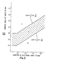
- FIGURE 3 shows the results of the tests carried out on lamps with various different main electrode diameters D and lamp inputs characteristics, in a similar way to the tests described above.
- the hatched region A in FIGURE 3 is the region where the probability of crack occurence is low during the life of the arc lamp, and where a squeezed part of an arc tube with initial pressure resistance enough for practical use can be obtained.
- the region B represents the area where the probability of crack occuring during the service life is high.
- the region C represents the area where the initial pressure resistance is low.
- FIGURE 3 shows the following correlation
- the minimum value (Lmin) of width of the gap should be; 0.1 mm ⁇ Lmin ⁇ 0.3 mm
- the minimum value (Lmin) is 0.1 mm or less, because the probability of a lamp crack being created is high. It is undesirable that the minimum value (Lmin) exceeds 0.3 mm, because the initial pressure resistance is low.
- the minimum value (Lmin) should be; If Lmin the probability of a lamp crack being created.is high. If Lmin the initial pressure resistance is low.
- the embodiment of the present invention overcomes the disadvantage of the prior art and provides an improved metal halide arc lamp inwhichthe probability of a lamp crack being created during the service life thereof is low, and a squeezed part thereof has initial pressure resistance enough for practical use to be obtained.
Landscapes
- Vessels And Coating Films For Discharge Lamps (AREA)
Applications Claiming Priority (2)
| Application Number | Priority Date | Filing Date | Title |
|---|---|---|---|
| JP1985088814U JPH0330995Y2 (fr) | 1985-06-14 | 1985-06-14 | |
| JP88814/85U | 1985-06-14 |
Publications (3)
| Publication Number | Publication Date |
|---|---|
| EP0206598A2 true EP0206598A2 (fr) | 1986-12-30 |
| EP0206598A3 EP0206598A3 (en) | 1988-12-14 |
| EP0206598B1 EP0206598B1 (fr) | 1991-09-25 |
Family
ID=13953370
Family Applications (1)
| Application Number | Title | Priority Date | Filing Date |
|---|---|---|---|
| EP86304329A Expired EP0206598B1 (fr) | 1985-06-14 | 1986-06-06 | Lampe à arc à halogénure métallique |
Country Status (4)
| Country | Link |
|---|---|
| US (1) | US4721887A (fr) |
| EP (1) | EP0206598B1 (fr) |
| JP (1) | JPH0330995Y2 (fr) |
| DE (1) | DE3681638D1 (fr) |
Cited By (3)
| Publication number | Priority date | Publication date | Assignee | Title |
|---|---|---|---|---|
| EP0581354A1 (fr) * | 1992-07-13 | 1994-02-02 | Koninklijke Philips Electronics N.V. | Lampe à décharge électrique à haute pression |
| EP0581359A1 (fr) * | 1992-07-20 | 1994-02-02 | Koninklijke Philips Electronics N.V. | Lampe de décharge à haute intensité avec une tube avec des pincements décentrée |
| US5461277A (en) * | 1992-07-13 | 1995-10-24 | U.S. Philips Corporation | High-pressure gas discharge lamp having a seal with a cylindrical crack about the electrode rod |
Families Citing this family (2)
| Publication number | Priority date | Publication date | Assignee | Title |
|---|---|---|---|---|
| JP3503575B2 (ja) * | 2000-06-06 | 2004-03-08 | ウシオ電機株式会社 | ショートアーク型超高圧放電ランプ及びその製造方法 |
| US7755289B2 (en) * | 2007-04-02 | 2010-07-13 | Barco Lighting Systems, Inc. | Temperature reduction for top pinch of arc lamp |
Family Cites Families (5)
| Publication number | Priority date | Publication date | Assignee | Title |
|---|---|---|---|---|
| BE464275A (fr) * | 1940-01-02 | |||
| US3420944A (en) * | 1966-09-02 | 1969-01-07 | Gen Electric | Lead-in conductor for electrical devices |
| US3742283A (en) * | 1971-10-28 | 1973-06-26 | Gte Sylvania Inc | Press seal for lamp having fused silica envelope |
| NL7705365A (nl) * | 1977-05-16 | 1978-11-20 | Philips Nv | Elektrische lamp. |
| DE2833896A1 (de) * | 1978-08-02 | 1980-02-21 | Patra Patent Treuhand | Einschmelzung fuer stromzufuehrungen bei elektrischen lampen |
-
1985
- 1985-06-14 JP JP1985088814U patent/JPH0330995Y2/ja not_active Expired
-
1986
- 1986-06-02 US US06/869,333 patent/US4721887A/en not_active Expired - Lifetime
- 1986-06-06 DE DE8686304329T patent/DE3681638D1/de not_active Expired - Lifetime
- 1986-06-06 EP EP86304329A patent/EP0206598B1/fr not_active Expired
Cited By (3)
| Publication number | Priority date | Publication date | Assignee | Title |
|---|---|---|---|---|
| EP0581354A1 (fr) * | 1992-07-13 | 1994-02-02 | Koninklijke Philips Electronics N.V. | Lampe à décharge électrique à haute pression |
| US5461277A (en) * | 1992-07-13 | 1995-10-24 | U.S. Philips Corporation | High-pressure gas discharge lamp having a seal with a cylindrical crack about the electrode rod |
| EP0581359A1 (fr) * | 1992-07-20 | 1994-02-02 | Koninklijke Philips Electronics N.V. | Lampe de décharge à haute intensité avec une tube avec des pincements décentrée |
Also Published As
| Publication number | Publication date |
|---|---|
| JPH0330995Y2 (fr) | 1991-07-01 |
| EP0206598B1 (fr) | 1991-09-25 |
| US4721887A (en) | 1988-01-26 |
| DE3681638D1 (de) | 1991-10-31 |
| EP0206598A3 (en) | 1988-12-14 |
| JPS61206259U (fr) | 1986-12-26 |
Similar Documents
| Publication | Publication Date | Title |
|---|---|---|
| DE19743702C2 (de) | Hochdruckmetalldampfentladungslampe | |
| US4475061A (en) | High-pressure discharge lamp current supply member and mounting seal construction | |
| DE69825700T2 (de) | Metallhalogenidlampe | |
| EP1271613B1 (fr) | Lampe aux halogénures métalliques | |
| EP0758795A1 (fr) | Lampe fluorescente compacte contenant un amalgame à préchauffage amélioré | |
| EP0373567B1 (fr) | Lampe à décharge dans la vapeur de mercure à basse pression | |
| US2482421A (en) | Flat tube electrical device | |
| US6943498B2 (en) | High intensity discharge lamp and high intensity discharge lamp system using the same | |
| US4495440A (en) | Arc-extinguishing ampul and fluorescent lamp having such ampul mounted on each electrode structure | |
| US20020101160A1 (en) | Metal vapor discharge lamp | |
| EP0645800B1 (fr) | Lampe à décharge haute pression | |
| DE9004811U1 (de) | Hochdruckentladungslampe | |
| EP0206598A2 (fr) | Lampe à arc à halogénure métallique | |
| EP1306884B1 (fr) | Lampe à décharge à haute pression | |
| US5932969A (en) | Discharge lamp | |
| US6617790B2 (en) | Metal halide lamp with ceramic discharge vessel | |
| CA1278818C (fr) | Starter de lampe a incandescence | |
| DE69103912T2 (de) | Einseitige Metalldampfentladungslampe. | |
| EP0180199A1 (fr) | Lampe à décharge aux halogénures de petite puissance | |
| US6923700B2 (en) | Short-arc, ultra-high-pressure discharge lamp and method of manufacture | |
| NL8101524A (nl) | Universeel brandende keramische lamp. | |
| DE69020465T3 (de) | Einseitig gequetschte elektrische Metalldampfentladungslampe. | |
| DE10081618B4 (de) | Metalldampfhochdruck-Entladungslampe | |
| EP0204303A2 (fr) | Entrée de courant conique pour des températures élévées pour des lampes à décharge céramiques | |
| EP0381279A1 (fr) | Lampe à décharge dans le gaz à haute pression |
Legal Events
| Date | Code | Title | Description |
|---|---|---|---|
| PUAI | Public reference made under article 153(3) epc to a published international application that has entered the european phase |
Free format text: ORIGINAL CODE: 0009012 |
|
| 17P | Request for examination filed |
Effective date: 19860613 |
|
| AK | Designated contracting states |
Kind code of ref document: A2 Designated state(s): DE FR GB |
|
| PUAL | Search report despatched |
Free format text: ORIGINAL CODE: 0009013 |
|
| AK | Designated contracting states |
Kind code of ref document: A3 Designated state(s): DE FR GB |
|
| 17Q | First examination report despatched |
Effective date: 19901115 |
|
| GRAA | (expected) grant |
Free format text: ORIGINAL CODE: 0009210 |
|
| AK | Designated contracting states |
Kind code of ref document: B1 Designated state(s): DE FR GB |
|
| ET | Fr: translation filed | ||
| REF | Corresponds to: |
Ref document number: 3681638 Country of ref document: DE Date of ref document: 19911031 |
|
| PLBE | No opposition filed within time limit |
Free format text: ORIGINAL CODE: 0009261 |
|
| STAA | Information on the status of an ep patent application or granted ep patent |
Free format text: STATUS: NO OPPOSITION FILED WITHIN TIME LIMIT |
|
| 26N | No opposition filed | ||
| PGFP | Annual fee paid to national office [announced via postgrant information from national office to epo] |
Ref country code: FR Payment date: 19930609 Year of fee payment: 8 |
|
| PGFP | Annual fee paid to national office [announced via postgrant information from national office to epo] |
Ref country code: GB Payment date: 19940527 Year of fee payment: 9 |
|
| PGFP | Annual fee paid to national office [announced via postgrant information from national office to epo] |
Ref country code: DE Payment date: 19940608 Year of fee payment: 9 |
|
| PG25 | Lapsed in a contracting state [announced via postgrant information from national office to epo] |
Ref country code: FR Effective date: 19950228 |
|
| REG | Reference to a national code |
Ref country code: FR Ref legal event code: ST |
|
| PG25 | Lapsed in a contracting state [announced via postgrant information from national office to epo] |
Ref country code: GB Effective date: 19950606 |
|
| GBPC | Gb: european patent ceased through non-payment of renewal fee |
Effective date: 19950606 |
|
| PG25 | Lapsed in a contracting state [announced via postgrant information from national office to epo] |
Ref country code: DE Effective date: 19960301 |