EP0206590B1 - Selbstentladerzug für Sturzgüter - Google Patents
Selbstentladerzug für Sturzgüter Download PDFInfo
- Publication number
- EP0206590B1 EP0206590B1 EP86304284A EP86304284A EP0206590B1 EP 0206590 B1 EP0206590 B1 EP 0206590B1 EP 86304284 A EP86304284 A EP 86304284A EP 86304284 A EP86304284 A EP 86304284A EP 0206590 B1 EP0206590 B1 EP 0206590B1
- Authority
- EP
- European Patent Office
- Prior art keywords
- train
- conveyor
- hopper
- unloading
- car
- Prior art date
- Legal status (The legal status is an assumption and is not a legal conclusion. Google has not performed a legal analysis and makes no representation as to the accuracy of the status listed.)
- Expired - Lifetime
Links
- 239000000463 material Substances 0.000 claims abstract description 51
- 238000000034 method Methods 0.000 claims description 28
- 239000013590 bulk material Substances 0.000 claims description 5
- 238000007599 discharging Methods 0.000 claims description 4
- 238000000151 deposition Methods 0.000 abstract 1
- 230000003137 locomotive effect Effects 0.000 description 6
- 238000010276 construction Methods 0.000 description 2
- 230000003111 delayed effect Effects 0.000 description 2
- 230000007246 mechanism Effects 0.000 description 2
- 239000003245 coal Substances 0.000 description 1
- 238000002485 combustion reaction Methods 0.000 description 1
- 230000002860 competitive effect Effects 0.000 description 1
- 230000008878 coupling Effects 0.000 description 1
- 238000010168 coupling process Methods 0.000 description 1
- 238000005859 coupling reaction Methods 0.000 description 1
- 239000012530 fluid Substances 0.000 description 1
- 230000005484 gravity Effects 0.000 description 1
- 230000001737 promoting effect Effects 0.000 description 1
- 230000011664 signaling Effects 0.000 description 1
- 230000000007 visual effect Effects 0.000 description 1
Images


Classifications
-
- E—FIXED CONSTRUCTIONS
- E01—CONSTRUCTION OF ROADS, RAILWAYS, OR BRIDGES
- E01B—PERMANENT WAY; PERMANENT-WAY TOOLS; MACHINES FOR MAKING RAILWAYS OF ALL KINDS
- E01B27/00—Placing, renewing, working, cleaning, or taking-up the ballast, with or without concurrent work on the track; Devices therefor; Packing sleepers
- E01B27/02—Placing the ballast; Making ballastway; Redistributing ballasting material; Machines or devices therefor; Levelling means
-
- E—FIXED CONSTRUCTIONS
- E01—CONSTRUCTION OF ROADS, RAILWAYS, OR BRIDGES
- E01B—PERMANENT WAY; PERMANENT-WAY TOOLS; MACHINES FOR MAKING RAILWAYS OF ALL KINDS
- E01B2203/00—Devices for working the railway-superstructure
- E01B2203/03—Displacing or storing ballast
- E01B2203/032—Displacing or storing ballast with special use or configuration of conveyor belts
-
- E—FIXED CONSTRUCTIONS
- E01—CONSTRUCTION OF ROADS, RAILWAYS, OR BRIDGES
- E01B—PERMANENT WAY; PERMANENT-WAY TOOLS; MACHINES FOR MAKING RAILWAYS OF ALL KINDS
- E01B2203/00—Devices for working the railway-superstructure
- E01B2203/03—Displacing or storing ballast
- E01B2203/034—Displacing or storing ballast using storing containers
- E01B2203/038—Displacing or storing ballast using storing containers detachable from the vehicle
Definitions
- This invention relates to a train for the transportation of bulk commodities, which train has on- board facilities for the unloading of the bulk commodities; and to a method for rail transport of bulk commodities and the unloading of such commodities from the rail transport.
- Rail transportation is generally recognized as being more economical than truck transportaton for bulk commodities such as aggregates. Large quantities of such commodities can be moved by a small crew at low cost. However, rail transportaton frequently loses out in competitive situations because of the cost of unloading, stock piling, and delivering the commodity to the ultimate destination.
- Bottom dumping hopper cars are equipped with automatic doors that are opened automatically as the cars move over a pit, where the pit facility includes a feeder and a conveyor. Either a pit or an elevated tresle is required for this method, so that this method is ruled out at many locations. Obviously the providing of a pit or trestle facilitity with associated conveyor systems is expensive.
- a self-unloading train which overcomes many of the above discussed disadvantages of rail transportation for bulk materials may be a "unit train" consisting of a plurality of hopper cars and a trailer car, the unit train to be pulled by a conventional locomotive.
- Each of the hopper cars may include several hoppers having bottom discharge openings and associated gates for discharging onto an endless belt conveyor which runs the entire length of the train.
- the trailer car includes a transfer conveyor which receives the material from the train conveyor, and is movable on the trailer car to transfer the material to a selected point relative to the train.
- the material may be deposited in a windrow alongside the track by the transfer conveyor.
- the unit train may be unloaded while stationary, with the transfer conveyor dicharging onto a portable stacking conveyor, for example, which will enable the deposit of the material in piles thirty feet (9 meters) high at least forty feet (12 meters) away from the track for example.
- DE-A-2447635 discloses a self-unloading train for the transportation of bulk materials comprising:
- the invention also provides a method for transporting bulk material by rail and unloading same which includes the step of loading the material into a plurality of hoppers of a plurality of hopper cars coupled together to form a train;
- each hopper has a centre sill; the return run of said belt is supported by split return idlers disposed adjacent the lateral sides of said centre sills; the supply run of said conveyor is supported by catenary troughing idlers disposed immediately above said return run.
- each gate has a long dimension parallel to the train conveyor of at least 80% of the longitudinal top dimension of the associated hopper.
- Figure 1 of the drawing is a diagrammatic perspective view illustrating the rear end of a self-unloading train according to the invention, illustrating three hopper cars 11, 12 and 13, and a trailer car 15 which, in the illustrated embodiment, is the last or rearmost car of the train.
- the train may be constructed as a "unit train", in the sense that the cars of the train are permanently coupled together, and would not be uncoupled unless it is necessary to remove one of the cars to a service facility.
- a self-unloading train according to the invention is particularly suitable for the transport of aggregates.
- a train according to the invention may include ten hopper cars, each hopper having a net capacity of eighty tons (72.6 M.T.) of aggregate, and an associated trailer car. Such train, then, would have the capacity to haul eight hundred tons (726 M.T.) of aggregate; and such train would be pulled by one conventional locomotive.
- each hopper car may include three separate hoppers, each having a bottom discharge opening and an associated discharge gate.
- the hopper cars are designed to support an endless belt train conveyor, which traverses the length of the train including the hopper cars and a portion of the trailer car; and this train conveyor underlies the discharge gates of the several hoppers.
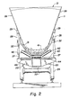
- FIG 2 is a diagrammatic cross-sectional view of a typical hopper car 11, the section being taken through one of the hoppers 21 of the hopper car.
- the hopper car 11 is of conventional construction including a main frame consisting of a center sill 22 and side beam members 23, which would be supported on trucks 24 in a conventional manner. While this particular form of basic rail car structure is illustrated, it will be understood that the hopper car may be constructed using other known techniques where the center sill is eliminated.
- the hopper body 21 may be rectangular as viewed from the top, including planar side walls 26 and corresponding planar end walls. As seen in Figures 2 and 3, the hopper walls are inclined at least 65° and preferably at least 70° from the horizontal to assure the complete discharge of the aggregate or other material from the hopper.
- the hopper is supported by means of longitudinal channel stringers 27 supported atthe outer ends of the side beams 23, in turn supporting vertical posts 28 which bear on angle brackets 29 suitably secured to the side walls 26 of the hopper.
- the bottom discharge opening 31 of the hopper then is quite wide and quite long, the width being at least 50% of the distance between the hopper carwheels as illustrated in Figure 2, and the length being at least 80% of the longitudinal top dimension of the hopper as illustrated in Figure 3.
- the discharge opening is closed by a suitable clam shell gate 32 consisting of a pair of coacting members which are movable toward and away from each other in a direction transverse to the longitudinal axis of the hopper car.
- the hopper 21 is supported sufficiently high relative to the hopper car frame to allow for the support of the endless belt conveyor 40 as will now be described.
- the conveyor belt has a width substantially greaterthan that of the hopper discharge openings 31 about 33% greater for example, as illustrated in Figure 2.
- the supply belt 41 which is the upper run of the endless belt conveyor 40 is supported in the form of a trough by troughing idlers 42, which may be catenary troughing rollers. This trough of course confronts the discharge openings 31 of the several hoppers.
- the return belt 43 which is the return portion of the endless belt conveyor 40, is supported immediately under the supply belt in a flat condition by return idlers 44. As seen in Figure 2, the return idlers are split idlers mounted on either side of the car center sill 22 to support the return run 43 as close as possible to the upper surface of the center sill.
- the troughing idlers 42 are necessarily supported in catenary fashion to enable positioning of the supply run 41 as close as possible to the center sill. With this belt support arrangement, the entire hopper car structure will have the lowest possible centre of gravity.
- the clam shell gates 32 are preferably operated between the closed and opened positions by power means such as hydraulic cylinders (not shown) which may be operated under the control of suitable control valves to be described subsequently.
- power means such as hydraulic cylinders (not shown) which may be operated under the control of suitable control valves to be described subsequently.
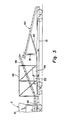
- the train conveyor 40 traverses the entire length of the hopper car portion of the unit train and a portion of the length of the trailer car 15 as best seen in Figure 3.
- the adjacent cars of the unit train have suitable support structures for supporting the train conveyor over the car couplers.
- the trailer car 15 is a multi-purpose car and, as best seen in Figure 3, may consist of a conventional flat-bed car carrying certain structures to be described.
- the portion of the train conveyor 40 which is carried on the trailer car, is a lift portion 45 which elevates the conveyed material for discharge onto a transfer conveyor 50.
- This lift portion 45 is supported by a suitable frame structure 46 of the trailer car.
- the transfer conveyor 50 is an elongated endless belt conveyor, having a length of about thirty feet (9 meters) for example, which is carried at the rearward end of the trailer car 15.
- the forward end of the transfer conveyor is mounted on a post 51 underlying the rearward end of the train conveyor 40, with the transfer conveyor being supported to rotate relative to the vertical axis of the post 51 to position its discharge end at any desired point.
- the transfer conveyor is carried as illustrated in Figure 3 in longitudinal alignment with the trailer car.
- the transfer conveyor is also pivotable, relative to the post 51, about a horizontal transverse axis, so that the rearward end of the conveyor may be elevated as desired; and this is accomplished by means of a hydraulic lift cylinder 52.
- the transfer conveyor is preferably provided with hydraulically powered means (not shown) for rotating the conveyor relative to the axis of the post 51. In this manner the discharge end of the transfer conveyor can be positioned where desired, to discharge the material from the train conveyor 40 into other transport vehicles, onto another conveyor, onto piles adjacent to the track or onto the track behind the trailer car.
- the trailer car 15 may also carry power generating apparatus for operating the conveyor system described.
- the train conveyor 40 and the transfer conveyor 50 are preferably driven, by suitable electric motors; and the power for these motors may be generated by a suitable electric generator 55 driven by a suitable internal combustion engine 56 such as a diesel engine.
- the generator 55 may also provide power for auxiliary apparatus such as portable stacking conveyor to be described.
- the clam shell gates 32 for the hoppers will be quite long and heavy, and each gate of a pair of gates would be preferably operated by a pair of double acting hydraulic cylinders.
- the four cylinders would preferably be controlled simultaneously by a single hydraulic valve which may be a manual valve, or may be a solenoid actuated valve for example.
- High pressure hydraulic fluid for the operation of these gates 32 would be supplied from the trailer car 15 which would include a suitable electric motor driven hydraulic pump.
- the electric motor would receive its energy from the above mentioned generator 55.
- the controls for the hopper gates should be preferably located at the side of the hopper car in order to be conveniently actuated by a crew member. The controls so located would be either manually operable hydraulic valves or electric switch controls for operating the solenoid actuated valves.
- the hoppers will be emptied in sequence beginning with the hopper nearest the trailer car. It is desirable that the hopper gates be operated under the manual and visual control of a crew member to assure that one hopper is completely empty before the gates of the succeeding hopper are opened. Where the load is being dumped in a windrow, this operator may also assist in controlling the speed of the train by signalling the locomotive engineer to assure the efficient stacking of the windrow.
- the trailer car 15 may also include a suitable control panel or station for the operation and control of the several above described components incuding the generator 55, the generator driving engine 56, the motors for the train conveyor 40 and the transfer conveyor 50, the hydraulic mechanisms for both rotating and changing the height of the transfer conveyor, and possibly the mechanism for controlling the tension on the train conveyor 40.
- the train For the operation of the train conveyor 40, the train must be on a straight section of track, since the conveyor belt cannot accommodate any curves during use. During such use the conveyor must be appropriately tensioned; and this may be accomplished by a suitable hydraulically controlled system which is associated with the lift portion 45 of the conveyor carried on the trailer car 15. This belt tensioning system may be conventional and need not be described further here. During the transit of the train, some slack must be imparted to the train conveyor to allow the belt to flex at the coupling points and enable the train to negotiate curves without damage to the belt. The control for that belt tensioning sytem may also preferably be included in the above mentioned control panel carried on the trailer car.
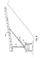
- Figure 4 of the drawing is a diagrammatic end view of the trailer car, omitting certain structures of the trailer car but illustrating the transfer conveyor 50 in position to deposit the bulk material into a windrow alongside the track.
- the windrow might have a height of ten feet (3 meters) for example and the apex must be sufficiently removed from the track to prevent the material from running onto the track.
- the material may be deposited in the windrow while the train is moving; and therefore the stretch of straight track must be sufficiently long to allow the train to move a sufficient distance to unload the entire load.
- the hopper gates might be operated in sequence starting from the rear of the train to unload the entire train.
- the train would have an unloading rate of 1000 tons per hour (907.2 M.T. per hour) so that an entire 800 ton (726 M.T.) train load can be deposited in a windrow alongside the track in approximately forty-five minutes.
- FIG. 5 of the drawing illustrates another method for unloading the train of the invention, which may be accomplished while the train is stationary.
- This method involves the use of a portable stacking conveyor 60 of a type which is commonly in use.
- This conveyor 60 is an elongated endless belt conveyor having a support frame 61 including support wheels 62 intermediate its ends, and having a receiving box 63 at its receiving end.
- This conveyor may be powered by a suitable electric motor; and may be connected to the above described generating system of the trailer car 15.
- Conceivably, such portable stacking conveyor could be carried with the self-unloading train of the invention; but more practically it would be transported to the unloading site by truck for example.
- Such portable stacking conveyor may be positioned relative to the trailer car to enable the stacking of an entire train load for example into a pile thirty feet (9 meters) high and forty feet (12 meters) away from the track.
- adjacent piles may be made by moving the portable stacking conveyor, for example.
- a particular feature and advantage of the invention is that the equipment and method are functionally independent of any particular kind of unloading facility and independent of unloading time.
- the train can be unloaded by the train crew without the necessity for any unloading facilities or equipment or personnel at the unloading site.
- aggregates are to be delivered to a highway construction site for example, advantage may be taken of the fact that railroads frequently parallel highways; and the aggregates may be unloaded either on railroad right of way or highway right of way adjacent to the railroad and very close to the point of use of the aggregates. Additionally such aggregates may be delivered to that site weeks or even months ahead of the time that the aggregates will be used by the highway contractor.
- a unit train as above described may be relatively small in terms of the number of hopper cars and overall train load; and this may be desirable to enable the train to be pulled by a relatively low powered locomotive.
- two or more such unit trains may be coupled together and either pulled by a larger locomotive or by multiple locomotives, one located at the front of the train and one located at the rear.
- An important advantage of the invention is that such unit trains may be utilized to their maximum capacity, since there is no need for the train to remain on a siding for several days or longer waiting to be unloaded.
- An ancillary advantage to the receiver of the materials is that he has much more flexibility in arranging for the transfer of the materials from the rail siding to his storage or use location. He can schedule the use of his equipment much more efficiently, and need not be concerned about the cost of idle hopper cars sitting on a siding.
- Another feature and advantage of the invention is that several different kinds or grades of material can be shipped on the same train. Since the hoppers are unloaded sequentially, a first kind of material may be loaded onto the front portion of the train, a second kind of material may be loaded onto a middle portion of the train, and a third kind of material may be loaded onto the rear portion of the train. If the train is unloaded in a windrow, the three different kinds of materials will be located in identifiable sections of the windrow. If the material is unloaded in piles by a portable stacking conveyor, by moving the conveyor or the train or both, the different kinds of material may be stacked in separate piles.
- An important advantage of the invention is that it takes advantage of the efficiencies of rail transportation. It allows for twenty-four hour operation of the rail facilities and equipment while requiring no specialized unloading facility.
- An overall feature and advantage of the invention is that it provides for maximum economy in the business of transporting bulk materials since it utilizes the rail transportation to maximum advantage, utilizes the equipment to the fullest extent by eliminating idle time, and utilizes the crew more efficiently.
Landscapes
- Engineering & Computer Science (AREA)
- Architecture (AREA)
- Civil Engineering (AREA)
- Structural Engineering (AREA)
- Disintegrating Or Milling (AREA)
- Loading Or Unloading Of Vehicles (AREA)
- Ship Loading And Unloading (AREA)
- Machines For Laying And Maintaining Railways (AREA)
Claims (10)
dadurch gekennzeichnet, daß alle Wände (26) jedes Trichters (21) um wenigstens 65° von der Horizontalen geneigt sind; daß jeder Wagen (11, 12, 13) eine Mittelschwelle (22) besitzt; daß der Rücklauf (43) des genannten Förderbandes durch geteilte Rücklaufspannrollen (44) abgestützt ist, die an den seitlichen Seiten der genannten Mittelschwellen (22) angeordnet sind; und daß der Zufuhrlauf (41) des genannten Förderers (40) durch Rollen (42) mit einer seil- bzw. kettenlinienförmigen Muldung abgestützt ist, die unmittelbar oberhalb des genannten Rücklaufs (43) angeordnet sind.
Priority Applications (1)
| Application Number | Priority Date | Filing Date | Title |
|---|---|---|---|
| AT86304284T ATE51910T1 (de) | 1985-06-06 | 1986-06-05 | Selbstentladerzug fuer sturzgueter. |
Applications Claiming Priority (2)
| Application Number | Priority Date | Filing Date | Title |
|---|---|---|---|
| US74169585A | 1985-06-06 | 1985-06-06 | |
| US741695 | 1985-06-06 |
Publications (2)
| Publication Number | Publication Date |
|---|---|
| EP0206590A1 EP0206590A1 (de) | 1986-12-30 |
| EP0206590B1 true EP0206590B1 (de) | 1990-04-11 |
Family
ID=24981787
Family Applications (1)
| Application Number | Title | Priority Date | Filing Date |
|---|---|---|---|
| EP86304284A Expired - Lifetime EP0206590B1 (de) | 1985-06-06 | 1986-06-05 | Selbstentladerzug für Sturzgüter |
Country Status (4)
| Country | Link |
|---|---|
| EP (1) | EP0206590B1 (de) |
| AT (1) | ATE51910T1 (de) |
| AU (1) | AU585616B2 (de) |
| DE (1) | DE3670320D1 (de) |
Families Citing this family (7)
| Publication number | Priority date | Publication date | Assignee | Title |
|---|---|---|---|---|
| AT398213B (de) * | 1989-10-31 | 1994-10-25 | Plasser Bahnbaumasch Franz | Maschine zum aufnehmen und verteilen des bettungsschotters |
| US5277538A (en) * | 1991-03-26 | 1994-01-11 | Franz Plasser Bahnbaumaschinen-Industriegesellschaft M.B.H. | Loading car for bulk material |
| CZ279535B6 (cs) * | 1993-05-07 | 1995-05-17 | Franz Plasser Bahnbaumaschinen-Industriegesellschaft M.B.H. | Nákladní vůz pro přepravu a ukládání sypkého materiálu |
| SE539468C2 (sv) * | 2015-06-03 | 2017-09-26 | Railcare Group Ab | Ballastmatningsanordning och förfarande för matning av ballast |
| CN213770217U (zh) * | 2020-10-10 | 2021-07-23 | 河南跃薪时代新能源科技有限公司 | 纯电动矿用自卸车 |
| CN114852116B (zh) * | 2022-01-24 | 2024-09-20 | 中国铁建高新装备股份有限公司 | 一种物料车及其作业方法 |
| CN117719827A (zh) * | 2023-12-27 | 2024-03-19 | 中冶焦耐(大连)工程技术有限公司 | 一种防侧翻型带式输送机卸料车 |
Family Cites Families (6)
| Publication number | Priority date | Publication date | Assignee | Title |
|---|---|---|---|---|
| GB142569A (en) * | 1919-02-10 | 1920-05-10 | Edward Wayne Shutt | Improvements in or relating to apparatus for the construction of railway road beds |
| US1455602A (en) * | 1922-11-02 | 1923-05-15 | George A Curlee | Dumping apparatus |
| US2989930A (en) * | 1953-07-09 | 1961-06-27 | Flowers Henry Fort | Railroad ballast car body and ballast spreader mechanism |
| PL86710B1 (de) * | 1973-10-06 | 1976-06-30 | ||
| AT370152B (de) * | 1981-04-16 | 1983-03-10 | Plasser Bahnbaumasch Franz | Fahrbare anlage zur herstellung einer zwischen planum und schotterbett eines gleises verlaufenden schutzschichte |
| FR2508950A1 (fr) * | 1981-07-02 | 1983-01-07 | Bouvot Marc | Machine et procede permettant le remblaiement axial des breches ouvertes pour travaux sur les voies ferrees en service et le garnissage de pistes le long des voies ferrees |
-
1986
- 1986-06-05 AT AT86304284T patent/ATE51910T1/de not_active IP Right Cessation
- 1986-06-05 EP EP86304284A patent/EP0206590B1/de not_active Expired - Lifetime
- 1986-06-05 AU AU58410/86A patent/AU585616B2/en not_active Expired
- 1986-06-05 DE DE8686304284T patent/DE3670320D1/de not_active Expired - Lifetime
Also Published As
| Publication number | Publication date |
|---|---|
| DE3670320D1 (de) | 1990-05-17 |
| AU585616B2 (en) | 1989-06-22 |
| EP0206590A1 (de) | 1986-12-30 |
| ATE51910T1 (de) | 1990-04-15 |
| AU5841086A (en) | 1986-12-11 |
Similar Documents
| Publication | Publication Date | Title |
|---|---|---|
| US4925356A (en) | Self-unloading train for bulk commodities | |
| CA2102007C (en) | A loading wagon for the transport of bulk material | |
| US4809617A (en) | Box car | |
| US4795301A (en) | Low-center-of-gravity self-unloading train for bulk commodities | |
| MX2015001054A (es) | Sistema de descarga de propante y un contenedor para uso en tal sistema de descarga de propante. | |
| MX2015001055A (es) | Aparato de apoyo para mover propante de un contenedor en un sistema de descarga de propante. | |
| US5197845A (en) | Conveyor system for self-unloading train | |
| US6073561A (en) | Box car for transporting bulk material | |
| EP0206590B1 (de) | Selbstentladerzug für Sturzgüter | |
| CN115743187A (zh) | 一种分布驱动式矿用轨道运输系统及其方法 | |
| CN1019661B (zh) | 散装货物装卸车 | |
| US5029532A (en) | Control cab | |
| US5174211A (en) | Panel track delivery system | |
| US4958977A (en) | System for the transport of bulk commodities | |
| US10717451B2 (en) | Aggregate train and methods of loading and unloading | |
| CZ279535B6 (cs) | Nákladní vůz pro přepravu a ukládání sypkého materiálu | |
| US5215422A (en) | Training idler assembly for self-unloading trains | |
| US3307718A (en) | Multicar bulk transporter and method | |
| RU2136883C1 (ru) | Способ транспортирования горной массы из карьеров и шахт (варианты) | |
| EP2739787B1 (de) | Behälter, schienenfahrzeug mit einem solchen behälter und verfahren zum be- und entladen von aggregaten auf bzw. von diesem schienentransportfahrzeug | |
| AU621086B2 (en) | Freight discharge of railway wagons | |
| SK280375B6 (sk) | Súprava na zachytávanie a prepravu sypkého materiá | |
| US5387073A (en) | Shuttlecar unloading device | |
| CN112919160A (zh) | 一种火车货运翻车机卸车车厢余料转运方法及系统 | |
| US4032026A (en) | Bulk hauling freight car unloading apparatus and method of operation |
Legal Events
| Date | Code | Title | Description |
|---|---|---|---|
| PUAI | Public reference made under article 153(3) epc to a published international application that has entered the european phase |
Free format text: ORIGINAL CODE: 0009012 |
|
| AK | Designated contracting states |
Kind code of ref document: A1 Designated state(s): AT BE CH DE FR GB IT LI LU NL SE |
|
| 17P | Request for examination filed |
Effective date: 19870411 |
|
| 17Q | First examination report despatched |
Effective date: 19880526 |
|
| GRAA | (expected) grant |
Free format text: ORIGINAL CODE: 0009210 |
|
| AK | Designated contracting states |
Kind code of ref document: B1 Designated state(s): AT BE CH DE FR GB IT LI LU NL SE |
|
| REF | Corresponds to: |
Ref document number: 51910 Country of ref document: AT Date of ref document: 19900415 Kind code of ref document: T |
|
| REF | Corresponds to: |
Ref document number: 3670320 Country of ref document: DE Date of ref document: 19900517 |
|
| ITF | It: translation for a ep patent filed | ||
| ET | Fr: translation filed | ||
| PLBE | No opposition filed within time limit |
Free format text: ORIGINAL CODE: 0009261 |
|
| STAA | Information on the status of an ep patent application or granted ep patent |
Free format text: STATUS: NO OPPOSITION FILED WITHIN TIME LIMIT |
|
| 26N | No opposition filed | ||
| ITTA | It: last paid annual fee | ||
| EPTA | Lu: last paid annual fee | ||
| EAL | Se: european patent in force in sweden |
Ref document number: 86304284.2 |
|
| PGFP | Annual fee paid to national office [announced via postgrant information from national office to epo] |
Ref country code: LU Payment date: 19961101 Year of fee payment: 11 |
|
| PGFP | Annual fee paid to national office [announced via postgrant information from national office to epo] |
Ref country code: CH Payment date: 19961210 Year of fee payment: 11 |
|
| PG25 | Lapsed in a contracting state [announced via postgrant information from national office to epo] |
Ref country code: LU Free format text: LAPSE BECAUSE OF NON-PAYMENT OF DUE FEES Effective date: 19970605 |
|
| PG25 | Lapsed in a contracting state [announced via postgrant information from national office to epo] |
Ref country code: LI Free format text: LAPSE BECAUSE OF NON-PAYMENT OF DUE FEES Effective date: 19970630 Ref country code: CH Free format text: LAPSE BECAUSE OF NON-PAYMENT OF DUE FEES Effective date: 19970630 |
|
| REG | Reference to a national code |
Ref country code: CH Ref legal event code: PL |
|
| PGFP | Annual fee paid to national office [announced via postgrant information from national office to epo] |
Ref country code: GB Payment date: 19990602 Year of fee payment: 14 |
|
| PGFP | Annual fee paid to national office [announced via postgrant information from national office to epo] |
Ref country code: SE Payment date: 19990607 Year of fee payment: 14 Ref country code: DE Payment date: 19990607 Year of fee payment: 14 |
|
| PGFP | Annual fee paid to national office [announced via postgrant information from national office to epo] |
Ref country code: FR Payment date: 19990610 Year of fee payment: 14 |
|
| PGFP | Annual fee paid to national office [announced via postgrant information from national office to epo] |
Ref country code: AT Payment date: 19990614 Year of fee payment: 14 |
|
| PGFP | Annual fee paid to national office [announced via postgrant information from national office to epo] |
Ref country code: NL Payment date: 19990628 Year of fee payment: 14 |
|
| PGFP | Annual fee paid to national office [announced via postgrant information from national office to epo] |
Ref country code: BE Payment date: 19990819 Year of fee payment: 14 |
|
| PG25 | Lapsed in a contracting state [announced via postgrant information from national office to epo] |
Ref country code: GB Free format text: LAPSE BECAUSE OF NON-PAYMENT OF DUE FEES Effective date: 20000605 Ref country code: AT Free format text: LAPSE BECAUSE OF NON-PAYMENT OF DUE FEES Effective date: 20000605 |
|
| PG25 | Lapsed in a contracting state [announced via postgrant information from national office to epo] |
Ref country code: SE Free format text: LAPSE BECAUSE OF NON-PAYMENT OF DUE FEES Effective date: 20000606 |
|
| PG25 | Lapsed in a contracting state [announced via postgrant information from national office to epo] |
Ref country code: BE Free format text: LAPSE BECAUSE OF NON-PAYMENT OF DUE FEES Effective date: 20000630 |
|
| BERE | Be: lapsed |
Owner name: SNEAD WILLIAM BRAZELTON Effective date: 20000630 Owner name: SNEAD EDWIN DESTEIGER Effective date: 20000630 |
|
| PG25 | Lapsed in a contracting state [announced via postgrant information from national office to epo] |
Ref country code: NL Free format text: LAPSE BECAUSE OF NON-PAYMENT OF DUE FEES Effective date: 20010101 |
|
| GBPC | Gb: european patent ceased through non-payment of renewal fee |
Effective date: 20000605 |
|
| EUG | Se: european patent has lapsed |
Ref document number: 86304284.2 |
|
| PG25 | Lapsed in a contracting state [announced via postgrant information from national office to epo] |
Ref country code: FR Free format text: LAPSE BECAUSE OF NON-PAYMENT OF DUE FEES Effective date: 20010228 |
|
| NLV4 | Nl: lapsed or anulled due to non-payment of the annual fee |
Effective date: 20010101 |
|
| REG | Reference to a national code |
Ref country code: FR Ref legal event code: ST |
|
| PG25 | Lapsed in a contracting state [announced via postgrant information from national office to epo] |
Ref country code: DE Free format text: LAPSE BECAUSE OF NON-PAYMENT OF DUE FEES Effective date: 20010403 |
|
| PG25 | Lapsed in a contracting state [announced via postgrant information from national office to epo] |
Ref country code: IT Free format text: LAPSE BECAUSE OF NON-PAYMENT OF DUE FEES Effective date: 20050605 |