EP0206583A2 - Gangway construction for vehicles - Google Patents
Gangway construction for vehicles Download PDFInfo
- Publication number
- EP0206583A2 EP0206583A2 EP86304248A EP86304248A EP0206583A2 EP 0206583 A2 EP0206583 A2 EP 0206583A2 EP 86304248 A EP86304248 A EP 86304248A EP 86304248 A EP86304248 A EP 86304248A EP 0206583 A2 EP0206583 A2 EP 0206583A2
- Authority
- EP
- European Patent Office
- Prior art keywords
- hood
- vehicles
- structures
- pressers
- positioning
- Prior art date
- Legal status (The legal status is an assumption and is not a legal conclusion. Google has not performed a legal analysis and makes no representation as to the accuracy of the status listed.)
- Granted
Links
Images


Classifications
-
- B—PERFORMING OPERATIONS; TRANSPORTING
- B61—RAILWAYS
- B61D—BODY DETAILS OR KINDS OF RAILWAY VEHICLES
- B61D17/00—Construction details of vehicle bodies
- B61D17/04—Construction details of vehicle bodies with bodies of metal; with composite, e.g. metal and wood body structures
- B61D17/20—Communication passages between coaches; Adaptation of coach ends therefor
- B61D17/22—Communication passages between coaches; Adaptation of coach ends therefor flexible, e.g. bellows
Definitions
- the present invention relates to a gangway construction for vehicles.
- an object of the present invention is to provide a gangway construction for vehicles, which is capable of automatically and positively carrying out connecting and disconnecting operations of divided hood structures not only on straight railways but also on curved railways, without any manual works.
- a gangway construction for vehicles comprises divided hood structures each of which has a first end and a second end, the first ends of the respective hood structures being fixed to the vehicles, and the second ends thereof being made to face each other, a plurality of hood pressers provided between upper sides of metal frames on the release side and the vehicles and between lower sides thereof and the vehicles for urging the hood structures in their extension direction upon coupling operation, the plurality of hood pressers being arranged in horizontal planes in convergent relation, and positioning members for guiding and engaging each other upon the mutual approach to effect a centering action, the positioning members being provided in the metal frames of the free sides of the divided hood structures.
- the hood structures are kept connected relative to each other in the widthwise direction of the vehicles without any relative shift. Also, the arrangement of the hood pressers in convergent relation makes it possible to always urge the hood structures toward the centerline of between vehicles. Also, by separating the couplers to separate the vehicles, the hood structures are automatically separated while being held at the vehicles, since the hood structures are connected in pressing contact by the hood pressers.
- hood structures 3 and 4 divided into two sections in a longitudinal direction of two railway cars or vehicles 1 and 2 to be connected each other are provided between opening portions, facing each other, of the two vehicles 1 and 2.
- a vehicle side metal frame of each of the hood structures 3 and 4 is fixed to the opening portion of the associated vehicle.
- the two vehicles 1 and 2 may be separated form each other by disconnecting couplers 5 and 6 so that the hood structures 3 and 4 may be separated from each other along central dividing and facing portions.
- the couplers 5 and 6 may be connected to each other so that the facing portions of the hood structures 3 and 4 may be pressingly connected to each other.
- a gangway portion for between the two vehicles is defined and covered by the two hood structures 3 and 4.
- a stationary metal frame 7 of the hood structure 3 is formed in an annular shape to define the gangway and is fixed to the opening portion of the vehicle 1 by bolts or any other fastening means.
- a free side metal frame 8 is formed in an annular shape to define the gangway in cooperation with the stationary metal frame 7.
- a hood member 9 which is in the form of a bellows extendable as desired is laid between the free side metal frame 8 and the stationary metal frame 7.
- the free side metal frame 8 is suspended by metal frame suspenders 10 such as coil springs or the like laid between both sides of the metal frame and the opening portion of the vehicle.
- An upper support plate 11 is provided on a top of the free side metal frame 8. The detail thereof is shown in Fig. 3.
- a plurality (three in the embodiment) of hood pressers 12, 13 and 14 are arranged in a horizontal plane in convergent relation between the upper support plate 11 and the vehicle 1.
- Each of the hood pressers 12, 13 and 14 has a coil spring provided around a shaft unit made up of an extendable cylinder and piston so as to be normally extended and be contractable when it is compressed.
- Mount members 15 and 16 each of which is made up of a universal joint are provided at opposite ends of each hood pressers, whereby the opening portion of the vehicle 1 is coupled to the upper support plate 11 of the free side metal frame 8.
- the central hood presser 13 is arranged in alignment with a centerline of the vehicle 1, whereas the both side hood pressers 12 and 14 are arranged in a convergent manner so that the pressers 12 and 14 are inclined in a direction opposite to each other with respect to the centerline of the vehicle 1.
- a pressing action of partial component of force exerted in the transverse direction of the vehicle by the both side hood pressers 12 and 14 causes the free side metal frame 8 to be urged to be returned back to the central position of the gangway in the case where the center of the free side metal frame 8 is displaced from the centerline of the gangway in the widthwise direction.
- hood pressers 19 and 20 are arranged in a horizontal plane in convergent relation between the bottom support plates 17 and 18 and the vehicle 1 and are located on both sides of the coupler 5.
- the hood pressers 19 and 20 have the same structure as that of the above-described hood pressers 12, 13 and 14. Namely, the hood pressers 19 and 20 are coupled to between the opening portion of the vehicle 1 and the bottom support plates 17 and 18 of the free side metal frame 8 by means of mount members 21 and 22 such as universal joints.
- the two hood pressers 19 and 20 are arranged in a plane in a convergently inclined manner so as to have the same function as that of the convergently inclined hood pressers 12 and 14.
- the pressing forces of the respective hood pressers 12, 13, 14, 19 and 20 are selected so that, when the vehicles are coupled to each other, the free side metal frames 8 and 8a of the confronting hood structures 3 and 4 press against each other at a desired pressure.
- a seal member 23 made of elastic material for preventing rain drops from entering into the interior is provided over an entire circumference of a front face of free side metal frame 8, 8a of each hood structure 3, 4, as shown in Figs. 7 and 10.
- the pressing contact between the hood structures 3 and 4 causes the seal members 23, 23 to be held in intimate contact with each other to seal the interior of the gangway from the outside.
- a positioning projection 24 projected forwardly from an upper corner portion of the frame 8.
- Fixed to the positioning projection 24 are tapered vanes 24a whose proximal end portions are widened as shown in Figs. 8 and 9.
- an associated positioning hole 25 to be engaged with the positioning projection 24 is formed at a position in alignment with the positioning projection 24.
- the positioning hole 25 is made up of a cone- shaped guide portion 25a of guiding the introduction of the positioning projection 24 and an engagement hole portion 25b. In the same manner, another positioning hole 25 is formed in the release side metal frame 8 whereas a like positioning projection 24 is provided on the release side metal frame 8a.
- each pin 26 is loosely engaged with a hole 29a of a cylindrical bushing 29 made of, for example, resin and fixed within each receiver 28.
- An inner diameter of the hole 29a is somewhat greater than an outer diameter of the pin 26.
- a clearance or gap 31 is defined between a base plate 30 of the pin 26 and the top surface of the pin receiver 28.
- An up-and-down length of the clearance 31 is shorter than that of a clearance or gap 32 at the lower end of the pin 26.
- two ceiling panels 33 and 34 divided in the back and forth direction are provided with a front edge of the forward ceiling panel 33 fixed to the free side metal frame 8 and a rear edge of the rear ceiling panel 34 supported to the vehicle 1.
- the front portion of rear ceiling panel 34 is slidably laid on the top surface of the forward ceiling panel 33.
- two side panels 35 and 36 divided in the back and forth direction are provided on each side of the gangway with a front edge of the forward side panel 35 fixed to the free side metal frame 8 and a rear edge of the rear side panel 36 supported to the vehicle 1 rotatably in a plane.
- a front portion of the rear side panel 36 is held in sliding contact with the inner surface of the front side panel 35, whereas the rear side panel 36 is urged in the contact direction by a spring 37.
- the hood member 9 is suspended from the front side panel 36 by a suspender 38.
- two bridge plates 38 and 40 divided unit he back and fourth direction are provided at the bottom of the gangway.
- the front edge of the front bridge plate 39 is provided pivotably about the release side metal frame 8 to be risable but normally contact with the top surface of the rear bridge plate 40.
- the rear edge of the rear bridge plate 40 is provided pivotably about the body 1 end to be risable.
- Figs. 15 and 16 show a state in which the couplers 5 and 6 are disconnected from each other to thereby separate the vehicles 1 and 2. Under this state, the hood structures 3 and 4 are separated from each other and at the same time the upper portions thereof are extended by the spring force of the hood pressers 12, 13 and 14 whereas the bottom portions are restricted by the couplings between the pins 26 and the pin receivers 28. Thus, the upper portions are forwardly inclined as shown in Fig. 16.
- the two free side metal frame 8 and 8a are automatically guided so that their upper portions are held in contact with each other, since the two free side metal frames 8 and 8a and the couplers 5 and 6 are urged together toward the centerline by the convergently arranged hood pressers 12, 14, 19 and 20 and the positioning projections 24 are introduced into the positioning holes 25, as shown in Figs. 17 and 18.
- the upper portions of the free side metal frame 8 and 8a are pressed toward the opening portions of the vehicles against the spring reaction of the upper hood pressers 12, 13 and 14, so that the hood structures 3 and 4 are contracted.
- the positioning projections 24 are fully inserted into the positioning holes 25 to carry out the centering of the metal frames, and the centering of the couplers 5 and 6 causes the two release side metal frames 8 and 8a to be automatically centered and connected to each other.
- the pins 26 extending from the free side metal frames 8 and 8a are loosely engaged with the pin receivers 28 so that the lower portions of the free side metal frames 8 and 8a are pressed against the spring reaction of the hood pressers 19 and 20 to each other.
- the two hood structures 3 and 4 are prevented form sliding and shifting relative to each other in the right and left direction of the vehicles by the upper engagement between the positioning projections 24 and the positioning holes 25 and the lower engagement of the pins 26 and the pin receivers 28. Also, in the case where the hood structures 3 and 4 are vibrated in the right and left direction, the hood structures 3 and 4 are forced to return back to the central position by the convergently arranged hood pressers 12, 14, 19 and 20.
- the mutual pressure of the hood pressers withstands the vibration while keeping the coupled state of the hood structures 3 and 4.
- the hood structures 3 and 4 follows the various motions in a flexible integral manner to always keep the connected state without separation. It is, therefore, unnecessary to couple the two free side metal frames 8 and 8a of the hood structures 3 and 4 by inserting pins or by means of fastening members or the like. Since the seal members 23 and 23 of the release side metal frames 8 and 8a are held in intimate contact with each other by such coupling, the atmosphere or rain drops are completely prevented from entering into the interior to keep a good condition even for running on the commercial line or work shop line.
- the distal ends of the positioning projections 24 provided in the free side metal frames 8 and 8a are engaged with the tapered distal ends of the positioning holes 25, and by the subsequent approach the positioning projections 24 and guided to the deep central portions of the positioning holes 25 to thereby carry out the centering of the couplers 5 and 6, thus completing the coupling operation. Therefore, also in this case, the automatic and positive coupling may be ensured.
- the hood structures 3 and 4 are separated in the order opposite to that described above.
- the convergently arranged hood pressers 12, 14, 19 and 20 are directed to the free side metal frame as described above, it is possible to arrange these pressers in a convergent manner toward the vehicle. Furthermore, although, in the foregoing embodiment, the positioning of the free side metal frames on the lower side is performed by the engagement between the pins 26 and the pin receivers 28 on the coupler 5 side, that positioning may be performed by providing members similar to the positioning projections 24 and the positioning holes 25 formed on the upper side, instead of the pins 26 and the pin receivers 28.
Landscapes
- Engineering & Computer Science (AREA)
- Life Sciences & Earth Sciences (AREA)
- Wood Science & Technology (AREA)
- Mechanical Engineering (AREA)
- Platform Screen Doors And Railroad Systems (AREA)
- Body Structure For Vehicles (AREA)
- Superstructure Of Vehicle (AREA)
- Seal Device For Vehicle (AREA)
Abstract
Description
- The present invention relates to a gangway construction for vehicles.
- As in examples shown in Japanese Patent Publication No. 41426/84, most of conventional gangway constructions for vehicles or railway cars made so that upper portions of two-divided units are coupled to each other by hinge means or fastening means provided around the two-divided units.
- In the conventional constructions, it is necessary to manually carry out a setting work or removal work of pins of the hinge means or a fastening work or disconnecting work of the fastening means for the two-divided units, upon the connecting or disconnecting operation of the vehicles. Thus there is a problem such that it is impossible to automate the connecting and disconnecting operations.
- Accordingly, an object of the present invention is to provide a gangway construction for vehicles, which is capable of automatically and positively carrying out connecting and disconnecting operations of divided hood structures not only on straight railways but also on curved railways, without any manual works.
- According to the present invention, a gangway construction for vehicles comprises divided hood structures each of which has a first end and a second end, the first ends of the respective hood structures being fixed to the vehicles, and the second ends thereof being made to face each other, a plurality of hood pressers provided between upper sides of metal frames on the release side and the vehicles and between lower sides thereof and the vehicles for urging the hood structures in their extension direction upon coupling operation, the plurality of hood pressers being arranged in horizontal planes in convergent relation, and positioning members for guiding and engaging each other upon the mutual approach to effect a centering action, the positioning members being provided in the metal frames of the free sides of the divided hood structures.
- With such a gangway construction for vehicles, when the vehicles to be coupled to each other are made to approach each other, a centering operation is automatically carried out by the positioning members provided to the respective free side metal frames of the hood structures even though the free side metal frames are displaced relative to each other. When the vehicles are made to further approach, the free side metal frames are brought into contact with each other. When the vehicles are made to further approach to be coupled to each other, the free side metal frames are coupled against spring forces of the hood pressers. Therefore, under this coupled state, the free side metal frames of the two hood structures are kept in pressing contact by the spring forces of the hood pressers. At the same time, by the engagement of the positioning members, the hood structures are kept connected relative to each other in the widthwise direction of the vehicles without any relative shift. Also, the arrangement of the hood pressers in convergent relation makes it possible to always urge the hood structures toward the centerline of between vehicles. Also, by separating the couplers to separate the vehicles, the hood structures are automatically separated while being held at the vehicles, since the hood structures are connected in pressing contact by the hood pressers.
-
- Fig. 1 is a side elevational view showing one embodiment of the invention;
- Fig. 2 is an enlarged view showing a gangway construction for vehicles shown in Fig. 1, a left half of Fig. 2 being an elevational cross-section and a right half of Fig. 2 being a side elevation;
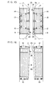
- Fig. 3 is an enlarged cross-sectional view showing an upper portion of the free side metal frame of the hood structure shown in Fig. 2;
- Fig. 4 is an enlarged plan view showing hood pressers located above the upper portion of the hood structure shown in Fig. 2;
- Fig. 5 is an enlarged plan view showing lower hood pressers below the hood structure shown in Fig. 2;
- Fig. 6 is an enlarged frontal view showing a state of the lower support of the free side metal frame shown in Fig. 2;
- Fig. 7 is a front elevational view of one free side metal frame provided with the positioning hole and projection;
- Fig. 8 is an enlarged side view showing the projection shown in Fig. 7;
- Fig. 9 is a front elevational view of the positioning projection shown in Fig. 8;
- Fig. 10 is a front elevational view of the other free side metal frame provided with the positioning hole and projection;
- Fig. 11 is a side view showing the positioning hole shown in Figs. 7 and 10;
- Fig. 12 is a front view showing the positioning hole shown in Fig. 11;
- Fig. 13 is an enlarged cross-sectional view showing a pin and pin receiver shown in Fig. 6;
- Fig. 14 is a view showing the gangway construction for vehicles shown in Fig. 1, a left half of Fig. 14 being a partial cross-sectional plan view and a right half of Fig. 14 is a plan view;
- Fig. 15 is a plan view showing a separated state of the hood structures;
- Fig. 16 is a side elevational view showing the separated state;
- Fig. 17 is a plan view showing a transient coupled state of the hood structures;
- Fig. 18 is a side elevational view showing the transient coupled state of the hood structures;
- Fig. 19 is a plan view showing a completely coupled state of the hood structures; and
- Fig. 20 is a side elevational view showing the completely coupled state of the hood structures.
- The preferred embodiments of the invention will now be described with reference to the accompanying drawings.
- Referring now to Fig. 1,
hood structures vehicles 1 and 2 to be connected each other are provided between opening portions, facing each other, of the twovehicles 1 and 2. A vehicle side metal frame of each of thehood structures vehicles 1 and 2 may be separated form each other by disconnectingcouplers 5 and 6 so that thehood structures couplers 5 and 6 may be connected to each other so that the facing portions of thehood structures hood structures - Since the two
hood structures hood structures 3 will be explained in detail with reference to Fig. 2. Astationary metal frame 7 of thehood structure 3 is formed in an annular shape to define the gangway and is fixed to the opening portion of the vehicle 1 by bolts or any other fastening means. Also, a freeside metal frame 8 is formed in an annular shape to define the gangway in cooperation with thestationary metal frame 7. Ahood member 9 which is in the form of a bellows extendable as desired is laid between the freeside metal frame 8 and thestationary metal frame 7. The freeside metal frame 8 is suspended bymetal frame suspenders 10 such as coil springs or the like laid between both sides of the metal frame and the opening portion of the vehicle. - An
upper support plate 11 is provided on a top of the freeside metal frame 8. The detail thereof is shown in Fig. 3. - As shown in Figs. 2 and 4, a plurality (three in the embodiment) of
hood pressers upper support plate 11 and the vehicle 1. Each of thehood pressers Mount members upper support plate 11 of the freeside metal frame 8. - The
central hood presser 13 is arranged in alignment with a centerline of the vehicle 1, whereas the both side hood pressers 12 and 14 are arranged in a convergent manner so that thepressers side hood pressers side metal frame 8 to be urged to be returned back to the central position of the gangway in the case where the center of the freeside metal frame 8 is displaced from the centerline of the gangway in the widthwise direction. - As shown in Fig. 6, two
bottom support plates coupler 5 are provided at a bottom of the freeside metal frame 8. As shown in Figs. 2 and 5, a plurality (two in the embodiment) ofhood pressers bottom support plates coupler 5. The hood pressers 19 and 20 have the same structure as that of the above-described hood pressers 12, 13 and 14. Namely, thehood pressers bottom support plates side metal frame 8 by means ofmount members hood pressers inclined hood pressers side metal frames hood structures - A
seal member 23 made of elastic material for preventing rain drops from entering into the interior is provided over an entire circumference of a front face of freeside metal frame hood structure hood structures seal members - Furthermore, as shown in Fig. 7, to the front face of the free
side metal frame 8, there is fixedly provided apositioning projection 24 projected forwardly from an upper corner portion of theframe 8. Fixed to thepositioning projection 24 are taperedvanes 24a whose proximal end portions are widened as shown in Figs. 8 and 9. - In the release
side metal frame 8a of thehood structure 4 confrontingprojection 24, an associatedpositioning hole 25 to be engaged with thepositioning projection 24 is formed at a position in alignment with thepositioning projection 24. - The
positioning hole 25 is made up of a cone- shapedguide portion 25a of guiding the introduction of thepositioning projection 24 and anengagement hole portion 25b. In the same manner, anotherpositioning hole 25 is formed in the releaseside metal frame 8 whereas alike positioning projection 24 is provided on the releaseside metal frame 8a. - As shown in Fig. 6, at the undersurface of the free
side metal frame 8, there are securely formed right and leftpins coupler 5 and extending downwardly. As shown in Figs. 5 and 6, on the top surface of thecoupler 5, there is fixedly provided amount plate 27 to whichpin receivers pins pins - Details of the
pins 26 and thepin receivers 28 will be described with reference to Fig. 13. Eachpin 26 is loosely engaged with ahole 29a of acylindrical bushing 29 made of, for example, resin and fixed within eachreceiver 28. An inner diameter of thehole 29a is somewhat greater than an outer diameter of thepin 26. In the normal condition, a clearance orgap 31 is defined between abase plate 30 of thepin 26 and the top surface of thepin receiver 28. An up-and-down length of theclearance 31 is shorter than that of a clearance orgap 32 at the lower end of thepin 26. - In the ceiling which defines the gangway within the
hood structure 3, as shown in Fig. 2, twoceiling panels forward ceiling panel 33 fixed to the freeside metal frame 8 and a rear edge of therear ceiling panel 34 supported to the vehicle 1. The front portion ofrear ceiling panel 34 is slidably laid on the top surface of theforward ceiling panel 33. As shown in Fig. 14, twoside panels forward side panel 35 fixed to the freeside metal frame 8 and a rear edge of therear side panel 36 supported to the vehicle 1 rotatably in a plane. - A front portion of the
rear side panel 36 is held in sliding contact with the inner surface of thefront side panel 35, whereas therear side panel 36 is urged in the contact direction by aspring 37. Thehood member 9 is suspended from thefront side panel 36 by asuspender 38. - As shown in Fig. 2, two
bridge plates front bridge plate 39 is provided pivotably about the releaseside metal frame 8 to be risable but normally contact with the top surface of therear bridge plate 40. Also, the rear edge of therear bridge plate 40 is provided pivotably about the body 1 end to be risable. - The operation of the embodiment of the invention will now be described.
- Figs. 15 and 16 show a state in which the
couplers 5 and 6 are disconnected from each other to thereby separate thevehicles 1 and 2. Under this state, thehood structures hood pressers pins 26 and thepin receivers 28. Thus, the upper portions are forwardly inclined as shown in Fig. 16. - When the two vehicle are made to approach each other form the separated state for coupling the vehicles, the two free
side metal frame side metal frames couplers 5 and 6 are urged together toward the centerline by the convergently arrangedhood pressers positioning projections 24 are introduced into the positioning holes 25, as shown in Figs. 17 and 18. When the vehicles are made to further approach each other, the upper portions of the freeside metal frame upper hood pressers hood structures positioning projections 24 are fully inserted into the positioning holes 25 to carry out the centering of the metal frames, and the centering of thecouplers 5 and 6 causes the two releaseside metal frames pins 26 extending from the freeside metal frames pin receivers 28 so that the lower portions of the freeside metal frames hood pressers hood structures positioning projections 24 and the positioning holes 25 and the lower engagement of thepins 26 and thepin receivers 28. Also, in the case where thehood structures hood structures hood pressers - With respect to the vibration of the vehicles in the back and forth direction, the mutual pressure of the hood pressers withstands the vibration while keeping the coupled state of the
hood structures - Even though the vehicles would be shifted relative to each other due to various running motions such as rolling, pitching and yawing not only on the straight rails but also curve rails, the
hood structures side metal frames hood structures seal members side metal frames - Incidentally, in the case where the vehicles are connected to each other on the curved rails, the distal ends of the
positioning projections 24 provided in the freeside metal frames positioning projections 24 and guided to the deep central portions of the positioning holes 25 to thereby carry out the centering of thecouplers 5 and 6, thus completing the coupling operation. Therefore, also in this case, the automatic and positive coupling may be ensured. - When the
couplers 5 and 6 are separated to release the vehicles which have been held in the coupled state, thehood structures - Although the convergently arranged
hood pressers pins 26 and thepin receivers 28 on thecoupler 5 side, that positioning may be performed by providing members similar to thepositioning projections 24 and the positioning holes 25 formed on the upper side, instead of thepins 26 and thepin receivers 28.
Claims (9)
Applications Claiming Priority (2)
| Application Number | Priority Date | Filing Date | Title |
|---|---|---|---|
| JP135010/85 | 1985-06-19 | ||
| JP60135010A JPS61291265A (en) | 1985-06-19 | 1985-06-19 | Connecting hood for car |
Publications (3)
| Publication Number | Publication Date |
|---|---|
| EP0206583A2 true EP0206583A2 (en) | 1986-12-30 |
| EP0206583A3 EP0206583A3 (en) | 1987-05-20 |
| EP0206583B1 EP0206583B1 (en) | 1992-04-15 |
Family
ID=15141818
Family Applications (1)
| Application Number | Title | Priority Date | Filing Date |
|---|---|---|---|
| EP86304248A Expired EP0206583B1 (en) | 1985-06-19 | 1986-06-04 | Gangway construction for vehicles |
Country Status (7)
| Country | Link |
|---|---|
| US (1) | US4765249A (en) |
| EP (1) | EP0206583B1 (en) |
| JP (1) | JPS61291265A (en) |
| AU (1) | AU562853B2 (en) |
| CA (1) | CA1275365C (en) |
| DE (1) | DE3684818D1 (en) |
| SG (1) | SG65293G (en) |
Cited By (9)
| Publication number | Priority date | Publication date | Assignee | Title |
|---|---|---|---|---|
| EP0329031A1 (en) * | 1988-02-12 | 1989-08-23 | HÜBNER Gummi- und Kunststoff GmbH | Protection of the passage between coupled articulated railway vehicles |
| EP0330742A3 (en) * | 1988-03-04 | 1989-10-25 | Hubner Gummi- Und Kunststoff Gmbh | Communication passage between rail vehicles |
| WO1995006580A1 (en) * | 1993-09-03 | 1995-03-09 | Sig Schweizerische Industrie-Gesellschaft | Passage device between two coupled vehicles |
| WO1998000327A1 (en) * | 1996-07-01 | 1998-01-08 | Hübner Gummi- Und Kunststoff Gmbh | Communication point between two vehicles flexibly connected to each other, e.g. railway coaches or underground coaches |
| US6009813A (en) * | 1996-07-01 | 2000-01-04 | Hubner Gummi - Und Kunststoff | Connection between two vehicles hinged to one another, e.g. railway coaches or underground coaches |
| RU2384420C2 (en) * | 2006-12-23 | 2010-03-20 | ХЮБНЕР ГмбХ | Device to prevent superextension of fold or wavy crimp element separated by central frame of fold or wavy corrugated casing |
| CN103434519A (en) * | 2013-08-19 | 2013-12-11 | 长春轨道客车股份有限公司 | Through passage tightening pull rod assembly in bus transport process |
| CN110406335A (en) * | 2018-04-28 | 2019-11-05 | 比亚迪股份有限公司 | bellows, bellows assemblies and vehicles |
| EP3771606A1 (en) * | 2019-08-02 | 2021-02-03 | Dellner Couplers AB | Gangway for connecting a first car of a multi-car vehicle to a second car |
Families Citing this family (20)
| Publication number | Priority date | Publication date | Assignee | Title |
|---|---|---|---|---|
| AU573399B2 (en) * | 1985-11-05 | 1988-06-09 | Sumitomo Rubber Industries, Ltd. | Radial tyre |
| JPH02136369A (en) * | 1988-11-17 | 1990-05-24 | Yukio Uozumi | Connecting awning structure for vehicle |
| KR960705710A (en) * | 1994-10-03 | 1996-11-08 | 게랄트 루크 · 알. 하베니스 | INNER LINING FOR GANGWAYS BETWEEN RAIL VEHICLES |
| US5823117A (en) * | 1995-05-16 | 1998-10-20 | Fiat-Sig Schienenfahrzeuge Ag | Passenger passageway for rail vehicles |
| JPH09221026A (en) * | 1996-02-19 | 1997-08-26 | Kawasaki Heavy Ind Ltd | Vehicle connecting hood |
| JP3437707B2 (en) * | 1996-03-26 | 2003-08-18 | 日本車輌製造株式会社 | Vehicle-connected hood device |
| KR200245222Y1 (en) * | 2001-03-08 | 2001-09-26 | 이은숙 | Gangway diaphragm structure for a railway vehicle |
| AT413684B (en) * | 2002-06-17 | 2006-05-15 | Siemens Sgp Verkehrstech Gmbh | REPLACEMENT BY FRONT TRANSITION |
| DE502004002531D1 (en) * | 2004-03-24 | 2007-02-15 | Huebner Gmbh | Bellows a transition between the vehicle boxes of two interconnected vehicles, with a shock absorbing frame. |
| ES2344607T3 (en) * | 2006-06-09 | 2010-09-01 | Hubner Gmbh | ARTICULATED VEHICLE ABLE TO BE FORMED COUPLING VARIOUS PARTS OF VEHICLE. |
| DE202006009083U1 (en) * | 2006-06-09 | 2007-10-18 | Hübner GmbH | Coupling of several vehicle parts articulated vehicle |
| DE502007001734D1 (en) * | 2007-06-14 | 2009-11-26 | Huebner Gmbh | Two articulated vehicles coupled together with a transition with at least one bellows and a coupling device comprising two coupling elements |
| FR2930927B1 (en) * | 2008-05-06 | 2010-05-14 | Lohr Ind | INTERCIRCULATION PASSAGE BETWEEN AT LEAST TWO ROAD MODULES CONNECTED BETWEEN THEM IN A DISSOCIABLE WAY TO FORM A ROW OR A ROAD TRAIN. |
| US8201503B2 (en) * | 2009-01-28 | 2012-06-19 | Railplan International, Inc. | Railroad car diaphragm |
| IL201185A0 (en) * | 2009-09-24 | 2010-05-17 | Yoel Bachar | Articulated modular transportation vehicle having improved accessibility |
| CN105151058A (en) * | 2015-09-24 | 2015-12-16 | 长春轨道客车股份有限公司 | Inner-windshield connecting method for motor train unit |
| US11267492B2 (en) * | 2019-06-14 | 2022-03-08 | HUBNER Manufacturing Corp | Rubber suspension unit of a diaphragm assembly for passage between rail cars |
| EP4019363A1 (en) | 2020-12-28 | 2022-06-29 | Bombardier Transportation GmbH | Controlled roof drainage via the bellows |
| CN113442958B (en) * | 2021-07-22 | 2025-04-11 | 中车长春轨道客车股份有限公司 | A high-speed train reconnection end anti-ice and snow device |
| PL4410630T3 (en) * | 2023-02-02 | 2025-07-07 | HÜBNER GmbH & Co. KG | Automatic coupling |
Family Cites Families (19)
| Publication number | Priority date | Publication date | Assignee | Title |
|---|---|---|---|---|
| US443075A (en) * | 1890-12-16 | Railroad-car | ||
| US417567A (en) * | 1889-12-17 | keehbiel | ||
| US946875A (en) * | 1910-01-18 | Nat Malleable Castings Co | Radial draft-gear and vestibule. | |
| DE293697C (en) * | ||||
| US474966A (en) * | 1892-05-17 | Vestibule for cars | ||
| US440615A (en) * | 1890-11-18 | Railway-car | ||
| FR727102A (en) * | 1931-02-05 | 1932-06-13 | Renar Henri Joseph | Improvements to intercirculation bellows for railway cars |
| US2337081A (en) * | 1940-08-02 | 1943-12-21 | Gen Motors Corp | Railway car diaphragm construction |
| US2645517A (en) * | 1950-04-19 | 1953-07-14 | Viberti Societa Per Azioni Off | Articulated vehicle body connection |
| GB810734A (en) * | 1956-02-28 | 1959-03-25 | George Spencer Moulton & Co | Improvements in and relating to railway vehicles |
| US2931317A (en) * | 1957-04-05 | 1960-04-05 | Pullman Standard Car Mfg Co | Railway car diaphragm alignment and roll-control apparatus |
| CH524497A (en) * | 1970-06-04 | 1972-06-30 | Sig Schweiz Industrieges | Transition for rail cars with automatic central coupling |
| US3754515A (en) * | 1971-12-27 | 1973-08-28 | Pullman Corp | Connection passage between railway passenger cars |
| CH627981A5 (en) * | 1977-12-09 | 1982-02-15 | Sig Schweiz Industrieges | TRANSITION DEVICE BETWEEN TWO COUPLED VEHICLES, IN PARTICULAR RAILWAY VEHICLES. |
| DE3024635A1 (en) * | 1980-06-30 | 1982-01-21 | Messerschmitt-Bölkow-Blohm GmbH, 8000 München | CAR TRANSITION DEVICE |
| FR2492758A1 (en) * | 1980-10-29 | 1982-04-30 | Dietrich & Cie De | Sealed connector for railway vehicles - has half rings with vibration and noise packing separating flaps carried in vertical body pivots |
| SU998189A1 (en) * | 1981-09-03 | 1983-02-23 | Ордена Ленина Калининский Вагоностроительный Завод Им.М.И.Калинина | Passenger car pass platform |
| SU1000324A1 (en) * | 1981-12-10 | 1983-02-28 | Рижский Филиал Всесоюзного Научно-Исследовательского Института Вагоностроения | Passenger car passage platform |
| JPS5941426A (en) * | 1982-08-30 | 1984-03-07 | Mitsubishi Heavy Ind Ltd | Apparatus for cooling steel plate |
-
1985
- 1985-06-19 JP JP60135010A patent/JPS61291265A/en active Granted
-
1986
- 1986-06-04 DE DE8686304248T patent/DE3684818D1/en not_active Expired - Lifetime
- 1986-06-04 EP EP86304248A patent/EP0206583B1/en not_active Expired
- 1986-06-04 CA CA000510802A patent/CA1275365C/en not_active Expired
- 1986-06-05 US US06/870,985 patent/US4765249A/en not_active Expired - Lifetime
- 1986-06-11 AU AU58546/86A patent/AU562853B2/en not_active Expired
-
1993
- 1993-05-19 SG SG652/93A patent/SG65293G/en unknown
Cited By (12)
| Publication number | Priority date | Publication date | Assignee | Title |
|---|---|---|---|---|
| EP0329031A1 (en) * | 1988-02-12 | 1989-08-23 | HÜBNER Gummi- und Kunststoff GmbH | Protection of the passage between coupled articulated railway vehicles |
| EP0330742A3 (en) * | 1988-03-04 | 1989-10-25 | Hubner Gummi- Und Kunststoff Gmbh | Communication passage between rail vehicles |
| WO1995006580A1 (en) * | 1993-09-03 | 1995-03-09 | Sig Schweizerische Industrie-Gesellschaft | Passage device between two coupled vehicles |
| CH687379A5 (en) * | 1993-09-03 | 1996-11-29 | Sig Schweiz Industrieges | The gangway device between two coupled vehicles. |
| WO1998000327A1 (en) * | 1996-07-01 | 1998-01-08 | Hübner Gummi- Und Kunststoff Gmbh | Communication point between two vehicles flexibly connected to each other, e.g. railway coaches or underground coaches |
| US6009813A (en) * | 1996-07-01 | 2000-01-04 | Hubner Gummi - Und Kunststoff | Connection between two vehicles hinged to one another, e.g. railway coaches or underground coaches |
| RU2384420C2 (en) * | 2006-12-23 | 2010-03-20 | ХЮБНЕР ГмбХ | Device to prevent superextension of fold or wavy crimp element separated by central frame of fold or wavy corrugated casing |
| CN103434519A (en) * | 2013-08-19 | 2013-12-11 | 长春轨道客车股份有限公司 | Through passage tightening pull rod assembly in bus transport process |
| CN110406335A (en) * | 2018-04-28 | 2019-11-05 | 比亚迪股份有限公司 | bellows, bellows assemblies and vehicles |
| CN110406335B (en) * | 2018-04-28 | 2021-09-21 | 比亚迪股份有限公司 | Bellows, bellows assembly and vehicle |
| EP3771606A1 (en) * | 2019-08-02 | 2021-02-03 | Dellner Couplers AB | Gangway for connecting a first car of a multi-car vehicle to a second car |
| US11745772B2 (en) | 2019-08-02 | 2023-09-05 | Dellner Couplers Ab | Gangway for connecting a first car of a multi-car vehicle to a second car |
Also Published As
| Publication number | Publication date |
|---|---|
| JPS61291265A (en) | 1986-12-22 |
| JPH0442224B2 (en) | 1992-07-10 |
| CA1275365C (en) | 1990-10-23 |
| US4765249A (en) | 1988-08-23 |
| EP0206583A3 (en) | 1987-05-20 |
| AU5854686A (en) | 1986-12-24 |
| AU562853B2 (en) | 1987-06-18 |
| SG65293G (en) | 1993-08-06 |
| EP0206583B1 (en) | 1992-04-15 |
| DE3684818D1 (en) | 1992-05-21 |
Similar Documents
| Publication | Publication Date | Title |
|---|---|---|
| EP0206583B1 (en) | Gangway construction for vehicles | |
| US4258628A (en) | Articulated railway coupling | |
| US4156551A (en) | Device for automatically connecting and disconnecting pipings and wirings between rolling stocks | |
| JPS63172009A (en) | Pivot joint | |
| CA2042118A1 (en) | Articulated coupling apparatus for connecting adjacent ends of a pair of railway cars together in a semipermanent manner | |
| US4945621A (en) | Device for assembling a connector to a tube | |
| US4516366A (en) | Seal for the gap between the edge of a building opening and the back end of a vehicle driven up to it | |
| US3941253A (en) | Rail vehicle coupler with cable coupling | |
| CA2042117A1 (en) | Bearing assembly for an articulated coupling apparatus which connects adjacent ends of a pair of railway cars together | |
| CA2042076A1 (en) | Locking assembly to secure a bearing assembly in an articulated coupling apparatus for connecting adjacent ends of a pair of railway cars | |
| CA2042116A1 (en) | Articulated coupling apparatus for connecting adjacent ends of a pair of railway cars | |
| US3731953A (en) | Automatic air hose connector | |
| EP0227310B1 (en) | Flexible communication passage between vehicle bodies | |
| ES2060880T3 (en) | LINK CORRIDOR FOR RAILWAY VEHICLES. | |
| GB1481088A (en) | Railway vehicle and coupler and yoke assembly | |
| FR2647406B1 (en) | DEBRAYABLE CABLE CAR | |
| JPS62137210A (en) | connection joint | |
| US3580399A (en) | Automatic trainline connector | |
| EP0405837A3 (en) | A windscreen wiper blade assembly | |
| JPS633902Y2 (en) | ||
| CN221917102U (en) | Movable crane beam and track butt joint device | |
| EP0062483A3 (en) | Gutter systems | |
| CN218316203U (en) | Side door glass guide rail with strong stability | |
| CN220923720U (en) | Connecting device of low flat-bed semitrailer convenient to connect | |
| KR102200124B1 (en) | Position fixing apparatus capable of locking of both direction |
Legal Events
| Date | Code | Title | Description |
|---|---|---|---|
| PUAI | Public reference made under article 153(3) epc to a published international application that has entered the european phase |
Free format text: ORIGINAL CODE: 0009012 |
|
| AK | Designated contracting states |
Kind code of ref document: A2 Designated state(s): DE FR GB |
|
| PUAL | Search report despatched |
Free format text: ORIGINAL CODE: 0009013 |
|
| AK | Designated contracting states |
Kind code of ref document: A3 Designated state(s): DE FR GB |
|
| 17P | Request for examination filed |
Effective date: 19871005 |
|
| 17Q | First examination report despatched |
Effective date: 19890228 |
|
| GRAA | (expected) grant |
Free format text: ORIGINAL CODE: 0009210 |
|
| AK | Designated contracting states |
Kind code of ref document: B1 Designated state(s): DE FR GB |
|
| REF | Corresponds to: |
Ref document number: 3684818 Country of ref document: DE Date of ref document: 19920521 |
|
| ET | Fr: translation filed | ||
| PLBE | No opposition filed within time limit |
Free format text: ORIGINAL CODE: 0009261 |
|
| STAA | Information on the status of an ep patent application or granted ep patent |
Free format text: STATUS: NO OPPOSITION FILED WITHIN TIME LIMIT |
|
| 26N | No opposition filed | ||
| REG | Reference to a national code |
Ref country code: GB Ref legal event code: IF02 |
|
| PGFP | Annual fee paid to national office [announced via postgrant information from national office to epo] |
Ref country code: GB Payment date: 20050601 Year of fee payment: 20 |
|
| PGFP | Annual fee paid to national office [announced via postgrant information from national office to epo] |
Ref country code: FR Payment date: 20050610 Year of fee payment: 20 |
|
| REG | Reference to a national code |
Ref country code: GB Ref legal event code: PE20 |
|
| PGFP | Annual fee paid to national office [announced via postgrant information from national office to epo] |
Ref country code: DE Payment date: 20050822 Year of fee payment: 20 |
|
| PG25 | Lapsed in a contracting state [announced via postgrant information from national office to epo] |
Ref country code: GB Free format text: LAPSE BECAUSE OF EXPIRATION OF PROTECTION Effective date: 20060603 |