EP0206501B1 - Appareil pour le contrôle d'objets - Google Patents
Appareil pour le contrôle d'objets Download PDFInfo
- Publication number
- EP0206501B1 EP0206501B1 EP86303693A EP86303693A EP0206501B1 EP 0206501 B1 EP0206501 B1 EP 0206501B1 EP 86303693 A EP86303693 A EP 86303693A EP 86303693 A EP86303693 A EP 86303693A EP 0206501 B1 EP0206501 B1 EP 0206501B1
- Authority
- EP
- European Patent Office
- Prior art keywords
- camera
- objects
- signals
- edge
- scan
- Prior art date
- Legal status (The legal status is an assumption and is not a legal conclusion. Google has not performed a legal analysis and makes no representation as to the accuracy of the status listed.)
- Expired - Lifetime
Links
- 238000005259 measurement Methods 0.000 claims description 21
- 238000012360 testing method Methods 0.000 claims description 12
- 238000012545 processing Methods 0.000 claims description 8
- 238000001514 detection method Methods 0.000 description 3
- 230000007246 mechanism Effects 0.000 description 3
- 238000012546 transfer Methods 0.000 description 3
- 238000009924 canning Methods 0.000 description 2
- 230000008859 change Effects 0.000 description 2
- 238000005286 illumination Methods 0.000 description 2
- 230000015654 memory Effects 0.000 description 2
- 238000000034 method Methods 0.000 description 2
- 238000012986 modification Methods 0.000 description 2
- 230000004048 modification Effects 0.000 description 2
- 230000008569 process Effects 0.000 description 2
- 230000032258 transport Effects 0.000 description 2
- 238000004458 analytical method Methods 0.000 description 1
- 238000010586 diagram Methods 0.000 description 1
- 238000013100 final test Methods 0.000 description 1
- CPBQJMYROZQQJC-UHFFFAOYSA-N helium neon Chemical compound [He].[Ne] CPBQJMYROZQQJC-UHFFFAOYSA-N 0.000 description 1
- 238000003780 insertion Methods 0.000 description 1
- 230000037431 insertion Effects 0.000 description 1
- 238000007689 inspection Methods 0.000 description 1
- 238000012544 monitoring process Methods 0.000 description 1
- 238000007789 sealing Methods 0.000 description 1
- WFKWXMTUELFFGS-UHFFFAOYSA-N tungsten Chemical compound [W] WFKWXMTUELFFGS-UHFFFAOYSA-N 0.000 description 1
- 229910052721 tungsten Inorganic materials 0.000 description 1
- 239000010937 tungsten Substances 0.000 description 1
Images
Classifications
-
- G—PHYSICS
- G01—MEASURING; TESTING
- G01B—MEASURING LENGTH, THICKNESS OR SIMILAR LINEAR DIMENSIONS; MEASURING ANGLES; MEASURING AREAS; MEASURING IRREGULARITIES OF SURFACES OR CONTOURS
- G01B11/00—Measuring arrangements characterised by the use of optical techniques
- G01B11/02—Measuring arrangements characterised by the use of optical techniques for measuring length, width or thickness
- G01B11/024—Measuring arrangements characterised by the use of optical techniques for measuring length, width or thickness by means of diode-array scanning
Definitions
- This invention relates to an apparatus for examining the shape and/or dimensions of objects, comprising
- empty cans are loaded on to a conveyor which transports them to a filling system.
- cans Another common fault present in cans is dinting, i.e. a deformation of the can lip. Exessive dinting can also create problems if the can passes to the filling system, in particular because the can may then not seal correctly.
- the present invention is especially suited to the pre-examination of cans, especially round cans used in food canning, it is not limited thereto, and may find application in the final testing of filled and sealed cans, e.g. for dents, and in testing other objects altogether, such as bottled and shaped packages.
- an apparatus of the type mentioned above has been described in DE-A-29 16 361 for examining the rim of transparent containers.
- an electronic camera is provided which continuously scans the objects in one direction. From the camera signals, signals indicative of the length of cords of the object along the scanning lines are derived, however with poor accuracy at the beginning and at the end of a scanned, e.g. circular or oval object.
- Measuring signals representing dimensions in a direction perpendicular to the scanning direction may be provided by processing a series of sucessive line signals, which however calls for data memories of considerable capacity and for specifically adapted computing circuitry and software.
- the present invention has as its object a modification of said apparatus in order to simplify and improve the examination of objects at high speed.
- said camera means comprise linear first and second cameras scanning respectively in a direction of conveyor movement and in a direction perpendicular thereto, and that said electronic circuitry is arranged such that output signals of said first camera, representative of relative motion of the objects, provides a scan synchronising signal for said second camera.
- the conveying means may operate to feed the objects through the test station continuously or semi-continuously (objects touching or more preferably spaced), preferably the latter.
- linear camera means preferably comprises one or more charge-coupled devices
- other types of camera such as the linear photo-diode array type.
- the comparator means preferably provides an output signal indicative of whether or not the shape and/or dimensions of an object comply with preset limits.
- Such output signal may, for example, operate an alarm device or a conveyor stop device or an object reject mechanism.
- Preferred processing circuitry for the camera output signals comprises means providing a first measurement pulse representing the leading edge (in the direction of scan) of the object and a second measurement pulse representing the trailing edge thereof.
- the spacing between these pulses can provide a measurement of the object size in one direction.
- the other camera signal (again corrected for movement if necessary) is able to provide a measurement of object size in a transverse direction.
- two diameter measurements at right angles may be obtained, and a comparison between the two provides a measurement of simple ovality.
- Analogous processing of the video-type signals obtained from the camera means may provide measurements of the width of the rim of the can at differing points around its circumference, thereby enabling the can to be tested for dinting. Other blemishes and deformations in objects can be similarly detected and evaluated.
- the test station includes means for effecting substantially uniform illumination of the face of the object presented to the camera means.
- the comparator means is incorporated in a computer, dedicated or suitably programmed, wherein the reference data signals are stored, preferably with means for user adjustment and variation thereof.
- a computer is able to further process raw data (measurement signals) received from the primary processing circuitry, analyse and compare the signals obtained during and subsequent to processing, for example using both reference data and algorithms, before providing an output signal to control a device such as a reject mechanism.
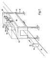
- the apparatus of the invention includes a support 10 carrying an enclosure 12 and adapted to straddle a conveyor 14 on which cans 16 are being conveyed, e.g. empty cans in transport to a filling and sealing system.
- a light source 22 which may be a diffused multiple tungsten lamp, fluorescent lamp or laser source such as a helium-neon laser providing a plane of light through a cylindrical lens.
- the cameras 18, 20 are supported vertically above the path of the moving cans to be tested, which path passes through the enclosure 12, so as to view the upper nominally round face 24 thereof which is illuminated by the light source 22.
- One camera is aligned with its scan direction on and along the locus of movement of the centre of the face 24; the other camera is aligned at right angles thereto, taking successive measurements normal to the direction of motion as the can passes underneath.
- an electronic control box 26 housing primary logic circuitry and microcomputer, with access via an electronics control panel 28.
- the enclosure 12 also has a removable inspection panel 30 to enable cans passing through the test station to be visually inspected, and also to enable insertion of test pieces for alignment and calibration purposes.
- the first camera 18 provides, for example, a measurement of the maximum width (diameter) of the can from edge to edge, and of the width of the edge rim at both the leading and trailing edges.
- the relative motion of the can as detected by this first camera is used to provide scan synchronisation for the second camera 20.
- the electronic control circuitry 26, later described, includes a timing clock to control camera operation and data processing, if desired accompanied by data read-out to a data logger.
- a line scan synchronising signal is provided to indicate the start of a new line.
- the camera video signals are digitised with respect to the set level of a discriminator, and the digitsed signals are processed and the measurement signals analysed by the computer.
- the source 22 is driven by a d.c. power supply (not shown) in order to achieve a constant and uniform illumination of the face of the can viewed by the cameras.
- an ejector mechanism (not shown) is controlled by a signal derived from the computer to reject cans not meeting set standards of shape and dimension which are pre-set in or programmed into the computer.
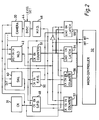
- control electronics include a clock 31 providing for generation of control signals within the CCD camera 20, which scans perpendicular to the line of the conveyor.
- a clock 31 providing for generation of control signals within the CCD camera 20, which scans perpendicular to the line of the conveyor.
- Generally analogous circuitry associated with the same microcomputer 32 may exist for the camera 18.
- the interface between the camera 20 and the computer 32 comprises, in addition to the clock 30, integrated circuit logic which will now be described.
- a start-new-line signal is generated either by an external control (e.g. another camera such as camera 18) or by the computer or again the camera may be free-running as a sub-multiple of the scan clock.
- the SNL generator 40 (or the control signals generator in the camera) set the new-line-detected latch (NLD) 42.
- the video signal from the camera 18 is converted to a digital signal in the discriminator (disc) 44 by comparison with a pre-set reference signal.
- the digitised signal is checked for missing or marginal pulses by the missing-pulse-detector (MPD) 46, and provides an enable signal indicating an edge or other feature of interest on the can.
- MPD missing-pulse-detector
- the leading edge of the MPD signal sets the start-pulse-detector latch (SPD) 48 and the trailing edge sets the end-pulse-detector latch (EPD) 50.
- the new-line-detector 42 set by the SNL 40 indicates the start of a new scan line and is reset by the EPD 50 at the end of the first detected edge.
- Counter 51 is reset to zero by the leading edge of the NLD 42 and thereafter counts the CCD camera diode scan position for that line.
- the contents of the counter are transferrd to latch 54 by the SPD latch 48 in conjunction with the NLD latch 42, thereby transferring the leading-edge coordinate of the can.
- the EPD latch 50 transfers successive trailing edge coordinates to latch 56 until, at the end of the line scan, latch 56 contains the coordinate of the far edge of the can.
- counters 57 and 58 contain the width of the first and last edges of the can detected. Both counters are enabled by the MPD 46 and count clock pulses while the MPD is active. Counter 57 counts the width of the leading edge while the NLD is active while counter 58 counts successive events when the NLD is reset, until the far edge width remains at the end of the scan line: each successive event in the line causes counter 58 to be reset by the SPD latch 48, although only the first and last events in the line are associated with useful data, inbetween events generally being spurious. In the event of a single edge being detected counter 58 will contain zero.
- Data is transferred to the microcomputer 32 under control of the NLD latch 42.
- NLD 42 When the NLD 42 resets, an interrupt indicates that data in the latch 54 and counter 57 are ready for transfer.
- an interrupt indicates that data in the latch 56 and counter 58 are ready for transfer.
- another interrupt indicates that data in the latch 56 and counter 58 are ready for transfer. In the event of a single edge being detected the only interrupt will be at the end of the scan-line; if the contents of latch 54 is zero no edge has been detected.
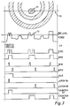
- the upper part of the illustration indicates a line scan 70 across a can top having a blemish 72 and the waveforms below indicate the resulting signals generated at the various logic circuit components above described with reference to Figure 2.
- Each waveform is marked to indicate the relevant component to which it relates.
- the measurement signals generated are:- a) the leading edge position in latch 54; b) the trailing edge position in latch 56; c) the width of rim at the leading edge in counter 57; d) the widths of blemish and rim at the trailing edge in counter 58.
- the computer 32 has stored therein reference values which set the limits for acceptance of the can with respect to distortions in shape and dimensional variations. If the measurement signals fail to meet the set limits, a can ejector device may be automatically operated under computer control.
- the preceding description relates to detection of simple ovality and dinting.
- the computer may be preset or programmed to process these signals cumulatively, and evaluate the shape and dimensions of the can more precisely as to errors in shape and dimensions, for example having regard to algorithms stored in its memory.
- errors in the edge rim of the can may be detected by a) comparing the width of the rim at the leading and trailing edges; b) comparing change in rim widths between successive parallel scans; c) integrating the rim width measurements over an arc around the can and effecting a comparison of the integrated values.
- a) comparing the width of the rim at the leading and trailing edges b) comparing change in rim widths between successive parallel scans
- ovality can be checked by:- a) comparing diameters in mutually perpendicular directions as above mentioned; b) checking that the maximum diameter is at the centre point of the perpendicular axis; c) checking that the median of the can, as measured on the appropriate axis, has a constant position.
- the above-described apparatus incorporating a suitably dedicated or programmed computer, is capable of:-
- a possible modification, in connection with features (g) above, is that of using two cameras scanning in parallel, one for detecting the beginning and one the end of a can rim.
Landscapes
- Physics & Mathematics (AREA)
- General Physics & Mathematics (AREA)
- Length Measuring Devices By Optical Means (AREA)
- Investigating Materials By The Use Of Optical Means Adapted For Particular Applications (AREA)
Claims (1)
- Appareil pour examiner la forme et/ou les dimensions d'objets, comprenant :- un moyen convoyeur (14) pour transporter les objets (16) suivant un trajet de déplacement ;- un poste de contrôle (12) situé sur ledit trajet de déplacement ;- un moyen à caméra électronique (18, 20) au poste de contrôle pour balayer les faces (24) des objets (16) qui lui sont présentés et pour fournir des signaux de sortie ;- un circuit électronique (26) pour la commande du fonctionnement de la caméra et pour traiter les signaux de sortie de la caméra pour fournir des signaux de mesure respectifs représentatifs de la forme et/ou des dimensions des objets (16) ; et- un moyen de comparaison (32) pour comparer les signaux de mesure respectifs avec des signaux de données de référence,
caractérisé en ce que ledit moyen à caméra (18, 20) comprend une première (18) et seconde (20) caméras linéaires balayant respectivement dans une direction du déplacement du convoyeur et dans une direction perpendiculaire à celle-ci, et en ce que ledit circuit électronique (26) est agencé de telle façon que les signaux de sortie de ladite première caméra (18), représentatifs du déplacement relatif des objets (16), fournissent un signal de synchronisation du balayage pour ladite seconde caméra (20).
Applications Claiming Priority (2)
| Application Number | Priority Date | Filing Date | Title |
|---|---|---|---|
| GB8512979A GB2175396B (en) | 1985-05-22 | 1985-05-22 | Apparatus for examining objects |
| GB8512979 | 1985-05-22 |
Publications (3)
| Publication Number | Publication Date |
|---|---|
| EP0206501A2 EP0206501A2 (fr) | 1986-12-30 |
| EP0206501A3 EP0206501A3 (en) | 1989-11-02 |
| EP0206501B1 true EP0206501B1 (fr) | 1992-07-22 |
Family
ID=10579534
Family Applications (1)
| Application Number | Title | Priority Date | Filing Date |
|---|---|---|---|
| EP86303693A Expired - Lifetime EP0206501B1 (fr) | 1985-05-22 | 1986-05-15 | Appareil pour le contrôle d'objets |
Country Status (6)
| Country | Link |
|---|---|
| US (1) | US4858156A (fr) |
| EP (1) | EP0206501B1 (fr) |
| JP (1) | JPS61271442A (fr) |
| DE (1) | DE3686100T2 (fr) |
| GB (1) | GB2175396B (fr) |
| IE (1) | IE58985B1 (fr) |
Families Citing this family (23)
| Publication number | Priority date | Publication date | Assignee | Title |
|---|---|---|---|---|
| JPS63265108A (ja) * | 1986-12-12 | 1988-11-01 | Toyo Seikan Kaisha Ltd | 缶の検査方法およびその装置 |
| EP0332376A3 (fr) * | 1988-03-07 | 1990-10-10 | Sentinel Vision Inc. | Appareil pour inspecter des jointures de boítes et analogues |
| DE4042465C2 (de) * | 1989-11-27 | 1995-03-02 | Gen Motors Corp | Kennform-Analysevorrichtung |
| US5164995A (en) * | 1989-11-27 | 1992-11-17 | General Motors Corporation | Signature analysis apparatus |
| WO1992003364A1 (fr) * | 1990-08-25 | 1992-03-05 | Intelligent Automation Systems, Inc. | Dispositif d'amenee de pieces reconfigurable programmable |
| US5142591A (en) * | 1990-09-21 | 1992-08-25 | Fmc Corporation | High resolution camera with hardware data compaction |
| GB2248931B (en) * | 1990-09-17 | 1995-01-04 | Fmc Corp | High resolution parts handling system |
| US5103304A (en) * | 1990-09-17 | 1992-04-07 | Fmc Corporation | High-resolution vision system for part inspection |
| US5233328A (en) * | 1990-09-17 | 1993-08-03 | Fmc Corporation | Method for processing compacted data |
| US5157486A (en) * | 1990-09-21 | 1992-10-20 | Fmc Corporation | High resolution camera sensor having a linear pixel array |
| WO1992017287A2 (fr) * | 1991-03-29 | 1992-10-15 | Csx Transportation, Inc. | Dispositif permettant de reconnaitre de maniere unique des containers de transport |
| US5369713A (en) * | 1992-07-09 | 1994-11-29 | Schwartz; Nira | Inspection method using area of interest (AOI) analysis |
| KR940005104A (ko) * | 1992-08-31 | 1994-03-16 | 김광호 | Ccd형 카메라의 스미어 제거방법 |
| US5387768A (en) * | 1993-09-27 | 1995-02-07 | Otis Elevator Company | Elevator passenger detector and door control system which masks portions of a hall image to determine motion and court passengers |
| US5286980A (en) * | 1992-10-30 | 1994-02-15 | Oms-Optical Measuring Systems | Product discrimination system and method therefor |
| US5410149A (en) * | 1993-07-14 | 1995-04-25 | Otis Elevator Company | Optical obstruction detector with light barriers having planes of light for controlling automatic doors |
| JPH08225279A (ja) * | 1995-02-23 | 1996-09-03 | Otis Elevator Co | エレベーターのドア安全装置 |
| US5892808A (en) * | 1996-06-28 | 1999-04-06 | Techne Systems, Inc. | Method and apparatus for feature detection in a workpiece |
| US6175415B1 (en) | 1997-02-19 | 2001-01-16 | United Technologies Corporation | Optical profile sensor |
| US6272437B1 (en) | 1998-04-17 | 2001-08-07 | Cae Inc. | Method and apparatus for improved inspection and classification of attributes of a workpiece |
| US6400833B1 (en) | 1998-06-19 | 2002-06-04 | Oms-Optical Measuring Systems | Method and apparatus for discrimination of product units from spread spectrum images of thin portions of product units |
| CN1606758A (zh) | 2000-08-31 | 2005-04-13 | 雷泰克公司 | 传感器和成像系统 |
| US7321699B2 (en) | 2002-09-06 | 2008-01-22 | Rytec Corporation | Signal intensity range transformation apparatus and method |
Family Cites Families (21)
| Publication number | Priority date | Publication date | Assignee | Title |
|---|---|---|---|---|
| GB1048585A (en) * | 1962-07-20 | 1966-11-16 | North Atlantic Res Products Lt | Apparatus for the automatic dimensional inspection of an object |
| US3389789A (en) * | 1965-12-10 | 1968-06-25 | Moore Vue Inc | Detecting and sorting means for sheets having flaws |
| GB1213983A (en) * | 1967-02-24 | 1970-11-25 | Raleigh Industries Ltd | A method of testing components and apparatus therefor |
| GB1238310A (fr) * | 1967-09-11 | 1971-07-07 | ||
| US3812376A (en) * | 1972-02-18 | 1974-05-21 | Agency Ind Science Techn | Device for controlling dimensional accuracy during machining of a cylindrical workpiece |
| SE7308776L (fr) * | 1973-06-21 | 1974-12-23 | Platmanufaktur Ab | |
| US4115803A (en) * | 1975-05-23 | 1978-09-19 | Bausch & Lomb Incorporated | Image analysis measurement apparatus and methods |
| JPS55110905A (en) * | 1979-02-20 | 1980-08-27 | Hajime Sangyo Kk | Defect detecting device |
| JPS55132904A (en) * | 1979-04-05 | 1980-10-16 | Fuji Electric Co Ltd | Shape inspection system |
| DE2916361A1 (de) * | 1979-04-23 | 1980-11-06 | Siemens Ag | Verfahren und anordnung zum pruefen des randes von durchsichtigen gefaessen |
| GB2111213A (en) * | 1981-12-09 | 1983-06-29 | Neuss Schraubenwerk | Method and apparatus for sorting screws |
| EP0085124B1 (fr) * | 1982-01-30 | 1987-11-04 | NHK SPRING CO., Ltd. | Dispositif pour contrôler des vis |
| US4493105A (en) * | 1982-03-31 | 1985-01-08 | General Electric Company | Method and apparatus for visual image processing |
| US4549205A (en) * | 1982-05-10 | 1985-10-22 | Takeda Chemical Industries, Ltd. | Ampoule inspecting method |
| JPS5987081A (ja) * | 1982-11-09 | 1984-05-19 | 池上通信機株式会社 | 外観品位検査方式 |
| US4608709A (en) * | 1983-03-08 | 1986-08-26 | Owens-Illinois, Inc. | Method and apparatus for gauging containers |
| JPS59182301A (ja) * | 1983-03-31 | 1984-10-17 | Hokuyo Automatic Co | ワ−ク外形寸法測定装置 |
| US4581632A (en) * | 1983-05-27 | 1986-04-08 | Key Technology, Inc. | Optical inspection apparatus for moving articles |
| EP0149457B1 (fr) * | 1984-01-13 | 1993-03-31 | Kabushiki Kaisha Komatsu Seisakusho | Méthode d'identification de lignes de contour |
| JPS61193009A (ja) * | 1985-02-22 | 1986-08-27 | Toyo Glass Kk | 容器の開口天面欠陥検査方法 |
| JPS6269154A (ja) * | 1985-09-21 | 1987-03-30 | Hajime Sangyo Kk | 壜口欠陥検査装置 |
-
1985
- 1985-05-22 GB GB8512979A patent/GB2175396B/en not_active Expired
-
1986
- 1986-04-22 US US06/854,604 patent/US4858156A/en not_active Expired - Lifetime
- 1986-05-15 EP EP86303693A patent/EP0206501B1/fr not_active Expired - Lifetime
- 1986-05-15 DE DE8686303693T patent/DE3686100T2/de not_active Expired - Fee Related
- 1986-05-21 IE IE134886A patent/IE58985B1/en not_active IP Right Cessation
- 1986-05-22 JP JP61118975A patent/JPS61271442A/ja active Pending
Non-Patent Citations (1)
| Title |
|---|
| G. Seger, U. Scheiding und H. Schmalfuss: "Qualitätskontrolle durch automatische Sichtprüfung" in "messen + prüfen/automatik" Juni 1984, S. 312-316 * |
Also Published As
| Publication number | Publication date |
|---|---|
| DE3686100T2 (de) | 1993-01-07 |
| DE3686100D1 (de) | 1992-08-27 |
| EP0206501A3 (en) | 1989-11-02 |
| GB2175396B (en) | 1989-06-28 |
| IE58985B1 (en) | 1993-12-15 |
| JPS61271442A (ja) | 1986-12-01 |
| US4858156A (en) | 1989-08-15 |
| GB2175396A (en) | 1986-11-26 |
| IE861348L (en) | 1986-11-22 |
| GB8512979D0 (en) | 1985-06-26 |
| EP0206501A2 (fr) | 1986-12-30 |
Similar Documents
| Publication | Publication Date | Title |
|---|---|---|
| EP0206501B1 (fr) | Appareil pour le contrôle d'objets | |
| US4136930A (en) | Method and apparatus for detecting foreign particles in full beverage containers | |
| US4972494A (en) | Package inspection system | |
| US4446481A (en) | Automatic product inspection system | |
| US4488648A (en) | Flaw detector | |
| US5917602A (en) | System and method for image acquisition for inspection of articles on a moving conveyor | |
| US5095204A (en) | Machine vision inspection system and method for transparent containers | |
| US5646724A (en) | Threaded parts inspection device | |
| US4584469A (en) | Optical detection of radial reflective defects | |
| EP0330495A2 (fr) | Système d'inspection d'emballages | |
| US4958223A (en) | Inspection of container finish | |
| US4553217A (en) | Glassware gauging system | |
| US4608709A (en) | Method and apparatus for gauging containers | |
| JPH01199139A (ja) | 対象物の透明度のコントラストにより対象物を検査する方法に用いる回路 | |
| US4165939A (en) | Apparatus for inspection and dimensional measurement by sequential reading | |
| EP3605010A1 (fr) | Procédé et dispositif de détection de défauts dans la fermeture de flacons encapsulés | |
| JP4361156B2 (ja) | 物品の外観検査装置 | |
| GB2094781A (en) | Detecting fused glass particles in glass containers | |
| CA1293051C (fr) | Appareil servant a l'examen d'objets | |
| KR101358112B1 (ko) | 대상물의 복수 부분을 검사하기 위한 비전 검사 장치 | |
| PH26987A (en) | Inspection of container finish | |
| GB2093987A (en) | Photo-electric determination of dimensions and surface quality | |
| JP3592615B2 (ja) | 物品の内面検査装置 | |
| EP0747854A2 (fr) | Méthode et appareil pour détecter des récipients sur un convoyeur | |
| JP3822789B2 (ja) | 部品寸法測定装置 |
Legal Events
| Date | Code | Title | Description |
|---|---|---|---|
| PUAI | Public reference made under article 153(3) epc to a published international application that has entered the european phase |
Free format text: ORIGINAL CODE: 0009012 |
|
| AK | Designated contracting states |
Kind code of ref document: A2 Designated state(s): BE DE FR IT NL |
|
| RAP1 | Party data changed (applicant data changed or rights of an application transferred) |
Owner name: SOUDRONIC AG |
|
| PUAL | Search report despatched |
Free format text: ORIGINAL CODE: 0009013 |
|
| AK | Designated contracting states |
Kind code of ref document: A3 Designated state(s): BE DE FR IT NL |
|
| 17P | Request for examination filed |
Effective date: 19890929 |
|
| 17Q | First examination report despatched |
Effective date: 19910102 |
|
| GRAA | (expected) grant |
Free format text: ORIGINAL CODE: 0009210 |
|
| AK | Designated contracting states |
Kind code of ref document: B1 Designated state(s): BE DE FR IT NL |
|
| REF | Corresponds to: |
Ref document number: 3686100 Country of ref document: DE Date of ref document: 19920827 |
|
| ET | Fr: translation filed | ||
| ITF | It: translation for a ep patent filed | ||
| PLBE | No opposition filed within time limit |
Free format text: ORIGINAL CODE: 0009261 |
|
| STAA | Information on the status of an ep patent application or granted ep patent |
Free format text: STATUS: NO OPPOSITION FILED WITHIN TIME LIMIT |
|
| 26N | No opposition filed | ||
| PGFP | Annual fee paid to national office [announced via postgrant information from national office to epo] |
Ref country code: BE Payment date: 19940315 Year of fee payment: 9 |
|
| PGFP | Annual fee paid to national office [announced via postgrant information from national office to epo] |
Ref country code: FR Payment date: 19940420 Year of fee payment: 9 |
|
| PG25 | Lapsed in a contracting state [announced via postgrant information from national office to epo] |
Ref country code: BE Effective date: 19950531 |
|
| BERE | Be: lapsed |
Owner name: SOUDRONIC A.G. Effective date: 19950531 |
|
| PG25 | Lapsed in a contracting state [announced via postgrant information from national office to epo] |
Ref country code: FR Effective date: 19960229 |
|
| REG | Reference to a national code |
Ref country code: FR Ref legal event code: ST |
|
| REG | Reference to a national code |
Ref country code: FR Ref legal event code: ST |
|
| PGFP | Annual fee paid to national office [announced via postgrant information from national office to epo] |
Ref country code: DE Payment date: 20030512 Year of fee payment: 18 |
|
| PGFP | Annual fee paid to national office [announced via postgrant information from national office to epo] |
Ref country code: NL Payment date: 20030523 Year of fee payment: 18 |
|
| PG25 | Lapsed in a contracting state [announced via postgrant information from national office to epo] |
Ref country code: NL Free format text: LAPSE BECAUSE OF NON-PAYMENT OF DUE FEES Effective date: 20041201 Ref country code: DE Free format text: LAPSE BECAUSE OF NON-PAYMENT OF DUE FEES Effective date: 20041201 |
|
| NLV4 | Nl: lapsed or anulled due to non-payment of the annual fee |
Effective date: 20041201 |
|
| PG25 | Lapsed in a contracting state [announced via postgrant information from national office to epo] |
Ref country code: IT Free format text: LAPSE BECAUSE OF NON-PAYMENT OF DUE FEES;WARNING: LAPSES OF ITALIAN PATENTS WITH EFFECTIVE DATE BEFORE 2007 MAY HAVE OCCURRED AT ANY TIME BEFORE 2007. THE CORRECT EFFECTIVE DATE MAY BE DIFFERENT FROM THE ONE RECORDED. Effective date: 20050515 |