EP0206458A2 - Vibrationsempfindlicher Transduktor - Google Patents
Vibrationsempfindlicher Transduktor Download PDFInfo
- Publication number
- EP0206458A2 EP0206458A2 EP86302727A EP86302727A EP0206458A2 EP 0206458 A2 EP0206458 A2 EP 0206458A2 EP 86302727 A EP86302727 A EP 86302727A EP 86302727 A EP86302727 A EP 86302727A EP 0206458 A2 EP0206458 A2 EP 0206458A2
- Authority
- EP
- European Patent Office
- Prior art keywords
- type transducer
- transducer according
- cable type
- electrical conductor
- cable
- Prior art date
- Legal status (The legal status is an assumption and is not a legal conclusion. Google has not performed a legal analysis and makes no representation as to the accuracy of the status listed.)
- Granted
Links
Images

Classifications
-
- G—PHYSICS
- G08—SIGNALLING
- G08B—SIGNALLING OR CALLING SYSTEMS; ORDER TELEGRAPHS; ALARM SYSTEMS
- G08B13/00—Burglar, theft or intruder alarms
- G08B13/02—Mechanical actuation
- G08B13/12—Mechanical actuation by the breaking or disturbance of stretched cords or wires
- G08B13/122—Mechanical actuation by the breaking or disturbance of stretched cords or wires for a perimeter fence
-
- G—PHYSICS
- G01—MEASURING; TESTING
- G01H—MEASUREMENT OF MECHANICAL VIBRATIONS OR ULTRASONIC, SONIC OR INFRASONIC WAVES
- G01H11/00—Measuring mechanical vibrations or ultrasonic, sonic or infrasonic waves by detecting changes in electric or magnetic properties
- G01H11/02—Measuring mechanical vibrations or ultrasonic, sonic or infrasonic waves by detecting changes in electric or magnetic properties by magnetic means, e.g. reluctance
-
- G—PHYSICS
- G01—MEASURING; TESTING
- G01V—GEOPHYSICS; GRAVITATIONAL MEASUREMENTS; DETECTING MASSES OR OBJECTS; TAGS
- G01V1/00—Seismology; Seismic or acoustic prospecting or detecting
- G01V1/16—Receiving elements for seismic signals; Arrangements or adaptations of receiving elements
- G01V1/20—Arrangements of receiving elements, e.g. geophone pattern
- G01V1/201—Constructional details of seismic cables, e.g. streamers
- G01V1/208—Constructional details of seismic cables, e.g. streamers having a continuous structure
Definitions
- the present invention relates to a linear vibration-sensitive transducer designed primarily to be attached to perimeter fences or other structures although it may well find applications in other fields not directly related to the security industry.
- the transducer operates by producing electrical signals in response to mechanical vibrations impinging on the outer surface of the device. When the signals thus produced are electronically processed, it is possible to determine the nature of the disturbance causing the signals, and hence give warning of impending malicious acts.
- buffer circuitry must be interposed between the sensor and the interconnecting cable so that the higher frequency components of the signal are not attenuated by the cable capacitance.
- this circuitry must be physically adjacent to the sensor and may be exposed to extremes of climatic conditions thus reducing system reliability.
- the buffer circuitry requires a power source which, in most cases, will necessitate an additional pair of conductors to be routed to the interface box. This additional cabling involves a significant increase in the installed cost and is hence undesirable. High source impedances also pre-empt the realisation of a truly low-noise, high-gain system, since a pre-requisite of a low-noise system is a low source impedance.
- the degree of sensitivity is related to the level of electrical stress which can be applied to the dielectric during the sensitisation process. Since it is impossible to guarantee 100% uniformity of cable dimensions during manufacture, it follows that the maximum stress which can be applied to the cable must be modified to prevent breakdown at the weakest point in the cable. This means that all other points along the length of the cable will be less sensitive than the weakest section(s) as well as exhibiting variations of sensitivity at other manufacturing discontinuities.
- the sensor described in the following text operates on an entirely different principle to those outlined earlier.
- the co-axial types of sensor involve the movement of conductors in an electric field
- this sensor relies on the movement of conductors in a magnetic field.
- the mechanical movement of a conductor in a magnetic field will result in the generation of an EMF across the ends of the conductor.
- a conductor is arranged in such a way as to allow it to vibrate within a magnetic field in response to externally generated mechanical vibrations impinging on the outer sheath of the sensor. Since it is now possible to obtain flexible magnetic materials, it is possible to construct a vibration sensor based on this principle and offering the advantages of the earlier types of cable sensors.
- a cable type transducer for producing electrical signals in response to a mechanical vibration or impulse comprising an elongate structure comprising magnetic flux generating means and an electrical conductor movable, in response to mechanical disturbance of the cable, in the magnetic field generated by the flux generating means thereby to produce said signals.
- the flux generating means comprises an elongate portion of flexible magnetised material.
- This can be in the form of a tape with the electrical conductor or conductors, for example, along one edge (where there is one) or two electrical conductors (where there are two), for example one on either edge.
- the conductors may be made of very fine wire loosely fitting into a small bore tube attached to, or integral with, the flux generating means.
- the conductor or conductors may be arranged so as to be non-inductive with respect to an external applied field; this may for example be achieved by wiring them in a circuit with additional conductors which are fixed so as not to vibrate in the magnetic field and thereby not to have EMFs induced in them. Furthermore, they may be arranged so as to produce a balanced output relative to a 'centre tap'; the centre tap may be provided by one or more of the fixed conductors just mentioned, or, if the magnetised core is conductive, by the core.
- a wire loosely fitting within its sleeve may be arranged along the core in a "twisted pair" configuration with a conductor which is not movable relative to the core, e.g. a conventional insulated wire fixed to the core.
- a conductor which is not movable relative to the core
- the use of a twisted pair gives high inherent noise immunity, while having one wire fixed avoids signal cancellation as compared with having two loosely mounted wires.
- the transducer may be in the form of a cable comprising a generally circular cross-section magnetized core having slots in its surface which house the electrical conductors.
- the core may be formed in one piece or from two or more complementary similarly-shaped parts, e.g. two parts having generally semi-circular cross-section and having recesses in its surface which, when the two halves are assembled, define the longitudinally extending slots for the conductors.
- the slots for the return conductors may be of the same size or preferably slightly smaller than the diameter of the conductor, while the slots for the active conductor are larger than the diameter of the conductor.
- the assembly of core and conductors is preferably sheathed with an outer jacket material serves to protect the cable and may also serve to prevent the active conductors being displaced from their slots.
- An electrostatic shield of foil tape may be wound around the core and conductors before sheathing with the outer jacket.
- an extruded plastics section may be pressed into the slots before the jacket is added.
- the construction of the cable in an overall circular cross-section has the advantages as compared with a tape that various standard accessories and components (e.g. grommets and glands) can be used with it, that manufacture is more straightforward and that a more intense field, i within which the conductor(s) move can, be generated.
- various standard accessories and components e.g. grommets and glands
- the invention further provides a monitoring apparatus, for security-or hazard-or other state-monitoring purposes which, in use, is coupled to the transducer and includes the circuitry responsive to an EMF induced in a the transducer to produce an electrical signal indicative of said state; the transducer may be one per se embodying the invention.
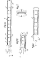
- Figure 1 shows the general arrangement of conductors in a first embodiment of the invention and their physical placement in relation to core 2 of the magnetic material.
- the magnetic core 2, which is the central component of the assembly, comprises a flexible strip of metallic material which is permanently magnetised by subjecting it to a powerful external magnetic field; alternatively the core 2 could be made of a plastics material, preferably electrically conductive as it is advantageous for the core to be connected to the system earth of the monitor to which the transducer 1 is connected.
- the direction of polarisation of the field is at right-angles to the length of the strip and the sense of the field is the same throughout the length of the strip.
- the strip is suitably only of the order of 0.05mm thick, while the strip width is in the region of 6mm.
- Figure 2 shows the distribution of the magnetic flux as would be seen looking on the end of a section of the strip.
- a respective conductive wire 3a, 3b which is loosely fitted in a respective small bore tube or sheath 4a, 4b secured to, or integral with, the core 1.
- the wires 3a, 3b are thus adjacent to the respective poles of the core 1. Any vibration transmitted through the sheath of the assembly will cause the wire to vibrate in sympathy and in doing so will induce an E.M.F. in the wire as a result of its movement within the magnetic field.
- the signal output is taken from the left-hand ends of conductors 3a and 5a and is balanced with respect to a centre tap CT provided by the connection between the left-hand ends of conductors 3b and 5b. It will be seen that at the remote, righthand end, the conductors cross over, conductor 5a being connected to conductor 3b and conductor 5b to conductor 3a. All the conductors may be enamel coated or otherwise insulated.
- Figure lb is intended to facilitate an appreciation of the operation of the embodiment of Figure 1A and shows the input impedance Z of the monitoring circuit.
- the monitoring circuit can include any suitable type of analogue and digital circuitry or both for suitably monitoring the output of the transducer and producing one or more signal outputs indicative of the state which it is desired to monitor.
- the circuitry may include signal processing circuitry for monitoring one or more characterstics of the transducer output e.g. spectral content, amplitude or duration, which depends on the vibration or movement which it is desired to detect.
- the overall arrangement of the conductors shown in I Figure 1A is chosen to maximise the signal level caused by mechanical vibration while minimising the signals induced by external electro-magnetic fields. This is achieved by arranging the loop formed by the conductors to be non-inductive as far as external electro-magnetic fields are concerned.
- return conductors 5a, 5b i.e.- not the vibrating conductors secured relative to the core 1 via the extruded sheathing material run along a path which follows the active conductor as closely as possible so that the overall conductor assembly appears to be a bifilar-wound I loop i.e. two loops of opposite senses, which will tend to cancel the effect of externally induced magnetic fields.
- Figure 3 shows this less advantageous arrangement where there are just the two sheathed conductors 3a and 4a attached to opposite sides of the core 2.
- Figure 4 illustrates a variation on the arrangement shown in Figure 3.
- a metallic magnetic strip 2 is used as the return conductor instead of having separate conductors such as 5a and 5b in Figures 1A and 1B so that the currents induced in the active conductors are now in-phase, thus increasing the sensitivity of the sensor.
- This arrangement however, in common with that of Figure 3, may be prone to externally induced electro-magnetic interference.
- Figure 5 shows a variation on the arrangement of Figure 1.
- the active conductor/tube assemblies 3a, 4a, 3b, 4b are mounted on the face of the magnetic strip 2 adjacent to the edges.
- the conductors and magnetic strip are "locked” in place relative to each other, it is possible to "fold” the assembly in half as shown in Figure 6. If, as shown, the "active" conductors 3a,3b are “sandwiched” together between the folded magnetic strip 2, they are now subject to a more intense magnetic field as a result of the reduction in the air-gap between the poles of the magnet.
- the magnetic strip now appears to be similar to the familiar "horseshoe" type of magnet.
- Figures 7a to 7c show a further embodiment of the invention which is intended to reduce or eliminate these disadvantages.
- the conductors 3a, 3b have been replaced by an element A comprising a conductor 3, again loosely fitting within its sheath 4 and so movable relative to the magnetic core 2, arranged in a "twisted pair" with, and connected at the remote end by a conductor link 8 to an element B comprising a wire 6 which is a conventional wire with a conducting core 7 and a close-fitting sheath 9 and so the conducting core 7 is unable to move relative to the magnetic core 2 to the same degree as is the wire 3.
- the twisted pair of conductors are held in place, in contact with the surface of the metallic strip by the outer jacket of the cable.
- wires in a twisted pair configuration overcomes the first problem of induced interference as it has inherent immunity to external electromagnetic interference.
- the use of the wire 6 is to overcome the problem of signal cancellation, since it will not vibrate within the magnetic field of the core 2 and will therefore prevent signal cancellation occurring.
- both conductors in this arrangement will be identical in respect of factors determining resistance material, cross-sectional area, construction, temperature coefficient etc.
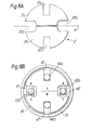
- Figures 8a and 8b show a second embodiment of the invention where the transducer is in the form of a cable rather than a tape.
- the core 2 is constructed from two identically shaped parts 2a and 2b of magnetic material. Each part is generally of semi-circular cross-section and has formed in its surface a rectangular recess 12a or 12b which defines a longitudinally extending slot and two longitudinally extending, oppositely disposed radiused rebates 10a and lOb. When assembled as shown the two parts form a core having two pairs of longitudinally extending slots 10 and 12 symmetrically disposed about the plane 11.
- the radiused rebates are of such a size that the pair of slots 10 they define in the assembled core is wider than the pair of rectangular slots 12.
- the two parts 2a and 2b of the core are magnetized to give the pole configurations shown in Figure 8B and designated by "N" and "S".
- Such a pole configuration has the advantage that the two parts of the core tend to attract each other which assists manufacture.
- the transducer is constructed as shown in Figure 8b.
- the conductors 13a, 13b, 14a and 14b are all the same with return conductors 14a, 14b in slots 12 and active conductors 13a, 13b in slots 10.
- the conductors have such a diameter that the return conductors 14a, 14b are held firmly in fixed position in the slots 12, but the active conductors 13a, 13b are free to move in slots 10 in response to mechanical vibration of the cable and thereby generate the electrical signals.
- the core and conductors are sheathed in an outer jacket 15 which is of plastics material extruded onto the cable.
- the outer jacket 15 serves the dual function of protecting the cable and preventing the active conductors 13a, 13b from coming out of the slots 10.
- a layer of foil tape 16 may be wound around the core and conductors before the outer jacket 15 is put on. This provides an electrostatic screen and also prevents ingress of the jacket material into the slot. An alternative way of preventing this ingress is to press an extruded plastics section into the slots before putting on the jacket.
- the conductors may be connected in the similar configurations to those described in connection with the first embodiment to provide a non-inductive loop on a balanced or differential output.
- An alternative way of allowing the active conductors to move while holding the return conductors still is to make all the longitudinally extending slots equal width and use return conductors of a larger diameter than the active conductors.
Landscapes
- Physics & Mathematics (AREA)
- General Physics & Mathematics (AREA)
- Life Sciences & Earth Sciences (AREA)
- Environmental & Geological Engineering (AREA)
- Geology (AREA)
- Remote Sensing (AREA)
- General Life Sciences & Earth Sciences (AREA)
- Engineering & Computer Science (AREA)
- Geophysics (AREA)
- Acoustics & Sound (AREA)
- Measurement Of Mechanical Vibrations Or Ultrasonic Waves (AREA)
- Electrophonic Musical Instruments (AREA)
- Geophysics And Detection Of Objects (AREA)
- Measuring Fluid Pressure (AREA)
- Surgical Instruments (AREA)
- Photoreceptors In Electrophotography (AREA)
- Discharging, Photosensitive Material Shape In Electrophotography (AREA)
- Burglar Alarm Systems (AREA)
Priority Applications (1)
| Application Number | Priority Date | Filing Date | Title |
|---|---|---|---|
| AT86302727T ATE77879T1 (de) | 1985-04-17 | 1986-04-11 | Vibrationsempfindlicher transduktor. |
Applications Claiming Priority (4)
| Application Number | Priority Date | Filing Date | Title |
|---|---|---|---|
| GB8509815 | 1985-04-17 | ||
| GB8509815 | 1985-04-17 | ||
| GB8531050 | 1985-12-17 | ||
| GB858531050A GB8531050D0 (en) | 1985-04-17 | 1985-12-17 | Vibration transducer |
Publications (3)
| Publication Number | Publication Date |
|---|---|
| EP0206458A2 true EP0206458A2 (de) | 1986-12-30 |
| EP0206458A3 EP0206458A3 (en) | 1988-09-21 |
| EP0206458B1 EP0206458B1 (de) | 1992-07-01 |
Family
ID=26289136
Family Applications (1)
| Application Number | Title | Priority Date | Filing Date |
|---|---|---|---|
| EP86302727A Expired - Lifetime EP0206458B1 (de) | 1985-04-17 | 1986-04-11 | Vibrationsempfindlicher Transduktor |
Country Status (6)
| Country | Link |
|---|---|
| US (1) | US4760295A (de) |
| EP (1) | EP0206458B1 (de) |
| AT (1) | ATE77879T1 (de) |
| AU (1) | AU591894B2 (de) |
| DE (1) | DE3685859T2 (de) |
| GB (1) | GB2175771B (de) |
Cited By (1)
| Publication number | Priority date | Publication date | Assignee | Title |
|---|---|---|---|---|
| DE29613790U1 (de) * | 1996-08-09 | 1996-09-26 | Festo Kg | Mikroschalter |
Families Citing this family (13)
| Publication number | Priority date | Publication date | Assignee | Title |
|---|---|---|---|---|
| DE3629904A1 (de) * | 1986-09-03 | 1988-03-17 | Marcel Frans Christi Schemmann | Vorrichtung mit mechanisch schwingenden bereichen insbesondere zur erzeugung akustischer signale |
| US4906975A (en) * | 1988-11-18 | 1990-03-06 | Mrm Security Systems, Inc. | Vibration responsive intrusion detection barrier |
| US5448222A (en) * | 1993-12-09 | 1995-09-05 | Southwest Microwave, Inc. | Coupled transmission line sensor cable and method |
| US5446446A (en) * | 1993-12-09 | 1995-08-29 | Southwest Microwave, Inc. | Differential, multiple cell reflex cable intrusion detection system and method |
| WO2000079500A1 (en) * | 1999-06-21 | 2000-12-28 | Telenetics Corporation | Remote meter monitoring system and method |
| WO2005013223A1 (en) * | 2003-08-01 | 2005-02-10 | Senstar-Stellar Corporation | Cable guided intrusion detection sensor, system and method |
| EP2235706A4 (de) * | 2008-01-04 | 2012-04-04 | Rae-Woong Park | System zur verhinderung von verbrechen und katastrophen |
| US20100109840A1 (en) * | 2008-10-31 | 2010-05-06 | Robert Schilling | Radio Frequency Identification Read Antenna |
| GB0922044D0 (en) * | 2009-12-17 | 2010-02-03 | Geoquip Ltd | Improvements in or relating to sensing apparatus |
| GB201007730D0 (en) * | 2010-05-08 | 2010-06-23 | Geoquip Ltd | Sensing apparatus |
| GB2490179B (en) | 2011-06-01 | 2013-04-24 | Detection Technologies Ltd | Security system, controller for a security system, transducing cable for a security system and method for detecting a disturbance and determining its location |
| WO2017193201A1 (en) | 2016-05-12 | 2017-11-16 | Fiber Sensys, Inc. | Mimo cable guided intrusion detection sensor |
| GB2551391A (en) * | 2016-06-17 | 2017-12-20 | Crh Fencing & Security Group (Uk) Ltd | An apparatus and system for sensing movement |
Citations (3)
| Publication number | Priority date | Publication date | Assignee | Title |
|---|---|---|---|---|
| US3659257A (en) * | 1968-11-04 | 1972-04-25 | Woods Hole Oceanographic Inst | Continuous magnetic line hydrophone |
| US3846790A (en) * | 1973-06-08 | 1974-11-05 | Honeywell Inc | Intrusion detection systems |
| GB2063537A (en) * | 1979-11-13 | 1981-06-03 | Honeywell Inc | Sensor for use with intrusion detection circuitry |
Family Cites Families (41)
| Publication number | Priority date | Publication date | Assignee | Title |
|---|---|---|---|---|
| US2304738A (en) * | 1939-06-29 | 1942-12-08 | Socony Vacuum Oil Co Inc | Seismograph |
| US2807793A (en) * | 1954-10-01 | 1957-09-24 | Exxon Research Engineering Co | Continuous reelable geophone |
| US3353040A (en) * | 1965-07-20 | 1967-11-14 | Frank R Abbott | Electrodynamic transducer |
| US3375490A (en) * | 1965-11-17 | 1968-03-26 | Texaco Inc | Flexible cablelike transducer |
| US3475751A (en) * | 1966-07-07 | 1969-10-28 | Executone Inf Sys Inc | Remote sound monitoring and control system |
| GB1230373A (de) * | 1967-01-03 | 1971-04-28 | ||
| CH485207A (fr) * | 1967-11-30 | 1970-01-31 | Ebauches Sa | Transducteur courant-force à action linéaire |
| GB1278249A (en) * | 1968-12-10 | 1972-06-21 | Marconi Co Ltd | Improvements in or relating to vibration detectors |
| US3651283A (en) * | 1968-12-18 | 1972-03-21 | Audio Arts Inc | Loudspeaker having elongated rectangular moving coil |
| US3579220A (en) * | 1969-03-28 | 1971-05-18 | Automatic Sprinkler Corp | Alarm system |
| US3610973A (en) * | 1970-01-08 | 1971-10-05 | Westinghouse Electric Corp | Vibration pickup device |
| US3674946A (en) * | 1970-12-23 | 1972-07-04 | Magnepan Inc | Electromagnetic transducer |
| NL7101185A (de) * | 1971-01-29 | 1972-08-01 | ||
| FR2133079A5 (de) * | 1971-04-07 | 1972-11-24 | Francais Detection Eletr | |
| GB1350465A (en) * | 1971-05-07 | 1974-04-18 | Rank Organisation Ltd | Transducer |
| US3703681A (en) * | 1971-05-14 | 1972-11-21 | Honeywell Inc | Thin film line sensor for measuring magnetic fields, pressure, vibration or physical displacement |
| US3689875A (en) * | 1971-05-27 | 1972-09-05 | Exxon Production Research Co | Flexible geophone |
| US3836899A (en) * | 1973-09-04 | 1974-09-17 | Gte Sylvania Inc | Intrusion detection and locating system |
| US4004268A (en) * | 1975-02-06 | 1977-01-18 | Teledyne Industries, Inc. | In-line stress/strain detector |
| US4099168A (en) * | 1975-11-06 | 1978-07-04 | Magnum Products, Inc. | Intrusion alarm and emergency illumination apparatus and method |
| AT350649B (de) * | 1977-05-26 | 1979-06-11 | Akg Akustische Kino Geraete | Mikrophon |
| US4259550A (en) * | 1978-04-15 | 1981-03-31 | Yoshiro Nakamatsu | Acoustic device with floating vibrating means |
| US4241338A (en) * | 1978-05-15 | 1980-12-23 | Ernst Spirig | Ambient noise intruder alarm |
| GB2020872B (en) * | 1978-05-15 | 1982-10-13 | Spirig Ernst | Ambient noise intruder alarm |
| GB2037535B (en) * | 1978-12-14 | 1983-01-12 | Rank Organisation Ltd | Moving coil transducers |
| DE2902545C2 (de) * | 1979-01-24 | 1985-04-04 | Akzo Gmbh, 5600 Wuppertal | Faden mit Leitschichten |
| US4307387A (en) * | 1979-02-23 | 1981-12-22 | Elliott Brothers (London) Limited | Vibration-responsive intruder alarm system |
| NL7908447A (nl) * | 1979-11-20 | 1981-06-16 | Philips Nv | Magneetsysteem voor een electroakoestische omzetter. |
| FR2471113A1 (fr) * | 1979-12-05 | 1981-06-12 | Audax | Membrane notamment pour transducteur electro-acoustique |
| GB2072458A (en) * | 1980-03-03 | 1981-09-30 | Tape Developments Ltd C | Electroacoustic transducers |
| US4319096A (en) * | 1980-03-13 | 1982-03-09 | Winey James M | Line radiator ribbon loudspeaker |
| NL8001592A (nl) * | 1980-03-18 | 1981-10-16 | Philips Nv | Mfb systeem met een overnamenetwerk. |
| JPS5717027A (en) * | 1980-07-03 | 1982-01-28 | Hitachi Ltd | Vibration reducing device of electric machinery |
| EP0057982B1 (de) * | 1981-02-06 | 1985-12-11 | EMI Limited | Sensor für Druckwellen |
| US4398972A (en) * | 1981-05-11 | 1983-08-16 | Bell Telephone Laboratories, Incorporated | Ferritic Fe-Ni magnetic alloys |
| FR2523339A1 (fr) * | 1982-03-12 | 1983-09-16 | Guglielmetti Vg Electro | Dispositif de detection a capteur volumetrique a infra-sons et procede de detection par infra-sons |
| US4523185A (en) * | 1982-03-15 | 1985-06-11 | Albert Roth | Zoned intrusion display with series-connected sensors |
| ATE26033T1 (de) * | 1982-05-06 | 1987-04-15 | Nat Technical Systems | Ueberwachung des auftretens menschlicher aktivitaet in einer umgebung. |
| GB2123651B (en) * | 1982-06-29 | 1986-08-06 | Stanley Kelly | Transducers |
| EP0113732A4 (de) * | 1982-07-19 | 1986-02-13 | Anthony Bernard Clarke | Elektromagnetisch-akustischer umwandler. |
| NL8300671A (nl) * | 1983-02-23 | 1984-09-17 | Philips Nv | Automatisch egalisatiesysteem met dtf of fft. |
-
1986
- 1986-04-11 GB GB08608886A patent/GB2175771B/en not_active Expired
- 1986-04-11 AT AT86302727T patent/ATE77879T1/de not_active IP Right Cessation
- 1986-04-11 DE DE8686302727T patent/DE3685859T2/de not_active Expired - Lifetime
- 1986-04-11 EP EP86302727A patent/EP0206458B1/de not_active Expired - Lifetime
- 1986-04-15 US US06/852,344 patent/US4760295A/en not_active Expired - Lifetime
- 1986-04-16 AU AU56152/86A patent/AU591894B2/en not_active Expired
Patent Citations (3)
| Publication number | Priority date | Publication date | Assignee | Title |
|---|---|---|---|---|
| US3659257A (en) * | 1968-11-04 | 1972-04-25 | Woods Hole Oceanographic Inst | Continuous magnetic line hydrophone |
| US3846790A (en) * | 1973-06-08 | 1974-11-05 | Honeywell Inc | Intrusion detection systems |
| GB2063537A (en) * | 1979-11-13 | 1981-06-03 | Honeywell Inc | Sensor for use with intrusion detection circuitry |
Cited By (1)
| Publication number | Priority date | Publication date | Assignee | Title |
|---|---|---|---|---|
| DE29613790U1 (de) * | 1996-08-09 | 1996-09-26 | Festo Kg | Mikroschalter |
Also Published As
| Publication number | Publication date |
|---|---|
| GB2175771B (en) | 1989-01-11 |
| GB2175771A (en) | 1986-12-03 |
| AU591894B2 (en) | 1989-12-21 |
| GB8608886D0 (en) | 1986-05-14 |
| EP0206458A3 (en) | 1988-09-21 |
| EP0206458B1 (de) | 1992-07-01 |
| ATE77879T1 (de) | 1992-07-15 |
| AU5615286A (en) | 1986-10-23 |
| DE3685859D1 (de) | 1992-08-06 |
| US4760295A (en) | 1988-07-26 |
| DE3685859T2 (de) | 1992-12-17 |
Similar Documents
| Publication | Publication Date | Title |
|---|---|---|
| EP0206458B1 (de) | Vibrationsempfindlicher Transduktor | |
| US4374299A (en) | Triboelectric transducer cable | |
| US3750127A (en) | Method and means for sensing strain with a piezoelectric strain sensing element | |
| US4872018A (en) | Multiple loop antenna | |
| US4818820A (en) | Transmission system | |
| US4647892A (en) | Dual magnetic sensor | |
| JPH11504113A (ja) | 表面波技術を用いた無線質問可能な高電圧設備用の変流器 | |
| KR910003393A (ko) | 전기설비의 절연 열화감시 장치 | |
| US4047166A (en) | Electrostatically charged cable transducer | |
| DE69801741D1 (de) | Drahtbündel für elektrische Signale | |
| US4059724A (en) | Shield wire | |
| JP5098344B2 (ja) | 信号伝送ケーブル接続構造 | |
| US4593153A (en) | Power transmission cable, such as loudspeaker cable | |
| KR850002728A (ko) | 확성기시스템 및 전기역학적 변환기 | |
| KR20110039791A (ko) | 침입탐지 및 위치표시 센서케이블 시스템 | |
| US4040044A (en) | Dual line electret transducer | |
| US4382230A (en) | Movement sensor with plate forming single turn coils | |
| NL8202627A (nl) | Geleiderstelsel met afscherming. | |
| KR101914032B1 (ko) | 다용도 동축 케이블 및 이를 이용한 방범방재시스템 | |
| US2979575A (en) | Communication system | |
| JPH08146046A (ja) | 非接触型電圧プローブ装置 | |
| KR20200142780A (ko) | 인장강도가 향상된 케이블 | |
| ATE344971T1 (de) | Isolator für elektrische leiter mit aussenabschirmung. | |
| JPS63136416A (ja) | 電気ケ−ブル | |
| CN107633990B (zh) | 一种电磁波行波滞缓设备及方法 |
Legal Events
| Date | Code | Title | Description |
|---|---|---|---|
| PUAI | Public reference made under article 153(3) epc to a published international application that has entered the european phase |
Free format text: ORIGINAL CODE: 0009012 |
|
| AK | Designated contracting states |
Kind code of ref document: A2 Designated state(s): AT BE CH DE FR GB IT LI LU NL SE |
|
| PUAL | Search report despatched |
Free format text: ORIGINAL CODE: 0009013 |
|
| AK | Designated contracting states |
Kind code of ref document: A3 Designated state(s): AT BE CH DE FR GB IT LI LU NL SE |
|
| 17P | Request for examination filed |
Effective date: 19890222 |
|
| 17Q | First examination report despatched |
Effective date: 19900627 |
|
| RBV | Designated contracting states (corrected) |
Designated state(s): AT BE CH DE FR IT LI LU NL SE |
|
| GRAA | (expected) grant |
Free format text: ORIGINAL CODE: 0009210 |
|
| ITF | It: translation for a ep patent filed |
Owner name: PROPRIA PROTEZIONE PROPR. IND. |
|
| AK | Designated contracting states |
Kind code of ref document: B1 Designated state(s): AT BE CH DE FR IT LI LU NL SE |
|
| PG25 | Lapsed in a contracting state [announced via postgrant information from national office to epo] |
Ref country code: SE Effective date: 19920701 Ref country code: NL Effective date: 19920701 Ref country code: LI Effective date: 19920701 Ref country code: CH Effective date: 19920701 Ref country code: BE Effective date: 19920701 Ref country code: AT Effective date: 19920701 |
|
| REF | Corresponds to: |
Ref document number: 77879 Country of ref document: AT Date of ref document: 19920715 Kind code of ref document: T |
|
| ET | Fr: translation filed | ||
| REF | Corresponds to: |
Ref document number: 3685859 Country of ref document: DE Date of ref document: 19920806 |
|
| REG | Reference to a national code |
Ref country code: CH Ref legal event code: PL |
|
| NLV1 | Nl: lapsed or annulled due to failure to fulfill the requirements of art. 29p and 29m of the patents act | ||
| PGFP | Annual fee paid to national office [announced via postgrant information from national office to epo] |
Ref country code: LU Payment date: 19930430 Year of fee payment: 8 |
|
| PLBE | No opposition filed within time limit |
Free format text: ORIGINAL CODE: 0009261 |
|
| STAA | Information on the status of an ep patent application or granted ep patent |
Free format text: STATUS: NO OPPOSITION FILED WITHIN TIME LIMIT |
|
| 26N | No opposition filed | ||
| PG25 | Lapsed in a contracting state [announced via postgrant information from national office to epo] |
Ref country code: LU Free format text: LAPSE BECAUSE OF NON-PAYMENT OF DUE FEES Effective date: 19940411 |
|
| REG | Reference to a national code |
Ref country code: FR Ref legal event code: TP |
|
| PGFP | Annual fee paid to national office [announced via postgrant information from national office to epo] |
Ref country code: DE Payment date: 20050407 Year of fee payment: 20 |
|
| PGFP | Annual fee paid to national office [announced via postgrant information from national office to epo] |
Ref country code: FR Payment date: 20050408 Year of fee payment: 20 |
|
| PGFP | Annual fee paid to national office [announced via postgrant information from national office to epo] |
Ref country code: IT Payment date: 20050430 Year of fee payment: 20 |