EP0205141A2 - Selbstprogrammierter pneumatischer Greifer - Google Patents
Selbstprogrammierter pneumatischer Greifer Download PDFInfo
- Publication number
- EP0205141A2 EP0205141A2 EP86107853A EP86107853A EP0205141A2 EP 0205141 A2 EP0205141 A2 EP 0205141A2 EP 86107853 A EP86107853 A EP 86107853A EP 86107853 A EP86107853 A EP 86107853A EP 0205141 A2 EP0205141 A2 EP 0205141A2
- Authority
- EP
- European Patent Office
- Prior art keywords
- cylinder
- jaw
- actuator
- gripping
- shaft
- Prior art date
- Legal status (The legal status is an assumption and is not a legal conclusion. Google has not performed a legal analysis and makes no representation as to the accuracy of the status listed.)
- Granted
Links
Images

Classifications
-
- B—PERFORMING OPERATIONS; TRANSPORTING
- B25—HAND TOOLS; PORTABLE POWER-DRIVEN TOOLS; MANIPULATORS
- B25J—MANIPULATORS; CHAMBERS PROVIDED WITH MANIPULATION DEVICES
- B25J15/00—Gripping heads and other end effectors
- B25J15/02—Gripping heads and other end effectors servo-actuated
- B25J15/0253—Gripping heads and other end effectors servo-actuated comprising parallel grippers
-
- B—PERFORMING OPERATIONS; TRANSPORTING
- B25—HAND TOOLS; PORTABLE POWER-DRIVEN TOOLS; MANIPULATORS
- B25J—MANIPULATORS; CHAMBERS PROVIDED WITH MANIPULATION DEVICES
- B25J9/00—Program-controlled manipulators
- B25J9/10—Program-controlled manipulators characterised by positioning means for manipulator elements
- B25J9/14—Program-controlled manipulators characterised by positioning means for manipulator elements fluid
- B25J9/144—Linear actuators
-
- H—ELECTRICITY
- H05—ELECTRIC TECHNIQUES NOT OTHERWISE PROVIDED FOR
- H05K—PRINTED CIRCUITS; CASINGS OR CONSTRUCTIONAL DETAILS OF ELECTRIC APPARATUS; MANUFACTURE OF ASSEMBLAGES OF ELECTRICAL COMPONENTS
- H05K13/00—Apparatus or processes specially adapted for manufacturing or adjusting assemblages of electric components
- H05K13/04—Mounting of components, e.g. of leadless components
- H05K13/0404—Pick-and-place heads or apparatus, e.g. with jaws
- H05K13/0408—Incorporating a pick-up tool
Definitions
- the present invention relates to an autoprogramming pneumatic gripper particularly devoted to the insertion-of components on printed wiring plates.
- Such apparatuses can operate only with electrical components having preestablished size.
- the automatic insertion apparatuses must be provided with a gripping and handling tool of the components different for each phase.
- Some grippers are provided with sophisticated control means with posi tion sensors which supply feedback signals enabling to change the opening or closing width of the grippers according to the needs.
- pneumatic grippers which grippers are always opened at their maximum for the gripping and the release and which close up to exert a grip, the closing position being established by the handled piece size.
- the grippers must be designed to perform an opening/cLosing stroke of few millimeters, so that its use is Limited to the components whose sizes vary within the same range.
- the autoprogramming pneumatic gripper object of the present invention overcomes such inconvenient enabling the handling of components with a size variability of centimeters, reLeasing the components with a stroke of few millimeters and being controlled in order to remember a required opening condition for the execution of subsequent operations.
- the gripper may be defined as autoprogramming.
- the pneumatic cylinder body is integral to a gripper jaw and the diaphragm actuator shaft is integral to the other jaw.
- the conbined control of the two actuators allows the jaw positioning in order to grip any piece having a size varying from 0 to some centi meters, while the piece release and the subsequent gripping of other pieces with equal size is enabled by the control of the diaphragm ac tuator only.
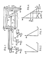
- the gripper comprises a double-acting pneumatic cylinder 1, a C-shaped frame constituted by a first plate 2 a spacer 3 and a second plate 4 acting as jaw.
- PLate 2 is fixed at the end of cylinder 1 perpendicularly to the stroke direction of cylinder shaft 5.
- PLates 2 and 4 are parallel each other.
- two (or more) grinding bars 6, 7 are fixed paralLeL each other and to the stroke direction of the shaft.
- a bearing plate 8 is fixed, slidably mounted on guiding bars 6, 7 and parallel to plates 2 and 4.
- a single-acting diaphragm pneumatic actuator 9 is fixed to bearing pLa te 8 and its actuation shaft 10 extends towards plate 4.
- a plate 11 acting as jaw is fixed to the free end of shaft 10, and sli dably mounted on bars 6, 7 parallel to plate 4.
- the two plates-jaws 4 and 11 have two gripping beaks 12, 13 faced each other and suitably shaped.
- CyLinder 1 and the frame constitute a stiff set which can be suitably fixed to the end of a robot arm, for instance by means of a threaded pin 14 arranged at one end of cylirider 1, or by fixing the spacer 3 to the robot arm.
- the Robot can therefore shift the gripper within the spaciaL coordina tes according to the received instructions, in order that jaw 4 reaches a preestablished position.
- Jaw 4 is integral to the robot arm and therefore in a relative fixed position. ALL the shifts controtted by the robot are referred to such position.
- InLet 15 of cylinder 1 back chamber is connected to a pressure source P1, through electric valve 16.
- ELectric valve 16 is controlled by an electric signal S1.
- inlet 17 of front chamber is connected through electric valve 18 to a pressure source P2 which, for sake of simplicity, is consider ed equal to P1.
- ELectricaL valve 18 is controLLed by electric signal S2.
- the single acting pneumatic actuator 9 is obviously provided-with onLy one inlet 19 connected, through an electric valve 20, to a pressure source P3 which is considered equal to P1, for simplicity sake.
- Electric valve 20 is controlled by an electric signal S3.
- the stroke of cylinder 1 shaft 5 is preferably of 50 mm.
- the stroke of diaphragm actuator 9 shaft 10 is preferably of few millime ters, for instance 4.
- jaw 1 shifts are caused by the combined operation of cylinder 1 and actuator 9'and that the control of cylinder 1 allows shifts ranging from 0 to 50.mm., while the control of actuator 9 adds to-such shifts a further shift ranging from 0 to 4 mm.
- a double-acting pneumatic cylinder is an actuation means characteriz ed by a great internal friction and therefore a very Limited sensiti vity to external forces applied to the shaft.
- the shaft movement is given by a minimum force at Least in the order of hundreds of grams or one kilogram.
- the section of the two chambers differs by the shaft section.
- the behaviour of the diaphragm actuator is compLeteLy different.
- Fig. 2 and 3 shows in qualitative diagram the behaviour of a diaphragm actuator.
- ParticuLarLy Fig. 2 shows that, Lacking external Loads the shaft shift ing as to the rest position is substantially proportional to the feed ing pressure P, that is it shows that the diaphragm exerts an elastic internal reaction proportional to X.
- shaft 5 bearing plate 8 diaphragm actuator 9 and jaw 11 are completely shifted Leftwards, in a rest position, cor responding to the maximum opening of the jaws and the beaks that is 50 mm.
- the so-opened gripper is positioned by the robot in correspondence of the piece to be gripped, that is fixed jaw 4 is positioned in order that its internal side contact a side of the piece to be gripped.
- the piece is obviously positioned at the Left of a jaw 4.
- Yaw 11 is shifted rightwards with a stroke of about 4 mm..equal to the maximum stroke of the diaphragm actuator.
- Shift ⁇ X in the order of millimeters, is shown by diagram of fig.4 which relates the useful thrust F of the cylinder to the variable thrust FA of the diaphragm actuator.
- the piece stays in a Locked status owing to thrust F still exerted by the diaphragm actuator, while cylinder 1 piston is Locked in a stable position by the frictions.
- the shift is such that diaphragm actuator 9 expands until the thrust exerted by the actuator on the piece faLLs to value F 1 .
- the shift can be slightly higher but in any case of about tenths of millimeters or at the maximum of mm., and the gripping force arising can be slightly Lower than F 1 .
- the gripped piece can be moved by the robots to the preestablished point.
- the piece release is obtained by removing signal S3 so allowing actua tor 9 to reach the rest status.
- the shift is quantitatively defined by values ⁇ X2 or ⁇ X3 evidenced in diagram of fig. 4, and is of about 1 - 2 mm.
- the feeding pressure can be different for the two cyli D der chambers and for the actuator chamber.
- feeding pressure P2 of the front chamber of the cylinder can be Lower than the feeding pressure P1 of the back chamber (or expansion chamber) in order that two opposed thrustes, acting on the piston, cause a closing thrust Lower than F but opposed to the reaction exerted by the gripped piece in order to increase the stability range when gripping.
- the gripping force is defined by the upper Limit of minimum force F 1 required to overcome the piston friction.
- the gripper of fig. 5 differs from the one of fig. 1 because a Locking electric valve 36 is positioned between inlet 15 and electric valve 16 and a Locking electric valve 38 is positioned between inlet 17 and electric valve 18.
- ELectric valves 36 and 38 are controlled by an electric signal S4 and-S5 respectively.
- the pressure LeveL P1 within the two chambers can be maintained very high and the autoprogramming operation is obtained by putting in pressure the two chambers with the sa me pressure value and then by Locking them by means of electric valves 36 and 38.
Landscapes
- Engineering & Computer Science (AREA)
- Robotics (AREA)
- Mechanical Engineering (AREA)
- Manufacturing & Machinery (AREA)
- Microelectronics & Electronic Packaging (AREA)
- Manipulator (AREA)
Applications Claiming Priority (2)
| Application Number | Priority Date | Filing Date | Title |
|---|---|---|---|
| IT2112885 | 1985-06-12 | ||
| IT21128/85A IT1200642B (it) | 1985-06-12 | 1985-06-12 | Pinza pneumatica autoprogrammante |
Publications (3)
| Publication Number | Publication Date |
|---|---|
| EP0205141A2 true EP0205141A2 (de) | 1986-12-17 |
| EP0205141A3 EP0205141A3 (en) | 1989-05-17 |
| EP0205141B1 EP0205141B1 (de) | 1991-12-18 |
Family
ID=11177152
Family Applications (1)
| Application Number | Title | Priority Date | Filing Date |
|---|---|---|---|
| EP86107853A Expired - Lifetime EP0205141B1 (de) | 1985-06-12 | 1986-06-09 | Selbstprogrammierter pneumatischer Greifer |
Country Status (3)
| Country | Link |
|---|---|
| EP (1) | EP0205141B1 (de) |
| DE (1) | DE3682952D1 (de) |
| IT (1) | IT1200642B (de) |
Cited By (6)
| Publication number | Priority date | Publication date | Assignee | Title |
|---|---|---|---|---|
| WO1992020496A1 (de) * | 1991-05-15 | 1992-11-26 | Mohammad Mohsen Saadat | Greifermechanismus |
| WO2017059839A1 (de) * | 2015-10-05 | 2017-04-13 | Martin Zimmer | Greifvorrichtung mit integriertem regler |
| CN108375998A (zh) * | 2018-03-15 | 2018-08-07 | 宁波尚进自动化科技有限公司 | 一种具有摩擦力的线夹开关状态控制方法及系统 |
| EP3643458A3 (de) * | 2018-09-04 | 2020-07-29 | KUIPERS technologies GmbH | Greifvorrichtung zum greifen von metallblechen |
| US11007653B2 (en) | 2016-10-04 | 2021-05-18 | Martin Zimmer | Gripping device having a switching module |
| JP2021191599A (ja) * | 2020-06-05 | 2021-12-16 | オークマ株式会社 | グリッパ装置 |
Families Citing this family (1)
| Publication number | Priority date | Publication date | Assignee | Title |
|---|---|---|---|---|
| DE102017106428A1 (de) * | 2017-03-24 | 2018-09-27 | Schunk Gmbh & Co. Kg Spann- Und Greiftechnik | Linear-, Greif-, Spann-, Dreh- oder Schwenkvorrichtung und Verfahren zum Betreiben einer derartigen Vorrichtung |
Family Cites Families (3)
| Publication number | Priority date | Publication date | Assignee | Title |
|---|---|---|---|---|
| JPS594272B2 (ja) * | 1979-06-30 | 1984-01-28 | ファナック株式会社 | ワ−ク把持装置 |
| US4456293A (en) * | 1982-08-24 | 1984-06-26 | International Business Machines Corporation | Article gripping apparatus |
| DE3312483A1 (de) * | 1983-04-07 | 1984-10-11 | Blohm + Voss Ag, 2000 Hamburg | Greifer fuer industrieroboter |
-
1985
- 1985-06-12 IT IT21128/85A patent/IT1200642B/it active
-
1986
- 1986-06-09 DE DE8686107853T patent/DE3682952D1/de not_active Expired - Lifetime
- 1986-06-09 EP EP86107853A patent/EP0205141B1/de not_active Expired - Lifetime
Cited By (12)
| Publication number | Priority date | Publication date | Assignee | Title |
|---|---|---|---|---|
| WO1992020496A1 (de) * | 1991-05-15 | 1992-11-26 | Mohammad Mohsen Saadat | Greifermechanismus |
| US5484181A (en) * | 1991-05-15 | 1996-01-16 | Saadat; Mohsen M. | Gripper mechanism |
| WO2017059839A1 (de) * | 2015-10-05 | 2017-04-13 | Martin Zimmer | Greifvorrichtung mit integriertem regler |
| CN108136581A (zh) * | 2015-10-05 | 2018-06-08 | 马丁·齐默尔 | 具有集成的控制装置的夹持装置 |
| EP3359351B1 (de) | 2015-10-05 | 2021-08-25 | Martin Zimmer | Greifvorrichtung mit integriertem regler |
| CN108136581B (zh) * | 2015-10-05 | 2021-11-02 | 马丁·齐默尔 | 具有集成的控制装置的夹持装置 |
| US11007653B2 (en) | 2016-10-04 | 2021-05-18 | Martin Zimmer | Gripping device having a switching module |
| CN108375998A (zh) * | 2018-03-15 | 2018-08-07 | 宁波尚进自动化科技有限公司 | 一种具有摩擦力的线夹开关状态控制方法及系统 |
| CN108375998B (zh) * | 2018-03-15 | 2024-05-17 | 宁波尚进自动化科技有限公司 | 一种具有摩擦力的线夹开关状态控制方法及系统 |
| EP3643458A3 (de) * | 2018-09-04 | 2020-07-29 | KUIPERS technologies GmbH | Greifvorrichtung zum greifen von metallblechen |
| JP2021191599A (ja) * | 2020-06-05 | 2021-12-16 | オークマ株式会社 | グリッパ装置 |
| US12076852B2 (en) | 2020-06-05 | 2024-09-03 | Okuma Corporation | Gripper device |
Also Published As
| Publication number | Publication date |
|---|---|
| DE3682952D1 (de) | 1992-01-30 |
| IT8521128A0 (it) | 1985-06-12 |
| EP0205141B1 (de) | 1991-12-18 |
| EP0205141A3 (en) | 1989-05-17 |
| IT1200642B (it) | 1989-01-27 |
Similar Documents
| Publication | Publication Date | Title |
|---|---|---|
| US4699414A (en) | Multi use gripper for industrial robot | |
| US4620362A (en) | Changeable tooling system for robot end-effector | |
| EP0396210B1 (de) | Handmechanismus | |
| US5360249A (en) | Multifunctional end effectors | |
| US4789292A (en) | End effector for robotic equipment | |
| EP0205141A2 (de) | Selbstprogrammierter pneumatischer Greifer | |
| US4996753A (en) | Robot end effector exchange system | |
| US4730862A (en) | Pneumatic, tactile gripper generating a gripping force controlled by the weight of the handled object | |
| Schmidt | Flexible moulding jaws for grippers | |
| JPH06190764A (ja) | 把持機構 | |
| CN217046455U (zh) | 一种用于自动上下料的柔性双工位手爪 | |
| JPH0112635B2 (de) | ||
| EP0062071B1 (de) | Durchgehende doppelhand | |
| JPH02190285A (ja) | ロボット用ハンド | |
| CN114347082A (zh) | 一种用于自动上下料的柔性双工位手爪 | |
| EP0173234A1 (de) | Robotergreifer | |
| SU1433789A1 (ru) | Рука промышленного робота | |
| SU1093551A2 (ru) | Схват манипул ционного робота | |
| CN221818686U (zh) | 一种基于机器人的低压夹爪 | |
| JPH071240Y2 (ja) | 把持装置 | |
| Jeswiet et al. | A Robot Kinematic Gripper | |
| JPH0357437Y2 (de) | ||
| SU1414633A1 (ru) | Захватна головка | |
| Schneider et al. | Robot grippers in systems projects | |
| SU1315298A1 (ru) | Адаптивный захват робота-манипул тора |
Legal Events
| Date | Code | Title | Description |
|---|---|---|---|
| PUAI | Public reference made under article 153(3) epc to a published international application that has entered the european phase |
Free format text: ORIGINAL CODE: 0009012 |
|
| AK | Designated contracting states |
Kind code of ref document: A2 Designated state(s): DE FR GB |
|
| RAP1 | Party data changed (applicant data changed or rights of an application transferred) |
Owner name: HONEYWELL BULL ITALIA S.P.A. |
|
| PUAL | Search report despatched |
Free format text: ORIGINAL CODE: 0009013 |
|
| AK | Designated contracting states |
Kind code of ref document: A3 Designated state(s): DE FR GB |
|
| RAP1 | Party data changed (applicant data changed or rights of an application transferred) |
Owner name: BULL HN INFORMATION SYSTEMS ITALIA S.P.A. |
|
| 17P | Request for examination filed |
Effective date: 19890605 |
|
| 17Q | First examination report despatched |
Effective date: 19910204 |
|
| GRAA | (expected) grant |
Free format text: ORIGINAL CODE: 0009210 |
|
| AK | Designated contracting states |
Kind code of ref document: B1 Designated state(s): DE FR GB |
|
| REF | Corresponds to: |
Ref document number: 3682952 Country of ref document: DE Date of ref document: 19920130 |
|
| ET | Fr: translation filed | ||
| PGFP | Annual fee paid to national office [announced via postgrant information from national office to epo] |
Ref country code: DE Payment date: 19920413 Year of fee payment: 7 |
|
| PGFP | Annual fee paid to national office [announced via postgrant information from national office to epo] |
Ref country code: GB Payment date: 19920505 Year of fee payment: 7 |
|
| PGFP | Annual fee paid to national office [announced via postgrant information from national office to epo] |
Ref country code: FR Payment date: 19920625 Year of fee payment: 7 |
|
| PLBE | No opposition filed within time limit |
Free format text: ORIGINAL CODE: 0009261 |
|
| STAA | Information on the status of an ep patent application or granted ep patent |
Free format text: STATUS: NO OPPOSITION FILED WITHIN TIME LIMIT |
|
| 26N | No opposition filed | ||
| PG25 | Lapsed in a contracting state [announced via postgrant information from national office to epo] |
Ref country code: GB Effective date: 19930609 |
|
| GBPC | Gb: european patent ceased through non-payment of renewal fee |
Effective date: 19930609 |
|
| PG25 | Lapsed in a contracting state [announced via postgrant information from national office to epo] |
Ref country code: FR Effective date: 19940228 |
|
| PG25 | Lapsed in a contracting state [announced via postgrant information from national office to epo] |
Ref country code: DE Effective date: 19940301 |
|
| REG | Reference to a national code |
Ref country code: FR Ref legal event code: ST |