EP0205141A2 - Autoprogramming pneumatic gripper - Google Patents
Autoprogramming pneumatic gripper Download PDFInfo
- Publication number
- EP0205141A2 EP0205141A2 EP86107853A EP86107853A EP0205141A2 EP 0205141 A2 EP0205141 A2 EP 0205141A2 EP 86107853 A EP86107853 A EP 86107853A EP 86107853 A EP86107853 A EP 86107853A EP 0205141 A2 EP0205141 A2 EP 0205141A2
- Authority
- EP
- European Patent Office
- Prior art keywords
- cylinder
- jaw
- actuator
- gripping
- shaft
- Prior art date
- Legal status (The legal status is an assumption and is not a legal conclusion. Google has not performed a legal analysis and makes no representation as to the accuracy of the status listed.)
- Granted
Links
- 230000008602 contraction Effects 0.000 claims description 2
- 238000003780 insertion Methods 0.000 abstract description 7
- 230000037431 insertion Effects 0.000 abstract description 7
- 238000010586 diagram Methods 0.000 description 6
- 230000035611 feeding Effects 0.000 description 6
- 238000006243 chemical reaction Methods 0.000 description 4
- 210000003323 beak Anatomy 0.000 description 2
- 230000000875 corresponding effect Effects 0.000 description 2
- 238000000034 method Methods 0.000 description 2
- 125000006850 spacer group Chemical group 0.000 description 2
- 101100116570 Caenorhabditis elegans cup-2 gene Proteins 0.000 description 1
- 241001052209 Cylinder Species 0.000 description 1
- 101100116572 Drosophila melanogaster Der-1 gene Proteins 0.000 description 1
- 208000036366 Sensation of pressure Diseases 0.000 description 1
- 230000007423 decrease Effects 0.000 description 1
- 238000007599 discharging Methods 0.000 description 1
- 238000006073 displacement reaction Methods 0.000 description 1
- 230000000694 effects Effects 0.000 description 1
- 238000009472 formulation Methods 0.000 description 1
- 239000000203 mixture Substances 0.000 description 1
- 230000004048 modification Effects 0.000 description 1
- 238000012986 modification Methods 0.000 description 1
- 230000035945 sensitivity Effects 0.000 description 1
Images

Classifications
-
- B—PERFORMING OPERATIONS; TRANSPORTING
- B25—HAND TOOLS; PORTABLE POWER-DRIVEN TOOLS; MANIPULATORS
- B25J—MANIPULATORS; CHAMBERS PROVIDED WITH MANIPULATION DEVICES
- B25J15/00—Gripping heads and other end effectors
- B25J15/02—Gripping heads and other end effectors servo-actuated
- B25J15/0253—Gripping heads and other end effectors servo-actuated comprising parallel grippers
-
- B—PERFORMING OPERATIONS; TRANSPORTING
- B25—HAND TOOLS; PORTABLE POWER-DRIVEN TOOLS; MANIPULATORS
- B25J—MANIPULATORS; CHAMBERS PROVIDED WITH MANIPULATION DEVICES
- B25J9/00—Programme-controlled manipulators
- B25J9/10—Programme-controlled manipulators characterised by positioning means for manipulator elements
- B25J9/14—Programme-controlled manipulators characterised by positioning means for manipulator elements fluid
- B25J9/144—Linear actuators
-
- H—ELECTRICITY
- H05—ELECTRIC TECHNIQUES NOT OTHERWISE PROVIDED FOR
- H05K—PRINTED CIRCUITS; CASINGS OR CONSTRUCTIONAL DETAILS OF ELECTRIC APPARATUS; MANUFACTURE OF ASSEMBLAGES OF ELECTRICAL COMPONENTS
- H05K13/00—Apparatus or processes specially adapted for manufacturing or adjusting assemblages of electric components
- H05K13/04—Mounting of components, e.g. of leadless components
- H05K13/0404—Pick-and-place heads or apparatus, e.g. with jaws
- H05K13/0408—Incorporating a pick-up tool
Definitions
- the present invention relates to an autoprogramming pneumatic gripper particularly devoted to the insertion-of components on printed wiring plates.
- Such apparatuses can operate only with electrical components having preestablished size.
- the automatic insertion apparatuses must be provided with a gripping and handling tool of the components different for each phase.
- Some grippers are provided with sophisticated control means with posi tion sensors which supply feedback signals enabling to change the opening or closing width of the grippers according to the needs.
- pneumatic grippers which grippers are always opened at their maximum for the gripping and the release and which close up to exert a grip, the closing position being established by the handled piece size.
- the grippers must be designed to perform an opening/cLosing stroke of few millimeters, so that its use is Limited to the components whose sizes vary within the same range.
- the autoprogramming pneumatic gripper object of the present invention overcomes such inconvenient enabling the handling of components with a size variability of centimeters, reLeasing the components with a stroke of few millimeters and being controlled in order to remember a required opening condition for the execution of subsequent operations.
- the gripper may be defined as autoprogramming.
- the pneumatic cylinder body is integral to a gripper jaw and the diaphragm actuator shaft is integral to the other jaw.
- the conbined control of the two actuators allows the jaw positioning in order to grip any piece having a size varying from 0 to some centi meters, while the piece release and the subsequent gripping of other pieces with equal size is enabled by the control of the diaphragm ac tuator only.
- the gripper comprises a double-acting pneumatic cylinder 1, a C-shaped frame constituted by a first plate 2 a spacer 3 and a second plate 4 acting as jaw.
- PLate 2 is fixed at the end of cylinder 1 perpendicularly to the stroke direction of cylinder shaft 5.
- PLates 2 and 4 are parallel each other.
- two (or more) grinding bars 6, 7 are fixed paralLeL each other and to the stroke direction of the shaft.
- a bearing plate 8 is fixed, slidably mounted on guiding bars 6, 7 and parallel to plates 2 and 4.
- a single-acting diaphragm pneumatic actuator 9 is fixed to bearing pLa te 8 and its actuation shaft 10 extends towards plate 4.
- a plate 11 acting as jaw is fixed to the free end of shaft 10, and sli dably mounted on bars 6, 7 parallel to plate 4.
- the two plates-jaws 4 and 11 have two gripping beaks 12, 13 faced each other and suitably shaped.
- CyLinder 1 and the frame constitute a stiff set which can be suitably fixed to the end of a robot arm, for instance by means of a threaded pin 14 arranged at one end of cylirider 1, or by fixing the spacer 3 to the robot arm.
- the Robot can therefore shift the gripper within the spaciaL coordina tes according to the received instructions, in order that jaw 4 reaches a preestablished position.
- Jaw 4 is integral to the robot arm and therefore in a relative fixed position. ALL the shifts controtted by the robot are referred to such position.
- InLet 15 of cylinder 1 back chamber is connected to a pressure source P1, through electric valve 16.
- ELectric valve 16 is controlled by an electric signal S1.
- inlet 17 of front chamber is connected through electric valve 18 to a pressure source P2 which, for sake of simplicity, is consider ed equal to P1.
- ELectricaL valve 18 is controLLed by electric signal S2.
- the single acting pneumatic actuator 9 is obviously provided-with onLy one inlet 19 connected, through an electric valve 20, to a pressure source P3 which is considered equal to P1, for simplicity sake.
- Electric valve 20 is controlled by an electric signal S3.
- the stroke of cylinder 1 shaft 5 is preferably of 50 mm.
- the stroke of diaphragm actuator 9 shaft 10 is preferably of few millime ters, for instance 4.
- jaw 1 shifts are caused by the combined operation of cylinder 1 and actuator 9'and that the control of cylinder 1 allows shifts ranging from 0 to 50.mm., while the control of actuator 9 adds to-such shifts a further shift ranging from 0 to 4 mm.
- a double-acting pneumatic cylinder is an actuation means characteriz ed by a great internal friction and therefore a very Limited sensiti vity to external forces applied to the shaft.
- the shaft movement is given by a minimum force at Least in the order of hundreds of grams or one kilogram.
- the section of the two chambers differs by the shaft section.
- the behaviour of the diaphragm actuator is compLeteLy different.
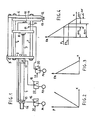
- Fig. 2 and 3 shows in qualitative diagram the behaviour of a diaphragm actuator.
- ParticuLarLy Fig. 2 shows that, Lacking external Loads the shaft shift ing as to the rest position is substantially proportional to the feed ing pressure P, that is it shows that the diaphragm exerts an elastic internal reaction proportional to X.
- shaft 5 bearing plate 8 diaphragm actuator 9 and jaw 11 are completely shifted Leftwards, in a rest position, cor responding to the maximum opening of the jaws and the beaks that is 50 mm.
- the so-opened gripper is positioned by the robot in correspondence of the piece to be gripped, that is fixed jaw 4 is positioned in order that its internal side contact a side of the piece to be gripped.
- the piece is obviously positioned at the Left of a jaw 4.
- Yaw 11 is shifted rightwards with a stroke of about 4 mm..equal to the maximum stroke of the diaphragm actuator.
- Shift ⁇ X in the order of millimeters, is shown by diagram of fig.4 which relates the useful thrust F of the cylinder to the variable thrust FA of the diaphragm actuator.
- the piece stays in a Locked status owing to thrust F still exerted by the diaphragm actuator, while cylinder 1 piston is Locked in a stable position by the frictions.
- the shift is such that diaphragm actuator 9 expands until the thrust exerted by the actuator on the piece faLLs to value F 1 .
- the shift can be slightly higher but in any case of about tenths of millimeters or at the maximum of mm., and the gripping force arising can be slightly Lower than F 1 .
- the gripped piece can be moved by the robots to the preestablished point.
- the piece release is obtained by removing signal S3 so allowing actua tor 9 to reach the rest status.
- the shift is quantitatively defined by values ⁇ X2 or ⁇ X3 evidenced in diagram of fig. 4, and is of about 1 - 2 mm.
- the feeding pressure can be different for the two cyli D der chambers and for the actuator chamber.
- feeding pressure P2 of the front chamber of the cylinder can be Lower than the feeding pressure P1 of the back chamber (or expansion chamber) in order that two opposed thrustes, acting on the piston, cause a closing thrust Lower than F but opposed to the reaction exerted by the gripped piece in order to increase the stability range when gripping.
- the gripping force is defined by the upper Limit of minimum force F 1 required to overcome the piston friction.
- the gripper of fig. 5 differs from the one of fig. 1 because a Locking electric valve 36 is positioned between inlet 15 and electric valve 16 and a Locking electric valve 38 is positioned between inlet 17 and electric valve 18.
- ELectric valves 36 and 38 are controlled by an electric signal S4 and-S5 respectively.
- the pressure LeveL P1 within the two chambers can be maintained very high and the autoprogramming operation is obtained by putting in pressure the two chambers with the sa me pressure value and then by Locking them by means of electric valves 36 and 38.
Abstract
Description
- The present invention relates to an autoprogramming pneumatic gripper particularly devoted to the insertion-of components on printed wiring plates.
- Automatic apparatus for the insertion of electronic components on prin ted wiring plates have been known for a Long time.
- Such apparatuses can operate only with electrical components having preestablished size.
- In the case components of different size have to be inserted on the PWB, the insertion process must be cut into separate phases.
- The automatic insertion apparatuses must be provided with a gripping and handling tool of the components different for each phase.
- In alternative, the automatic insertion process must be performed by means of different apparatuses.
- With the advent of the so-called "robotic" or flexible automation, versatile apparatuses have been put on the market which are able to carry out operations such as: gripping, arrangement, assembling of different elements. They can also be used for the automatic insertion of components on PWB.
- These apparatuses or "Robots" are provided with electrically, pneumati cally or hydraulically controlled grippers susceptible to be variably opened and therefore able to handle components having different sizes provided smaller than the maximum opening of the grippers.
- Some grippers are provided with sophisticated control means with posi tion sensors which supply feedback signals enabling to change the opening or closing width of the grippers according to the needs.
- Such kind of grippers are very expensive and relatively slow in their .operation.
- In practice the use of pneumatic grippers is preferred, which grippers are always opened at their maximum for the gripping and the release and which close up to exert a grip, the closing position being established by the handled piece size.
- The use of such grippers for the insertion of components on PWB is li mited by the fact that, in the release of the component just inserted on the PWB, the gripper fingers or jaws must not touch the components already present on the PWBs, therefore, the release operation must be performed with a minimum opening of the gripper as to the gripping po sition.
- This is required because the components are mounted on the PWBs.the one next to the other at a distance which, in some cases, does not exceed the few mittimeters.
- Therefore the grippers must be designed to perform an opening/cLosing stroke of few millimeters, so that its use is Limited to the components whose sizes vary within the same range.
- The autoprogramming pneumatic gripper object of the present invention overcomes such inconvenient enabling the handling of components with a size variability of centimeters, reLeasing the components with a stroke of few millimeters and being controlled in order to remember a required opening condition for the execution of subsequent operations. In this sense the gripper may be defined as autoprogramming. - These results are achieved by the gri-pper object of the present inven tion through the serial or cascade use of double-acting pneumatic cyLinder with a stroke of centimeters, whose shaft is connected to a single-acting pneumatic actuator, preferably of the diaphragm type, having a stroke of mittimeters.
- The pneumatic cylinder body is integral to a gripper jaw and the diaphragm actuator shaft is integral to the other jaw.
- The conbined control of the two actuators allows the jaw positioning in order to grip any piece having a size varying from 0 to some centi meters, while the piece release and the subsequent gripping of other pieces with equal size is enabled by the control of the diaphragm ac tuator only.
- These and other features of the invention will appear clearly form the following description of a preferred embodiment and from the enclosed drawings where:
- Figure 1 shows an autoprogramming pneumatic gripper embodied according to the invention;
- Figre 2, 3 shows in diagram the functional characteristics of a diaphragm pneumatic actuator;
- Figure 4 shows in diagram the operation of the gripper of fig. 1;
- Figure 5 shows a modification to the gripper of Fig. 1.
- Figure 1 shows in side view a preferred embodiment of the pneumatic gripper of the invention.
- The gripper comprises a double-acting pneumatic cylinder 1, a C-shaped frame constituted by a first plate 2 a spacer 3 and a
second plate 4 acting as jaw. - PLate 2 is fixed at the end of cylinder 1 perpendicularly to the stroke direction of cylinder shaft 5.
-
PLates 2 and 4 are parallel each other. - Between the plates, two (or more)
grinding bars - At the end of cylinder shaft 5 a
bearing plate 8 is fixed, slidably mounted on guidingbars plates 2 and 4. - A single-acting diaphragm
pneumatic actuator 9 is fixed to bearing pLa te 8 and itsactuation shaft 10 extends towardsplate 4. - A
plate 11 acting as jaw, is fixed to the free end ofshaft 10, and sli dably mounted onbars plate 4. - .The two plates-
jaws beaks - CyLinder 1 and the frame constitute a stiff set which can be suitably fixed to the end of a robot arm, for instance by means of a threaded
pin 14 arranged at one end of cylirider 1, or by fixing the spacer 3 to the robot arm. - The Robot can therefore shift the gripper within the spaciaL coordina tes according to the received instructions, in order that
jaw 4 reaches a preestablished position. - Jaw 4 is integral to the robot arm and therefore in a relative fixed position. ALL the shifts controtted by the robot are referred to such position.
-
InLet 15 of cylinder 1 back chamber is connected to a pressure source P1, throughelectric valve 16. -
ELectric valve 16 is controlled by an electric signal S1. - When S1 is present (S1=1) the back chamber is connected to pressure source P and therefore put and kept in pressure.
- When S1 is not present (S1=0) the back chamber is connected to the at mosphere and therefore released and kept released.
- Likewise
inlet 17 of front chamber is connected throughelectric valve 18 to a pressure source P2 which, for sake of simplicity, is consider ed equal to P1. -
ELectricaL valve 18 is controLLed by electric signal S2. - When S2 is present (S2=1) the front chamber is put and kept in pressu re.
- When S2 is not present (S2=0) the front chamber is released and kept released.
- The single acting
pneumatic actuator 9 is obviously provided-with onLy oneinlet 19 connected, through anelectric valve 20, to a pressure source P3 which is considered equal to P1, for simplicity sake.Electric valve 20 is controlled by an electric signal S3. - When S3 is present (S3=1) the actuator is put and kept in pressure. When S3 is not present (S3=0) the actuator is released and kept reLeased.
- The stroke of cylinder 1 shaft 5 is preferably of 50 mm., while the stroke of
diaphragm actuator 9shaft 10 is preferably of few millime ters, forinstance 4. - From the consideration of fig. 1 it clearly appears that jaw 1 shifts are caused by the combined operation of cylinder 1 and actuator 9'and that the control of cylinder 1 allows shifts ranging from 0 to 50.mm., while the control of
actuator 9 adds to-such shifts a further shift ranging from 0 to 4 mm. - Now, to understand the operation of the disclosed gripper as concerns the autoprogrammed position and the grip of electrical components or, more generally, of pieces, it is suitable to remind some features of the used actuators.
- A double-acting pneumatic cylinder is an actuation means characteriz ed by a great internal friction and therefore a very Limited sensiti vity to external forces applied to the shaft.
- For instance if the cylinder is not fed, the shaft movement is given by a minimum force at Least in the order of hundreds of grams or one kilogram.
- On the contrary, Lacking external Loads, the shaft movement is given by a minimum thrust or force of the same order of magnitude, and the-- refore the application of a pressure difference ΔP to the chambers, so that ΔPS≥F1, where S is the chamber section and F1 the minimum force required to overcome the internal friction.
- For an exact formulation it is to be noted that the section of the two chambers differs by the shaft section.
- However, the internal friction effect is so relevant as to allow a sim -plification and, for a wide pressure range P the force F exerted by the cylinder can be expressed as follows:

- Such force, depending on ΔP is not affected by the position of the cylinder piston, that is by the shaft position.
- The behaviour of the diaphragm actuator is compLeteLy different.
- The internal friction of such actuator is negligible, while the exert ed force widely depends on the shaft position.
- Fig. 2 and 3 shows in qualitative diagram the behaviour of a diaphragm actuator.
- ParticuLarLy Fig. 2 shows that, Lacking external Loads the shaft shift ing as to the rest position is substantially proportional to the feed ing pressure P, that is it shows that the diaphragm exerts an elastic internal reaction proportional to X.
- Owing to such reaction the force FA exerted on the shaft is not co- stant but, keeping the feeding pressure equaL, such force decreases according to the shaft displacement from its rest position, as shown by fig. 3.
- After these assumption it will be easy to understand the behaviour of the disclosed gripper and how it can be autoprogrammed for the grip and the release of pieces of any size, such release being effected with a minimum opening of the jaws.
- The gripper can be initially reset with the jaws completely opened, by command S2=1, which put the front chamber of cylinder 1 in pressu re, whilst S1=0.
- With reference to fig. 1, shaft 5
bearing plate 8,diaphragm actuator 9 andjaw 11 are completely shifted Leftwards, in a rest position, cor responding to the maximum opening of the jaws and the beaks that is 50 mm. - Once this operation is carried out, command S2 is removed (S2=O).
- The so-opened gripper is positioned by the robot in correspondence of the piece to be gripped, that is fixed
jaw 4 is positioned in order that its internal side contact a side of the piece to be gripped. - With reference to fig. 1, the piece is obviously positioned at the Left of a
jaw 4. - The diaphragm actuator is fed and kept in pressure by command S3=1.
Yaw 11 is shifted rightwards with a stroke of about 4 mm..equal to the maximum stroke of the diaphragm actuator. - Straight after, the back chamber of cylinder 1 is put in pressure by com mand S1=1 and
plate 8,actuator 9 andjaw 11 shift jointly rightwards up tojaw 11 contacts the Left side of the piece. - At this
point plate 8 andactuator 9 continue their rightwards stroke for a quantity ΔX whilejaw 11 grips the piece. - In other words a relative shift occurs between
actuator 9 andjaw 11, until the gripping force exerted on the piece becomes equal to the thrust F of the cylinder. - Shift ΔX, in the order of millimeters, is shown by diagram of fig.4 which relates the useful thrust F of the cylinder to the variable thrust FA of the diaphragm actuator.
- Without removing signal S1=1, signal S2=1 puts in pressure the front chamber of cylinder 1 and thrust F exerted by the cylinder becomes nuL At this point two possibilities may occur:
- If thrust F previously exerted is Lower than thrust F1, necessary to the piston shift, the piston does not move.
- The piece stays in a Locked status owing to thrust F still exerted by the diaphragm actuator, while cylinder 1 piston is Locked in a stable position by the frictions.
- If thrust F is higher than thrust F1 the reaction of equal value exert ed between gripped piece and diaphragm actuator causes a LittLe shift (Leftwards, with reference to fig. 1) of
actuator 9,plate 8 and shaft 5 and related piston. - The shift is such that
diaphragm actuator 9 expands until the thrust exerted by the actuator on the piece faLLs to value F1. - The shift is therefore evidenced by the value ΔX1 shown by diagram of fig. 4.
- Actually, owing to the system inertia, the shift can be slightly higher but in any case of about tenths of millimeters or at the maximum of mm., and the gripping force arising can be slightly Lower than F1.
- At the end of such shift both the gripped piece and the cylinder piston are steadily positioned.
- When all signals S1, S2, S3 are present, the gripped piece can be moved by the robots to the preestablished point.
- The piece release is obtained by removing signal S3 so allowing
actua tor 9 to reach the rest status. - occurs A Leftwards shifting therefore (with reference to fig. 1) of
jaw 11 within the actuator stroke. - Depending on whether the grip thrust was F < F1 or F1 the shift is quantitatively defined by values ΔX2 or ΔX3 evidenced in diagram of fig. 4, and is of about 1-2 mm.
- With this shift of
jaw 11 the piece release takes place without inter ferences of the jaw with contiguous pieces. - The operation occurs without shifts of the piston and shaft 5 of cylin der 1 which keeps or "remember" its position for subsequent gripping operations of pieces having equal size.
- If the subsequent pieces to be handled have a size equal or smaLLer than the one of the already positioned piece, the new operation takes place by positioning the gripper on the piece, making
actuator 9 expanded by signal S3=1 and confirming the gripping function of cylinder 1 by removing signal S2. - This causes, if necessary, that is if the piece to be gripped is smal Ler that the one already gripped, a shift of shaft 5,
plate 8,actua tor 9 andjaw 11 up to the actual gripping of the piece. - ALso in this case, with the Locking of cylinder 1 obtained by applying again signal S2=1, the new gripping position is remembered. On the contrary if the subsequent pieces to be handled have Larger size than the piece already gripped, the gripper is moved away from the re Lease zone and the complete opening of the jaws takes place by removing signal S1.
- Then the already mentioned gripping,positioning and release sequence. takes place.
- The previously described embodiment and the related operating modalities only represent one preferred embodiment of the invention and it is clear that several changes can be brought without departing from the scope of the invention.
- In particular the feeding pressure can be different for the two cyliD der chambers and for the actuator chamber.
- For instance feeding pressure P2 of the front chamber of the cylinder (or contraction chamber) can be Lower than the feeding pressure P1 of the back chamber (or expansion chamber) in order that two opposed thrustes, acting on the piston, cause a closing thrust Lower than F but opposed to the reaction exerted by the gripped piece in order to increase the stability range when gripping.
- ALso in this case the gripping force is defined by the upper Limit of minimum force F1 required to overcome the piston friction.
- If gripping forces higher than the ones allowed by F are required, the embodiment shown in fig. 5 can be considered.
- The gripper of fig. 5 differs from the one of fig. 1 because a Locking
electric valve 36 is positioned betweeninlet 15 andelectric valve 16 and a Locking electric valve 38 is positioned betweeninlet 17 andelectric valve 18. - Further
electric valves -
ELectric valves 36 and 38 are controlled by an electric signal S4 and-S5 respectively. - When S4=1
electric valve 36 is opened. - When S4=0
electric valve 36 is closed and it practically seals the back chamber of cylinder 1. - The same control function is carried out by signal S5 on electric val ve 38.
- According to such embodiment, the pressure LeveL P1 within the two chambers can be maintained very high and the autoprogramming operation is obtained by putting in pressure the two chambers with the sa me pressure value and then by Locking them by means of
electric valves 36 and 38. - In these conditions it is clear that any shifting of the piston from a balance initial position causes pressure variations between the two chambers and therefore a thrust unbalance tending to recall the piston towards the initial position.
- The relation between unbalance force and shifting from the initial po sition depends on both the used pressure and the piston position with in the cylinder.
- It is however possible, through a suitable pressure choice, to obtain that, independently from the piston position, the feedback caused by a piston shift as to the balance position be higher than the correspond ing thrust variation exerted by
actuator 9 for an equal shift. - In this way a piston position is assured independently from the friction force and it si possible to preestabLish the gripping force acting on a pie ce according to the difference between feeding pressure of cylinder 1 and discharging pressure.
Claims (3)
Applications Claiming Priority (2)
| Application Number | Priority Date | Filing Date | Title |
|---|---|---|---|
| IT21128/85A IT1200642B (en) | 1985-06-12 | 1985-06-12 | SELF-PROGRAMMING PNEUMATIC CLAMP |
| IT2112885 | 1985-06-12 |
Publications (3)
| Publication Number | Publication Date |
|---|---|
| EP0205141A2 true EP0205141A2 (en) | 1986-12-17 |
| EP0205141A3 EP0205141A3 (en) | 1989-05-17 |
| EP0205141B1 EP0205141B1 (en) | 1991-12-18 |
Family
ID=11177152
Family Applications (1)
| Application Number | Title | Priority Date | Filing Date |
|---|---|---|---|
| EP86107853A Expired - Lifetime EP0205141B1 (en) | 1985-06-12 | 1986-06-09 | Autoprogramming pneumatic gripper |
Country Status (3)
| Country | Link |
|---|---|
| EP (1) | EP0205141B1 (en) |
| DE (1) | DE3682952D1 (en) |
| IT (1) | IT1200642B (en) |
Cited By (4)
| Publication number | Priority date | Publication date | Assignee | Title |
|---|---|---|---|---|
| WO1992020496A1 (en) * | 1991-05-15 | 1992-11-26 | Mohammad Mohsen Saadat | Gripping mechanism |
| WO2017059839A1 (en) * | 2015-10-05 | 2017-04-13 | Martin Zimmer | Gripping device having an integrated controller |
| EP3643458A3 (en) * | 2018-09-04 | 2020-07-29 | KUIPERS technologies GmbH | Gripping device for gripping sheet metal |
| US11007653B2 (en) | 2016-10-04 | 2021-05-18 | Martin Zimmer | Gripping device having a switching module |
Families Citing this family (1)
| Publication number | Priority date | Publication date | Assignee | Title |
|---|---|---|---|---|
| DE102017106428A1 (en) * | 2017-03-24 | 2018-09-27 | Schunk Gmbh & Co. Kg Spann- Und Greiftechnik | Linear, gripping, tensioning, rotating or pivoting device and method for operating such a device |
Citations (3)
| Publication number | Priority date | Publication date | Assignee | Title |
|---|---|---|---|---|
| US4336926A (en) * | 1979-06-30 | 1982-06-29 | Fujitsu Fanuc Limited | Workpiece manipulator |
| US4456293A (en) * | 1982-08-24 | 1984-06-26 | International Business Machines Corporation | Article gripping apparatus |
| DE3312483A1 (en) * | 1983-04-07 | 1984-10-11 | Blohm + Voss Ag, 2000 Hamburg | Gripper for industrial robots |
-
1985
- 1985-06-12 IT IT21128/85A patent/IT1200642B/en active
-
1986
- 1986-06-09 DE DE8686107853T patent/DE3682952D1/en not_active Expired - Lifetime
- 1986-06-09 EP EP86107853A patent/EP0205141B1/en not_active Expired - Lifetime
Patent Citations (3)
| Publication number | Priority date | Publication date | Assignee | Title |
|---|---|---|---|---|
| US4336926A (en) * | 1979-06-30 | 1982-06-29 | Fujitsu Fanuc Limited | Workpiece manipulator |
| US4456293A (en) * | 1982-08-24 | 1984-06-26 | International Business Machines Corporation | Article gripping apparatus |
| DE3312483A1 (en) * | 1983-04-07 | 1984-10-11 | Blohm + Voss Ag, 2000 Hamburg | Gripper for industrial robots |
Cited By (8)
| Publication number | Priority date | Publication date | Assignee | Title |
|---|---|---|---|---|
| WO1992020496A1 (en) * | 1991-05-15 | 1992-11-26 | Mohammad Mohsen Saadat | Gripping mechanism |
| US5484181A (en) * | 1991-05-15 | 1996-01-16 | Saadat; Mohsen M. | Gripper mechanism |
| WO2017059839A1 (en) * | 2015-10-05 | 2017-04-13 | Martin Zimmer | Gripping device having an integrated controller |
| CN108136581A (en) * | 2015-10-05 | 2018-06-08 | 马丁·齐默尔 | Clamping device with integrated control device |
| EP3359351B1 (en) | 2015-10-05 | 2021-08-25 | Martin Zimmer | Gripping device having an integrated controller |
| CN108136581B (en) * | 2015-10-05 | 2021-11-02 | 马丁·齐默尔 | Clamping device with integrated control device |
| US11007653B2 (en) | 2016-10-04 | 2021-05-18 | Martin Zimmer | Gripping device having a switching module |
| EP3643458A3 (en) * | 2018-09-04 | 2020-07-29 | KUIPERS technologies GmbH | Gripping device for gripping sheet metal |
Also Published As
| Publication number | Publication date |
|---|---|
| IT8521128A0 (en) | 1985-06-12 |
| EP0205141B1 (en) | 1991-12-18 |
| EP0205141A3 (en) | 1989-05-17 |
| DE3682952D1 (en) | 1992-01-30 |
| IT1200642B (en) | 1989-01-27 |
Similar Documents
| Publication | Publication Date | Title |
|---|---|---|
| SU1168090A3 (en) | Industrial robot wrist | |
| US4699414A (en) | Multi use gripper for industrial robot | |
| US4620362A (en) | Changeable tooling system for robot end-effector | |
| US5360249A (en) | Multifunctional end effectors | |
| US4367891A (en) | Industrial robot with a gripping mechanism | |
| US4789292A (en) | End effector for robotic equipment | |
| DE102005033767A1 (en) | Device for manipulating workpieces during forging, with a gripper mechanism that can be adjusted to be either pliable or rigid, comprises rollers that advance along contact surfaces to put gripper arms in the rigid position | |
| EP0205141A2 (en) | Autoprogramming pneumatic gripper | |
| CA2338557A1 (en) | An apparatus for performing animal related operations | |
| US4996753A (en) | Robot end effector exchange system | |
| US4730862A (en) | Pneumatic, tactile gripper generating a gripping force controlled by the weight of the handled object | |
| Schmidt | Flexible moulding jaws for grippers | |
| JPH0112635B2 (en) | ||
| EP0062071B1 (en) | Through double hand | |
| JPH06190764A (en) | Gripping mechanism | |
| JPH02190285A (en) | Hand for robot | |
| CN113631331A (en) | Robot gripper and method for operating a robot gripper | |
| SU1433789A1 (en) | Industrial robot hand | |
| JP2638415B2 (en) | Positioning device for heavy objects by the cooperation of the lifting machine and the robot | |
| SU1093551A2 (en) | Manipulating robot grip | |
| CN217046455U (en) | Flexible double-station paw for automatic feeding and discharging | |
| CN216180611U (en) | Double-finger under-actuated gripper | |
| SU1060469A1 (en) | Gripper | |
| JPH071240Y2 (en) | Gripping device | |
| Jeswiet et al. | A Robot Kinematic Gripper |
Legal Events
| Date | Code | Title | Description |
|---|---|---|---|
| PUAI | Public reference made under article 153(3) epc to a published international application that has entered the european phase |
Free format text: ORIGINAL CODE: 0009012 |
|
| AK | Designated contracting states |
Kind code of ref document: A2 Designated state(s): DE FR GB |
|
| RAP1 | Party data changed (applicant data changed or rights of an application transferred) |
Owner name: HONEYWELL BULL ITALIA S.P.A. |
|
| PUAL | Search report despatched |
Free format text: ORIGINAL CODE: 0009013 |
|
| AK | Designated contracting states |
Kind code of ref document: A3 Designated state(s): DE FR GB |
|
| RAP1 | Party data changed (applicant data changed or rights of an application transferred) |
Owner name: BULL HN INFORMATION SYSTEMS ITALIA S.P.A. |
|
| 17P | Request for examination filed |
Effective date: 19890605 |
|
| 17Q | First examination report despatched |
Effective date: 19910204 |
|
| GRAA | (expected) grant |
Free format text: ORIGINAL CODE: 0009210 |
|
| AK | Designated contracting states |
Kind code of ref document: B1 Designated state(s): DE FR GB |
|
| REF | Corresponds to: |
Ref document number: 3682952 Country of ref document: DE Date of ref document: 19920130 |
|
| ET | Fr: translation filed | ||
| PGFP | Annual fee paid to national office [announced via postgrant information from national office to epo] |
Ref country code: DE Payment date: 19920413 Year of fee payment: 7 |
|
| PGFP | Annual fee paid to national office [announced via postgrant information from national office to epo] |
Ref country code: GB Payment date: 19920505 Year of fee payment: 7 |
|
| PGFP | Annual fee paid to national office [announced via postgrant information from national office to epo] |
Ref country code: FR Payment date: 19920625 Year of fee payment: 7 |
|
| PLBE | No opposition filed within time limit |
Free format text: ORIGINAL CODE: 0009261 |
|
| STAA | Information on the status of an ep patent application or granted ep patent |
Free format text: STATUS: NO OPPOSITION FILED WITHIN TIME LIMIT |
|
| 26N | No opposition filed | ||
| PG25 | Lapsed in a contracting state [announced via postgrant information from national office to epo] |
Ref country code: GB Effective date: 19930609 |
|
| GBPC | Gb: european patent ceased through non-payment of renewal fee |
Effective date: 19930609 |
|
| PG25 | Lapsed in a contracting state [announced via postgrant information from national office to epo] |
Ref country code: FR Effective date: 19940228 |
|
| PG25 | Lapsed in a contracting state [announced via postgrant information from national office to epo] |
Ref country code: DE Effective date: 19940301 |
|
| REG | Reference to a national code |
Ref country code: FR Ref legal event code: ST |