EP0204991B1 - Holding device for a wing frame swivelling around an axis with respect to an outer frame - Google Patents
Holding device for a wing frame swivelling around an axis with respect to an outer frame Download PDFInfo
- Publication number
- EP0204991B1 EP0204991B1 EP86106655A EP86106655A EP0204991B1 EP 0204991 B1 EP0204991 B1 EP 0204991B1 EP 86106655 A EP86106655 A EP 86106655A EP 86106655 A EP86106655 A EP 86106655A EP 0204991 B1 EP0204991 B1 EP 0204991B1
- Authority
- EP
- European Patent Office
- Prior art keywords
- sliding member
- casement
- hook
- sliding
- cam
- Prior art date
- Legal status (The legal status is an assumption and is not a legal conclusion. Google has not performed a legal analysis and makes no representation as to the accuracy of the status listed.)
- Expired - Lifetime
Links
Images

Classifications
-
- E—FIXED CONSTRUCTIONS
- E05—LOCKS; KEYS; WINDOW OR DOOR FITTINGS; SAFES
- E05C—BOLTS OR FASTENING DEVICES FOR WINGS, SPECIALLY FOR DOORS OR WINDOWS
- E05C17/00—Devices for holding wings open; Devices for limiting opening of wings or for holding wings open by a movable member extending between frame and wing; Braking devices, stops or buffers, combined therewith
- E05C17/02—Devices for holding wings open; Devices for limiting opening of wings or for holding wings open by a movable member extending between frame and wing; Braking devices, stops or buffers, combined therewith by mechanical means
- E05C17/04—Devices for holding wings open; Devices for limiting opening of wings or for holding wings open by a movable member extending between frame and wing; Braking devices, stops or buffers, combined therewith by mechanical means with a movable bar or equivalent member extending between frame and wing
- E05C17/12—Devices for holding wings open; Devices for limiting opening of wings or for holding wings open by a movable member extending between frame and wing; Braking devices, stops or buffers, combined therewith by mechanical means with a movable bar or equivalent member extending between frame and wing consisting of a single rod
- E05C17/24—Devices for holding wings open; Devices for limiting opening of wings or for holding wings open by a movable member extending between frame and wing; Braking devices, stops or buffers, combined therewith by mechanical means with a movable bar or equivalent member extending between frame and wing consisting of a single rod pivoted at one end, and with the other end running along a guide member
-
- E—FIXED CONSTRUCTIONS
- E05—LOCKS; KEYS; WINDOW OR DOOR FITTINGS; SAFES
- E05B—LOCKS; ACCESSORIES THEREFOR; HANDCUFFS
- E05B63/00—Locks or fastenings with special structural characteristics
- E05B63/04—Locks or fastenings with special structural characteristics for alternative use on the right-hand or left-hand side of wings
-
- Y—GENERAL TAGGING OF NEW TECHNOLOGICAL DEVELOPMENTS; GENERAL TAGGING OF CROSS-SECTIONAL TECHNOLOGIES SPANNING OVER SEVERAL SECTIONS OF THE IPC; TECHNICAL SUBJECTS COVERED BY FORMER USPC CROSS-REFERENCE ART COLLECTIONS [XRACs] AND DIGESTS
- Y10—TECHNICAL SUBJECTS COVERED BY FORMER USPC
- Y10S—TECHNICAL SUBJECTS COVERED BY FORMER USPC CROSS-REFERENCE ART COLLECTIONS [XRACs] AND DIGESTS
- Y10S292/00—Closure fasteners
- Y10S292/47—Sash fasteners
-
- Y—GENERAL TAGGING OF NEW TECHNOLOGICAL DEVELOPMENTS; GENERAL TAGGING OF CROSS-SECTIONAL TECHNOLOGIES SPANNING OVER SEVERAL SECTIONS OF THE IPC; TECHNICAL SUBJECTS COVERED BY FORMER USPC CROSS-REFERENCE ART COLLECTIONS [XRACs] AND DIGESTS
- Y10—TECHNICAL SUBJECTS COVERED BY FORMER USPC
- Y10T—TECHNICAL SUBJECTS COVERED BY FORMER US CLASSIFICATION
- Y10T292/00—Closure fasteners
- Y10T292/08—Bolts
- Y10T292/0886—Sliding and swinging
-
- Y—GENERAL TAGGING OF NEW TECHNOLOGICAL DEVELOPMENTS; GENERAL TAGGING OF CROSS-SECTIONAL TECHNOLOGIES SPANNING OVER SEVERAL SECTIONS OF THE IPC; TECHNICAL SUBJECTS COVERED BY FORMER USPC CROSS-REFERENCE ART COLLECTIONS [XRACs] AND DIGESTS
- Y10—TECHNICAL SUBJECTS COVERED BY FORMER USPC
- Y10T—TECHNICAL SUBJECTS COVERED BY FORMER US CLASSIFICATION
- Y10T292/00—Closure fasteners
- Y10T292/28—Extension link
- Y10T292/289—Slotted bar
- Y10T292/291—Sliding catch
-
- Y—GENERAL TAGGING OF NEW TECHNOLOGICAL DEVELOPMENTS; GENERAL TAGGING OF CROSS-SECTIONAL TECHNOLOGIES SPANNING OVER SEVERAL SECTIONS OF THE IPC; TECHNICAL SUBJECTS COVERED BY FORMER USPC CROSS-REFERENCE ART COLLECTIONS [XRACs] AND DIGESTS
- Y10—TECHNICAL SUBJECTS COVERED BY FORMER USPC
- Y10T—TECHNICAL SUBJECTS COVERED BY FORMER US CLASSIFICATION
- Y10T292/00—Closure fasteners
- Y10T292/28—Extension link
- Y10T292/304—Sliding catch
Definitions
- the invention relates to a device for determining a sash frame rotatable about an axis of rotation on a frame in a predetermined rotational opening position for a door, a window or the like, comprising a display pocket which is articulated at one end to a first of two associated frame legs of the casement frame and the frame by a swivel joint and at its other end to the second of these associated frame legs by a swivel sliding joint with a fork-like slit, Latching means which automatically immobilize the setting of the flap with respect to the frame legs when the sash frame coming from the closed position enters the predetermined rotational opening position, and hand-operated solvents for these latching means.
- Such a device is known from German utility model 84 17 729.
- an opening of the casement is only possible up to the predetermined opening position.
- a further opening of the casement is in any case for the layperson, i. H. not easily possible for the resident of the apartment equipped with the window.
- the invention has for its object to provide a device of the type described above, in which an opening of the casement into a further rotational opening position, in particular in a fully open position, is possible by simple conversion measures.
- the invention proposes that the swivel joint is arranged on a sliding piece that is movable in the longitudinal direction of the first frame leg in a sliding piece guide, that this slider is biased by spring means towards a basic position that the swivel sliding joint in the closed position of the casement can be uncoupled in that, by disengaging the slider from its basic position against the action of the spring means, the flap is moved relative to the fork-like sliding slot.
- the device according to the invention can be attached to a wide variety of types of windows, in particular simple rotating windows with a vertical rotating axis, tilting windows with a horizontal tilting axis, rotating tilting windows with a horizontal tilting axis and vertical rotating axis and swinging windows with a horizontal swinging axis.
- the device can be arranged so that the axes of the swivel joint and the swivel sliding joint are parallel to the respective axis of rotation or tilting axis or swinging axis, but also such that the axes of the swivel joint and the pivoting sliding joint are substantially perpendicular to the axis of rotation or tilting axis or swinging axis of the casement.
- the latching means are formed by a disengagement and latching cam arranged on the flap on the one hand and a cam engaging edge cooperating with this disengaging and latching cam on the slide guide on the other hand, with the pivoting movement of the flap around the swivel joint caused by the sash frame approaching the predetermined rotational opening position the interaction of the disengaging and latching cam and the cam engaging edge initially causes the slider to disengage from the basic position against the action of the spring means and only when the predetermined rotary opening position reaches the cam and cam engaging edge under the effect of the spring means returning the slider towards the basic position engage in mutual locking.
- the locking can be released by moving the slider from the basic position by hand, counter to the action of the spring means.
- the disengagement and latching cam can be carried out with a disengagement curve and adjacent to the disengagement curve of a latching trap, the disengagement curve when the sash is brought into the predetermined rotational opening position in cooperation with the cam engagement edge, which disengages the slider from the basic position against the action of the spring means and that When the predetermined rotary opening position is reached, the catch engaging edge picks up and the immobilization pocket is thus immobilized.
- a simple embodiment for the swivel sliding joint consists of a fork-like open sliding slot of a fitting part fastened to the second frame leg on the one hand and a slot engagement bolt on the other, i. H. compared to the first frame leg freely movable end of the display pocket on the other hand.
- the slot engaging bolt can emerge from the open fork end if the slide is moved out of the basic position by hand against the action of the spring means.
- An embodiment of the display pocket which is simple in construction and acceptable in terms of its space requirement consists in that two mutually parallel slats form the display pocket, these slats receiving the slider between them at one end of the display pocket and slot engaging bolts are connected at the other end.
- a rib having the sliding slot of the fitting part attached to the second frame leg can engage between the two slats.
- the slider can be designed as a manually operable release button.
- This release button is available on the one hand to release the catch again in the locked predetermined open position of the casement, but on the other hand also to fully open the casement when the casement is in the closed position. H. to enable an opening beyond the predetermined opening position. This is a particular simplification in that one and the same manual actuator is available for two different functions.
- the slide guide comprises a rectangular, elongated housing which in the closed position of the casement receives the entire length of the opening pocket and has an opening in the longitudinal side wall for the opening of the opening pocket.
- the elongated housing then serves only as part of its length as a slide guide and on the rest of its length for covering and, if necessary, supporting the flap.
- an end edge of the opening close to the slider can be designed as a cam engagement edge.
- the slider can be locked in its basic position relative to the slider guide.
- the display pocket in the basic position of the slider can either assume a parallel position to the associated first frame leg corresponding to the closed position of the casement and can be fixed in this parallel position by the interaction of the disengagement curve with the cam engaging edge, or the display pocket can be in the predetermined rotational opening position of the casement by cooperation of the latch the cam engaging edge is immobilized.
- Such a lock is used, for example, to prevent children from accidentally opening the casement.
- the block can e.g. B. be formed by a grub screw in the slider, especially one with an Allen key, which can be screwed into engagement with a corresponding opening in the slider guide.
- the slide guide can be fastened to a casement leg.
- the device according to the invention is, in particular, independent of other parts of a fitting system also suitable for retrofitting, ie for retrofitting to a window or door.
- a rivet penetrating the slide guide and the slide is provided to guide the slide and / or to restrict movement of the slide and / or to support the spring means, which rivet has a fastening screw for fastening the slide guide the respective frame leg.
- the spring means which rivet has a fastening screw for fastening the slide guide the respective frame leg.
- the opening opening width can be varied without changing the device by changing the location of the device along the frame legs.
- a sloping edge is provided on a fitting part receiving the sliding slot adjacent to the open end of the sliding slot, which is in the area of the slot engagement bolt when the slide is in the basic position. This will make it easier to close the casement. It is not necessary to operate the slide manually to close it.
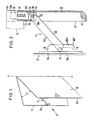
- a sash which is generally designated 10 and a frame, which is generally designated 12.
- the two frame legs of the casement frame and the frame, which are remote from the axis of rotation, are designated by 10a and 12a, respectively.
- a device 14 is provided between the frame legs 10a and 12a for fixing the casement 10 relative to the frame 12, which allows a predetermined opening angle ⁇ to be set about the axis of rotation A-A.
- FIG. 2 more details on FIG. 1 can be seen.
- a fitting plate 16 on the outer frame side, which carries a rib with a fork-like open sliding slot 18.
- a housing 20 of approximately square cross section is fastened to the sash frame, specifically on the rollover peripheral surface 10b of the sash frame leg 10a.
- This housing 20 has an opening 22 in its side wall 24 facing the frame leg 12a.
- a slider 26 is slidably disposed in the housing 20, a slider 26 is slidably disposed.
- the slider 26 In its uppermost position and can be pushed down from the basic position against the action of a helical compression spring.
- a flap 30 is articulated on the slide 26 by means of a swivel joint 32.
- the 5, consists of two lamellae 30a and 30b, which are supported on both sides of a downward extension tongue 26b of the slider 26 by stub shafts 32a, 32b on the slider 26.
- the stub shafts 32a and 32b together form the swivel joint 32.
- the two slats 30a, 30b of the flap 30 are connected to one another by a slot engagement bolt 34 which engages in the fork-like open slot 18, the two slats 30a and 30b in FIG 2 are located on both sides of the rib 16.
- the sash frame 10 is fixed relative to the frame 12 in that, on the one hand, the slot engagement bolt 34 engages in the fork-like slot 18 and, on the other hand, the opening pocket 30 is immobilized in relation to the housing 20.
- a cam 36 is attached to the lamella 30b (the same applies to the lamella 30a) and has a disengagement curve 36a and a latching catch 36b.
- a cam engaging edge 38 which defines the upper end of the opening 22 in the side wall 24 is in engagement with the latch 36b.
- the disengagement curve 36a rolls off at the cam engagement edge 38, with the slide 26 initially being pulled down against the action of the helical compression spring 28 compared to the basic position according to FIG. 3, until Finally, the cam engagement edge 38 can fall into the latch 36b of the cam 36 and thus roll the slider 26 back into the basic position, whereby the setting according to FIG. 2 is reached again.
- FIG. 4 shows a through-bore 40 of the housing at the lower end of the housing 20 and a hollow rivet 42 penetrating the housing 20 at the upper end of the housing.
- the through-bore 40 and the hollow rivet 42 are intended for receiving fastening screws, with which the housing 20 is attached to the rollover peripheral surface 10b.
- the hollow rivet 42 passes through an elongated hole 44 in the slider 26.
- a bore 46 is made in the upper end of the slider 26 and is closed by a plug 48.
- the helical compression spring 28 is accommodated, which is supported at one end against a shoulder surface of the stopper 48 and at the other end against the rivet 42. In this way, the helical compression spring 28 looks for the slide 26 upwards slide into the position shown in Figs. 2 and 3. 4 and 5, however, the slider 26 is pressed against the action of the helical compression spring 28 down.
- a slope 16b is attached to the lower end of the rib 16a of the fitting part 16. 3 assumes its uppermost position, the slot engaging bolt 34 is at the height of the bevel 16b. This means that by pressing the casement 10 against the frame 12, the slot engaging bolt 34 can be brought into engagement with the bevel 16b. This also means that the slot engaging pin 34 exerts a pull on the deployment pocket 30 and on the slide 26, so that the slide 26 is pulled down with the deployment pocket 30 and the slot engagement bolt 34 engages in the sliding slot 18. After latching, the slider 26, the pop-out pocket 30 and the slot engagement bolt 34 return to the position shown in FIG. 3.
Abstract
Description
Die Erfindung betrifft eine Einrichtung zur Feststellung eines um eine Drehachse drehbaren Flügelrahmens an einem Blendrahmen in einer vorbestimmten Drehöffnungsstellung bei einer Tür, einem Fenster oder dergleichen, umfassend
eine Ausstellasche, welche mit einem Ende an einem ersten von zwei zusammengehörigen Rahmenschenkeln des Flügelrahmens und des Blendrahmens durch ein Schwenkgelenk angelenkt ist und an ihrem anderen Ende mit dem zweiten dieser zusammengehörigen Rahmenschenkel durch ein Schwenkschiebegelenk mit einem gabelartigen Schliebeschlitz verbunden ist,
Verrastungsmittel, welche die Einstellung der Ausstelllasche gegenüber den Rahmenschenkeln bei Eintritt des aus der Schließstellung kommenden Flügelrahmens in die vorbestimmte Drehöffnungsstellung selbsttätig immobilisieren,
und handbetätigte Lösemittel für diese Verrastungsmittel.The invention relates to a device for determining a sash frame rotatable about an axis of rotation on a frame in a predetermined rotational opening position for a door, a window or the like, comprising
a display pocket which is articulated at one end to a first of two associated frame legs of the casement frame and the frame by a swivel joint and at its other end to the second of these associated frame legs by a swivel sliding joint with a fork-like slit,
Latching means which automatically immobilize the setting of the flap with respect to the frame legs when the sash frame coming from the closed position enters the predetermined rotational opening position,
and hand-operated solvents for these latching means.
Eine solche Einrichtung ist aus der deutschen Gebrauchsmusterschrift 84 17 729 bekannt.Such a device is known from German utility model 84 17 729.
Bei der bekannten Anordnung ist eine Öffnung des Flügelrahmens nur bis zu der vorbestimmten Drehöffnungsstellung möglich. Eine darüber hinausgehende Öffnung des Flügelrahmens ist jedenfalls für den Laien, d. h. für den Bewohner der mit dem Fenster ausgerüsteten Wohnung nicht ohne weiteres möglich.In the known arrangement, an opening of the casement is only possible up to the predetermined opening position. A further opening of the casement is in any case for the layperson, i. H. not easily possible for the resident of the apartment equipped with the window.
Der Erfindung liegt die Aufgabe zugrunde, eine Einrichtung der oben bezeichneten Art zu schaffen, bei der durch einfache Umstellmaßnahmen auch eine Öffnung des Flügelrahmens in eine weitere Drehöffnungsstellung, insbesondere in eine voll geöffnete Stellung möglich ist.The invention has for its object to provide a device of the type described above, in which an opening of the casement into a further rotational opening position, in particular in a fully open position, is possible by simple conversion measures.
Zur Lösung dieser Aufgabe wird erfindungsgemäß vorgeschlagen,
daß das Schwenkgelenk an einem in Längsrichtung des ersten Rahmenschenkels in einer Gleitstückführung beweglichen Gleitstück angeordnet ist,
daß dieses Gleitstück durch Federmittel in Richtung auf eine Grundstellung vorgespannt ist
daß das Schwenkschiebegelenk in der Schließstellung des Flügelrahmens dadurch auskuppelbar ist, daß durch Ausrücken des Gleitstücks aus seiner Grundstellung entgegen der Wirkung der Federmittel die Ausstellasche gegenüber dem gabelartigen Schiebeschlitz verschoben wird.To solve this problem, the invention proposes
that the swivel joint is arranged on a sliding piece that is movable in the longitudinal direction of the first frame leg in a sliding piece guide,
that this slider is biased by spring means towards a basic position
that the swivel sliding joint in the closed position of the casement can be uncoupled in that, by disengaging the slider from its basic position against the action of the spring means, the flap is moved relative to the fork-like sliding slot.
Die erfindungsgemäße Einrichtung kann an den verschiedensten Typen von Fenstern angebracht werden, insbesondere einfachen Drehfenstern mit vertikaler Drehachse, Kippfenstern mit horizontaler Kippachse, Drehkippfenstern mit horizontaler Kippachse und vertikaler Drehachse und Schwingfenstern mit horizontaler Schwingachse. In allen Fällen kann die Einrichtung so angeordnet werden, daß die Achsen des Schwenkgelenks und des Schwenkschiebegelenks parallel zu der jeweiligen Drehachse bzw. Kippachse, bzw. Schwingachse sind, aber auch so, daß die Achsen des Schwenkgelenks und des Schwenkschiebegelenks im wesentlichen senkrecht zu der Drehachse bzw. Kippachse, bzw. Schwingachse des Flügelrahmens sind.The device according to the invention can be attached to a wide variety of types of windows, in particular simple rotating windows with a vertical rotating axis, tilting windows with a horizontal tilting axis, rotating tilting windows with a horizontal tilting axis and vertical rotating axis and swinging windows with a horizontal swinging axis. In all cases, the device can be arranged so that the axes of the swivel joint and the swivel sliding joint are parallel to the respective axis of rotation or tilting axis or swinging axis, but also such that the axes of the swivel joint and the pivoting sliding joint are substantially perpendicular to the axis of rotation or tilting axis or swinging axis of the casement.
Eine bevorzugte Ausführungsform sieht vor,
daß die Verrastungsmittel durch einen an der Ausstelllasche angeordneten Ausrück- und Verrastungsnocken einerseits und eine mit diesem Ausrück- und Verrastungsnocken zusammenwirkende Nockeneingriffskante an der Gleitstückführung andererseits gebildet sind, wobei bei der durch das Annähern des Flügelrahmens an die vorbestimmte Drehöffnugsstellung bewirkten Schwenkbewegung der Ausstelllasche um das Schwenkgelenk durch das Zusammenwirken des Ausrück- und Verrastungsnocken und der Nockeneingriffskante zunächst ein Ausrücken des Gleitstücks aus der Grundstellung entgegen der Wirkung der Federmittel bewirkt wird und erst bei Erreichen der vorbestimmten Drehöffnungsstellung Nocken und Nockeneingriffskante unter der Wirkung der durch die Federmittel erzwungenen Rückkehr des Gleitstücks in Richtung Grundstellung in gegenseitige Verrastung einfallen.A preferred embodiment provides
that the latching means are formed by a disengagement and latching cam arranged on the flap on the one hand and a cam engaging edge cooperating with this disengaging and latching cam on the slide guide on the other hand, with the pivoting movement of the flap around the swivel joint caused by the sash frame approaching the predetermined rotational opening position the interaction of the disengaging and latching cam and the cam engaging edge initially causes the slider to disengage from the basic position against the action of the spring means and only when the predetermined rotary opening position reaches the cam and cam engaging edge under the effect of the spring means returning the slider towards the basic position engage in mutual locking.
Dabei kann die Verrastung durch von Hand ausgelöstes Verschieben des Gleitstücks aus der Grundstellung entgegen der Wirkung der Federmittel lösbar sein.In this case, the locking can be released by moving the slider from the basic position by hand, counter to the action of the spring means.
Der Ausrück- und Verrastungsnocken kann mit einer Ausrückkurve und angrenzend an die Ausrückkurve einer Rastfalle ausgeführt werden, wobei die Ausrückkurve beim Überführen des Flügelrahmens in die vorbestimmte Drehöffnungsstellung im Zusammenwirken mit der Nockeneingriffskante das Ausrücken des Gleitstücks aus der Grundstellung entgegen der Wirkung der Federmittel bewirkt und die Rastfalle beim Erreichen der vorbestimmten Drehöffnungsstellung die Nockeneingriffskante aufnimmt und damit die Ausstellasche immobilisiert.The disengagement and latching cam can be carried out with a disengagement curve and adjacent to the disengagement curve of a latching trap, the disengagement curve when the sash is brought into the predetermined rotational opening position in cooperation with the cam engagement edge, which disengages the slider from the basic position against the action of the spring means and that When the predetermined rotary opening position is reached, the catch engaging edge picks up and the immobilization pocket is thus immobilized.
Eine einfache Ausführungsform für das Schwenkschiebegelenk besteht aus einem gabelartig offenen Schiebeschlitz eines am zweiten Rahmenschenkel befestigten Beschlagteils einerseits und eines Schlitzeingriffsbolzens am anderen, d. h. gegenüber dem ersten Rahmenschenkel frei beweglichen Ende der Ausstellasche andererseits. Dabei kann der Schlitzeingriffsbolzen aus dem offenen Gabelende austreten, wenn das Gleitstück entgegen der Wirkung der Federmittel durch Handeinwirkung aus der Grundstellung ausgerückt wird.A simple embodiment for the swivel sliding joint consists of a fork-like open sliding slot of a fitting part fastened to the second frame leg on the one hand and a slot engagement bolt on the other, i. H. compared to the first frame leg freely movable end of the display pocket on the other hand. The slot engaging bolt can emerge from the open fork end if the slide is moved out of the basic position by hand against the action of the spring means.
Eine in ihrem Aufbau einfache und in ihrem Raumbedarf akzeptable Ausführungsform für die Ausstellasche besteht darin, daß zwei zueinander parallele Lamellen die Ausstellasche bilden, wobei diese Lamellen an dem einen Ende der Ausstellasche das Gleitstück zwischen sich aufnehmen und an dem anderen Ende Schlitzeingriffsbolzen verbunden sind. Dabei kann eine den Schiebeschlitz aufweisende Rippe des am zweiten Rahmenschenkel angebrachten Beschlagteils zwischen die beiden Lamellen eingreifen.An embodiment of the display pocket which is simple in construction and acceptable in terms of its space requirement consists in that two mutually parallel slats form the display pocket, these slats receiving the slider between them at one end of the display pocket and slot engaging bolts are connected at the other end. In this case, a rib having the sliding slot of the fitting part attached to the second frame leg can engage between the two slats.
Das Gleitstück kann an seinem von der Ausstellasche abgelegenen Ende als handbetätigbare Lösetaste ausgebildet sein. Diese Lösetaste steht zur Verfügung einmal, um in der verrasteten vorbestimmten Öffnungsstellung des Flügelrahmens die Verrastung wieder zu lösen, zum anderen aber auch um bei in Schließstellung befindlichem Flügelrahmen eine Vollöffnung des Flügelrahmens, d. h. eine Öffnung über die vorbestimmte Öffnungsstellung hinaus zu ermöglichen. Hierin liegt eine besondere Vereinfachung insofern, als für zwei verschiedene Funktionen ein und dasselbe Handbetätigungsorgan zur Verfügung steht.At its end remote from the display pocket, the slider can be designed as a manually operable release button. This release button is available on the one hand to release the catch again in the locked predetermined open position of the casement, but on the other hand also to fully open the casement when the casement is in the closed position. H. to enable an opening beyond the predetermined opening position. This is a particular simplification in that one and the same manual actuator is available for two different functions.
Um eine stabile und ästhetisch ansprechende Gestaltung zu erhalten wird vorgeschlagen, daß die Gleitstückführung ein im Querschnitt rechteckiges, längliches Gehäuse umfaßt, welches in der Schließstellung des Flügelrahmens die Ausstellasche auf ihrer ganzen Länge aufnimmt und in einer Längsseitenwand eine Öffnung für den Durchtritt der Ausstellasche aufweist. Das längliche Gehäuse dient dann nur auf einem Teil seiner Länge als Gleitstückführung und auf dem Rest seiner Länge zur Verdeckung und gegebenenfalls Stützung der Ausstellasche. Dabei kann eine dem Gleitstück nahe Endkante der Öffnung als Nockeneingriffskante ausgebildet sein.In order to obtain a stable and aesthetically pleasing design, it is proposed that the slide guide comprises a rectangular, elongated housing which in the closed position of the casement receives the entire length of the opening pocket and has an opening in the longitudinal side wall for the opening of the opening pocket. The elongated housing then serves only as part of its length as a slide guide and on the rest of its length for covering and, if necessary, supporting the flap. In this case, an end edge of the opening close to the slider can be designed as a cam engagement edge.
Um den Flügelrahmen in der vorbestimmten Öffnungsstellung und/oder in der Schließstellung sperren und gegen unbeabsichtigtes Öffnen von innen und/oder von außen sichern zu können, wird vorgeschlagen, daß das Gleitstück in seiner Grundstellung gegenüber der Gleitstückführung sperrbar ist. Dabei kann die Ausstellasche in der Grundstellung des Gleitstücks entweder eine Parallelstellung zum zugehörigen ersten Rahmenschenkel entsprechend der Schließstellung des Flügelrahmens einnehmen und durch Zusammenwirken der Ausrückkurve mit der Nockeneingriffskante in dieser Parallelstellung festgelegt sein oder die Ausstellasche ist in der vorbestimmten Drehöffnungsstellung des Flügelrahmens durch Zusammenwirken der Rastfalle mit der Nockeneingriffskante immobilisiert. Eine solche Sperrung dient beispielsweise der Sicherung gegen unbeabsichtigtes Öffnen des Flügelrahmens durch Kinder.In order to lock the sash frame in the predetermined open position and / or in the closed position and to be able to secure it against unintentional opening from the inside and / or from the outside, it is proposed that the slider can be locked in its basic position relative to the slider guide. The display pocket in the basic position of the slider can either assume a parallel position to the associated first frame leg corresponding to the closed position of the casement and can be fixed in this parallel position by the interaction of the disengagement curve with the cam engaging edge, or the display pocket can be in the predetermined rotational opening position of the casement by cooperation of the latch the cam engaging edge is immobilized. Such a lock is used, for example, to prevent children from accidentally opening the casement.
Die Sperrung kann z. B. durch eine Madenschraube in dem Gleitstück gebildet sein, insbesondere eine solche mit Imbus, welche in Eingriff mit einer korrespondierenden Öffnung in der Gleitstückführung verschraubbar ist.The block can e.g. B. be formed by a grub screw in the slider, especially one with an Allen key, which can be screwed into engagement with a corresponding opening in the slider guide.
Im Hinblick auf Rechts- und Linksverwendbarkeit der Einrichtung, wird vorgeschlagen, daß sie in bezug auf eine zu den Achsen des Schwenk- und des Schwenkschiebegelenks senkrechte Symmetrieebene symmetrisch ausgebildet ist.With regard to the right and left usability of the device, it is proposed that it be designed symmetrically with respect to a plane of symmetry perpendicular to the axes of the pivoting and pivoting sliding joints.
Im Hinblick auf einen einfachen Lösezugriff in der vorbestimmen Drehöffnungsstellung ist es vorteilhaft, wenn die Gleitstückführung an einem Flügelrahmenschenkel befestigbar ist. Es ist aber durchaus möglich,die Gleitstückführung auch an einem Blendrahmenschenkel zu befestigen.With regard to a simple release access in the predetermined rotary opening position, it is advantageous if the slide guide can be fastened to a casement leg. However, it is also possible to attach the slide guide to a frame leg.
Die erfindungsgemäße Einrichtung ist, da sie unabhängig von sonstigen Teilen eines Beschlagsystems ist, insbesondere auch zur Nachrüstung, d. h. zum nachträglichen Anbau an einem Fenster oder an einer Tür geeignet.The device according to the invention is, in particular, independent of other parts of a fitting system also suitable for retrofitting, ie for retrofitting to a window or door.
Zur Ausschaltung von Befestigungsschwierigkeiten für die Gleitführung im Bereich des Gleitstücks wird vorgeschlagen, daß zur Führung des Gleitstücks und/oder zur Bewegungsbeschränkung des Gleitstücks und/oder zur Federmittelabstützung eine die Gleitstückführung und das Gleitstück durchsetzender Hohlniet vorgesehen ist, welcher eine Befestigungsschraube zur Befestigung der Gleitstückführung an dem jeweiligen Rahmenschenkel aufnimmt. Auf diese Weise werden mindestens zwei Funktionen durch ein und dasselbe Teil, nämlich den Hohlniet erfüllt.To eliminate mounting difficulties for the slide guide in the area of the slide, it is proposed that a rivet penetrating the slide guide and the slide is provided to guide the slide and / or to restrict movement of the slide and / or to support the spring means, which rivet has a fastening screw for fastening the slide guide the respective frame leg. In this way, at least two functions are performed by one and the same part, namely the hollow rivet.
Wenn die Einrichtung so angebracht wird, daß die Achsen des Schwenkgelenks und des Schwenkschiebegelenks parallel zur jeweiligen Drehachse sind, so läßt sich durch Veränderung des Orts der Einrichtung längs der Rahmenschenkel die Ausstellöffnungsweite ohne sonstige Veränderung der Einrichtung variieren.If the device is attached so that the axes of the swivel joint and the swivel sliding joint are parallel to the respective axis of rotation, the opening opening width can be varied without changing the device by changing the location of the device along the frame legs.
Es ist möglich, daß an einem den Schiebeschlitz aufnehmenden Beschlagteil angrenzend an das offene Ende des Schiebeschlitzes eine Schrägkante vorgesehen ist, welche bei in Grundstellung befindlichem Gleitstück im Bereich des Schlitzeingriffsbolzens liegt. Dadurch wird das Schließen des Flügelrahmens erleichtert. Es ist zum Schließen nicht erforderlich, eine Handeinwirkung auf das Gleitstück vorzunehmen.It is possible that a sloping edge is provided on a fitting part receiving the sliding slot adjacent to the open end of the sliding slot, which is in the area of the slot engagement bolt when the slide is in the basic position. This will make it easier to close the casement. It is not necessary to operate the slide manually to close it.
Die beiliegenden Figuren erläutern die Erfindung anhand eines Ausführungsbeispiels. Es stellen dar:
- Fig. 1
- schematisch ein Drehfenster mit einer erfindugsgemäßen Einrichtung;
- Fig. 2
- eine Ansicht auf die Ausstelleinrichtung in Pfeilrichtung II der Fig. 1, und zwar teilweise geschnitten entsprechend Linie IV-IV der Fig. 5;
- Fig. 3
- eine Ansicht entsprechend derjenigen der Fig. 2 bei in Schließstellung befindlichem Flügelrahmen;
- Fig. 4
- eine Ansicht entsprechend derjenigen der Fig. 3 bei nach unten gedrücktem Gleitstück zur Vorbereitung einer Vollöffnung des Flügelrahmens und
- Fig. 5
- einen Schnitt nach Linie V-V der Fig. 4.
- Fig. 1
- schematically a rotating window with a device according to the invention;
- Fig. 2
- a view of the opening device in the direction of arrow II of Figure 1, partially cut along line IV-IV of Fig. 5.
- Fig. 3
- a view corresponding to that of Figure 2 in the closed position sash.
- Fig. 4
- a view corresponding to that of FIG. 3 with the slider pressed down to prepare a full opening of the casement and
- Fig. 5
- a section along line VV of Fig. 4th
In Fig. 1 erkennt man einen Flügelrahmen, der ganz allgemein mit 10 bezeichnet ist und einen Blendrahmen, der ganz allgemein mit 12 bezeichnet ist. Die beiden von der Drehachse abgelegenen Rahmenschenkel des Flügelrahmens und des Blendrahmens sind mit 10a bzw. 12a bezeichnet. Zwischen den Rahmenschenkeln 10a und 12a ist eine Einrichtung 14 zur Feststellung des Flügelrahmens 10 gegenüber dem Blendrahmen 12 vorgesehen, die einen vorbestimmten Öffnungswinkel α um die Drehachse A-A einzustellen gestattet.In Fig. 1 you can see a sash, which is generally designated 10 and a frame, which is generally designated 12. The two frame legs of the casement frame and the frame, which are remote from the axis of rotation, are designated by 10a and 12a, respectively. Between the
Gemäß Fig. 2 erkennt man nähere Einzelheiten zu Fig. 1. An der Blendrahmensichtfläche 12b des Flügelrahmenschenkels 12a ist eine blendrahmenseitige Beschlagplatte 16 angebracht, welche eine Rippe mit einem gabelartig offenen Schiebeschlitz 18 trägt.According to FIG. 2, more details on FIG. 1 can be seen. On the outer frame
An dem Flügelrahmen, und zwar an der Überschlagumfangsfläche 10b des Flügelrahmenschenkels 10a ist ein Gehäuse 20 von annähernd quadratischem Querschnitt befestigt. Dieses Gehäuse 20 besitzt eine Öffnung 22 in ihrer den Blendrahmenschenkel 12a zugekehrten Seitenwand 24.A
In dem Gehäuse 20 ist ein Gleitstück 26 verschiebbar angeordnet. In Fig. 2 befindet sich das Gleitstück 26 in seiner obersten Stellung und kann gegen die Wirkung einer Schraubendruckfeder aus der Grundstellung nach unten geschoben werden. An dem Gleitstück 26 ist eine Ausstelllasche 30 mittels eines Schwenkgelenks 32 angelenkt. Die Ausstellasche 30 besteht, wie aus Fig. 5 zu ersehen, aus zwei Lamellen 30a und 30b, die beiderseits einer nach unten gerichteten Verlängerungszunge 26b des Gleitstücks 26 durch Stummelwellen 32a, 32b an dem Gleitstück 26 gelagert sind. Die Stummelwellen 32a und 32b bilden zusammen das Schwenkgelenk 32. An ihrem anderen Ende sind die beiden Lamellen 30a, 30b der Ausstellasche 30 durch einen Schlitzeingriffsbolzen 34 miteinander verbunden, der in den gabelartig offenen Schlitz 18 eingreift, wobei die beiden Lamellen 30a und 30b in Fig. 2 beidseits der Rippe 16 gelegen sind. In Fig. 2 ist der Flügelrahmen 10 gegenüber dem Blendrahmen 12 dadurch festgelegt, daß einerseits der Schlitzeingriffbolzen 34 in den gabelartigen Schlitz 18 eingreift und zum anderen die Ausstellasche 30 gegenüber dem Gehäuse 20 immobilisiert ist. An der Lamelle 30b (das gleiche gilt für die Lamelle 30a) ist ein Nocken 36 angebracht, der eine Ausrückkurve 36a und eine Rastfalle 36b aufweist. In der Fig. 2 ist eine Nockeneingriffskante 38, welche das obere Ende der Öffnung 22 in der Seitenwand 24 begrenzt, in Eingriff mit der Rastfalle 36b. Solange das Gleitstück 26 unter der Wirkung der Schaubendruckfeder 28 die in Fig. 2 eingestellte Grundstellung einnimmt, kann die Ausstellasche 30 gegenüber dem Gehäuse 20 nicht verschwenkt werden. Dies ist der Grund für die Immobilisierung des Flügelrahmens 10 gegenüber dem Blendrahmen 12.In the
Wenn man den Flügelrahmen ausgehend von der vorbestimmten Drehöffnungsstellung α gemäß den Fig. 1 und 2 in Schließstellung überführen will, so bracht man nur auf das Gleitstück 26 zu drücken, dessen oberes Ende 26a als Drucktaste ausgebildet ist, solange, bis der Nocken 36 mit seiner Ausrückkurve 36a bis unter die Nockeneingriffskante 38 getreten ist, so daß die Ausstellasche 30 fortan im Gegenzeigersinn gemäß Fig. 2 verschwenkt werden kann. Wenn dann der Flügelrahmen 10 an den Blendrahmen 12 angenähert wird, so führt die Schwenklasche 30 eine Drehung im Gegenzeigersinn um das Schwenkgelenk 32 aus. Bereits nach geringfügiger solcher Drehung kann der Druck auf die Drucktaste 26a aufhören, weil dann die Ausrückkurve 36a in Eingriff mit der Nockeneingriffskante 38 getreten ist. Bei zunehmender Annäherung des Flügelrahmens 10 an den Blendrahmen 12 gleitet die Ausrückkurve 36a an der Nockeneingriffskante 38, wobei die Stellung der Fig. 3 erreicht wird. In dieser Stellung gemäß Fig. 3 ist das Gleitstück 26 dank der Form der Ausrückkurve 36a wieder in der Grundstellung angelangt (siehe Fig. 3). In Fig. 3 erkennt man, daß in der Schließstellung des Flügelrahmens der Schlitzeingriffsbolzen 34 immer noch in den gabelartig offenen Schiebeschlitz 18 eingreift, so daß bei erneuter Öffnung des Flügelrahmens gegenüber dem Blendrahmen in Richtung auf die in Fig. 1 und 2 dargestellte vorbestimmte Drehöffnungsstellung nach wie vor die Bereitschaft zur Verrastung in der vorbestimmten Drehöffnungsstellung besteht. Bei dem erneuten Übergang in die vorbestimmte Drehöffnungsstellung nach den Fig. 1 u 2 wälzt sich die Ausrückkurve 36a an der Nockeneingriffskante 38 ab, wobei gegenüber der Grundstellung gemäß Fig. 3 das Gleitstück 26 zunächst gegen die Wirkung der Schraubendruckfeder 28 nach unten gezogen wird, bis schließlich die Nockeneingriffskante 38 in die Rastfalle 36b des Nockens 36 einfallen kann und damit das Gleitstück 26 wieder in die Grundstellung zurückwälzt, wodurch die Einstellung gemäß Fig. 2 wieder erreicht ist.If you want to move the sash starting from the predetermined rotational opening position α according to FIGS. 1 and 2 in the closed position, you only need to press on the
Wenn beabsichtigt ist, das Fenster über die in Fig. 1 dargestellte vorbestimmte Drehöffnungsstellung α hinaus zu öffnen, so ist dies möglich, indem man vor Beginn der Drehöffnung des in Schließstellung befindlichen Flügelrahmens das Gleitstück 26 aus der Stellung gemäß Fig. 3 in die Stellung gemäß Fig. 4 nach unten drückt. Wenn man nun die Drehöffnung des Flügelrahmens beginnt, so kann der Schlitzeingriffsbolzen 34 aus dem Schiebeschlitz 18 seitlich austreten, so daß das Schiebegelenk 34,18 entkuppelt ist.If intended, the window over that shown in Fig. 1 To open the predetermined rotational opening position α, this is possible by pressing the
In Fig. 4 erkennt man am unteren Ende des Gehäuses 20 eine Durchgangsbohrung 40 des Gehäuses und in Fig. 5 am oberen Ende des Gehäuses einen das Gehäuse 20 durchsetzenden Hohlniet 42. Die Durchgangsbohrung 40 und der Hohlniet 42 sind zur Aufnahme von Befestigungsschrauben bestimmt, mit denen das Gehäuse 20 an der Überschlagumfangsfläche 10b befestigt wird. Der Hohlniet 42 durchsetzt ein Langloch 44 des Gleitstücks 26. In das obere Ende des Gleitstücks 26 ist eine Bohrung 46 eingebracht, die durch einen Stopfen 48 verschlossen ist. Zwischen dem Stopfen 48 und der Bohrung 46 ist die Schraubendruckfeder 28 untergebracht, die sich mit ihrem einen Ende gegen eine Schulterfläche des Stopfens 48 abstützt und mit ihrem anderen Ende gegen den Hohlniet 42. Auf diese Weise sucht die Schraubendruckfeder 28 das Gleitstück 26 nach oben zu schieben in die in den Fig. 2 und 3 gezeigte Stellung. In Fig. 4 und 5 ist dagegen das Gleitstück 26 gegen die Wirkung der Schraubendruckfeder 28 nach unten gedrückt.4 shows a through-
In der in den Fig. 2 und 3 gezeigten Grundstellung des Gleitstücks 26 befindet sich eine innerhalb des Gleitstücks 26 aufgenommene Madenschraube 50 mit Imbuskopf in Flucht mit einem Loch 52 des Gehäuses 20. Die Madenschraube kann mit einem Imbusschlüssel so weit herausgedreht werden, daß ihr äußeres Ende in das Loch 52 eingreift. Dann ist eine Verschiebung des Gleitstücks 26 aus der Grundstellung heraus nicht mehr möglich. Dies bedeutet, daß sowohl der Zustand gemäß Fig. 2 (Flügelrahnen in vorbestimmter Drehöffnungsstllung α ) als auch der Zustand gemäß Fig. 3 (Flügelrahmen in Schließstellung) willkürlich gesperrt werden kann.In the basic position of the
Aus den Fig. 2 und 3 erkennt man, daß am unteren Ende der Rippe 16a des Beschlagteils 16 eine Schräge 16b angebracht ist. Wenn das Gleitstück 26 gemäß Fig. 3 seine oberste Stellung einnimmt, dann befindet sich der Schlitzeingriffsbolzen 34 auf der Höhe der Schräge 16b. Dies bedeutet, daß durch Andrücken des Flügelrahmens 10 gegen den Blendrahmen 12 der Schlitzeingriffsbolzen 34 in Eingriff mit der Schräge 16b gebracht werden kann. Dies bedeutet weiter, daß der Schlitzeingriffsbolzen 34 einen Zug auf die Ausstellasche 30 und auf das Gleitstück 26 ausübt, so daß das Gleitstück 26 mit der Ausstellasche 30 nach unten gezogen wird und der Schlitzeingriffsbolzen 34 in den Schiebeschlitz 18 einrastet. Nach erfolgter Einrastung kehren das Gleitstück 26, die Ausstellasche 30 und der Schlitzeingriffsbolzen 34 wieder in die in Fig. 3 gezeigte Stellung zurück.From Figs. 2 and 3 it can be seen that a
Claims (18)
- A device for fixing a casement or leaf (10) swivellable about a swivel axis (A-A) to a window or door frame (12) in a predetermined swivel open position α, comprising
a hook-out bracket (30), which is articulated with one end to the first (10a) of two associated vertical frame members (10a, 12a) of the casement or leaf (10) and the frame (12) by a swivel hinge (32) and is connected at its other end with the second (12a) of these associated vertical frame members (10a, 12a) by a swinging/sliding hinge (18, 34) with a fork-type slide slot (18),
arresting means (36, 38), which automatically immobilize the setting of the hook-out bracket (30) with respect to the vertical frame members (10a, 12a) upon entry of the casement or leaf (10) coming from the closed position into the predetermined swivel open position α,
and hand-operated loosening means (26a) for these arresting means (36b, 38),
characterized in that
the swivel hinge (32) is arranged on a sliding member (26) movable in a sliding member guide (20) in the longitudinal direction of the first vertical frame member (10a),
this sliding member (26) is biased by spring means (28) in the direction of a normal position,
the swinging/sliding hinge (18, 34) can be uncoupled in the closed position of the casement or leaf (10) in that, by displacement of the sliding member (26) out of its normal position against the action of the spring means (28), the hook-out bracket (30) is displaced with respect to the fork-type slide slot (18). - A device according to claim 1, characterized in that the arresting means (36b, 38) is formed by a displacement and arresting cam (36) arranged on the hook-out bracket (30) on the one hand and a cam engagement edge (38) on the sliding member guide (20) and interacting with this displacement and arresting cam on the other hand, displacement of the sliding member (26) from the normal position against the action of the spring means (28) being effected first of all by the interaction of the displacement and arresting cam (36) and cam engagement edge (38) at the time of the swivel movement of the hook-out bracket (30) about the swivel hinge (32) caused by the approach of the casement or leaf (10) towards the predetermined swivel open position α, the displacement and arresting cam (36) and cam engagement edge (38) falling into mutual arresting engagement only upon reaching the predetermined swivel open position α under the effect of the return of the sliding member (26) in the direction of the normal position caused by the spring means (28).
- A device according to claim 1 or claim 2, characterized in that arresting engagement can be loosened by hand-triggered displacement of the sliding member (26) out of the normal position against the action of the spring means (28).
- A device according to claim 2 or claim 3, characterized in that the displacement and arresting cam (36) comprises a displacement curve (36a) and a catch (36b) adjoining the displacement curve (36a).
- A device according to any one of claims 1 to 4, characterized in that the swinging/sliding hinge (18, 34) consists of a fork-type open slide slot (18) in a piece of door or window furniture (16) attached to the second vertical frame member (12a) and a slot engagement bolt (34) at the other end of the hook-out bracket (30).
- A device according to claim 5, characterized in that the hook-out bracket (30) consists of two mutually parallel plates (30a, 30b) which accommodate the sliding member (26) between them at one end and are connected at the other end by the slot engagement bolt (34), a rib (16), comprising the sliding slot (18), of the piece of furniture (16) attached to the second vertical frame member engaging between the two plates (30a, 30b).
- A device according to any one of claims 1 to 6, characterized in that the sliding member (26) is constructed at its end remote from the hook-out bracket (30) as a hand-operable release key (26a).
- A device according to any one of claims 1 to 7, characterized in that the sliding member guide comprises a cross-sectionally rectangular, elongate housing (20), which accommodates the whole length of the hook-out bracket (30) in the closed position of the casement or leaf (10) and comprises an opening (22) in a longitudinal side wall (24) for the passage of the hook-out bracket (30).
- A device according to claim 8, characterized in that an end edge (38) of the opening (22) near the sliding member (26) is constructed as a cam engagement edge.
- A device according to any one of claims 1 to 9, characterized in that the sliding member (26) is blockable in its normal position with respect to the sliding member guide (20).
- A device according to claim 10, characterized in that a grub screw (50), especially one with a hexagonal socket, is provided in the sliding member (26), which grub screw (50) can be screwed into engagement with a corresponding opening (52) in the sliding member guide (20).
- A device according to any one of claims 1 to 10, characterized in that it is constructed symmetrically in relation to a plane of symmetry perpendicular to the axes of the swivel and swinging/sliding hinges (32 and 18, 34 respectively).
- A device according to any one of claims 1 to 12, characterized in that the sliding member guide (20) can be attached to a vertical casement or leaf member (10a).
- A device according to any one of claims 1 to 13, characterized in that it is constructed for later mounting an an already furnished window, door or the like.
- A device according to any one of claims 1 to 14, characterized in that a hollow rivet (42) passing through the sliding member guide (20) and the sliding member (26) is provided to guide the sliding member (26) and/or to restrict the movement of the sliding member (26) and/or to support the spring means, which hollow rivet (42) accommodates a fastening screw for fastening the sliding member guide to the respective vertical frame member.
- A device according to any one of claims 1 to 15, characterized in that the predetermined swivel open position α is an intermediate position between the closed position of the casement or leaf (10) and a fully open position of the casement or leaf (10).
- A device according to any one of claims 1 to 16, characterized in that it can be brought into various positions along the associated vertical frame member (10a, 12a).
- A device according to any one of claims 1 to 17, characterized in that a sloping edge (16b) is provided on a piece of door or window furniture (16) comprising the slide slot (18), which sloping edge (16b) adjoins the open end of the slide slot (18) and lies, when the sliding member (26) is in the normal position, in the area of a slot engagement bolt (34).
Priority Applications (1)
| Application Number | Priority Date | Filing Date | Title |
|---|---|---|---|
| AT86106655T ATE66043T1 (en) | 1985-06-14 | 1986-05-15 | DEVICE FOR FIXING A WINCH FRAME ROTATABLE ABOUT A ROTATIONAL AXIS ON A DISC FRAME. |
Applications Claiming Priority (2)
| Application Number | Priority Date | Filing Date | Title |
|---|---|---|---|
| DE3521492 | 1985-06-14 | ||
| DE19853521492 DE3521492A1 (en) | 1985-06-14 | 1985-06-14 | DEVICE FOR DETECTING A BLADE FRAME WHICH CAN BE TURNED BY A ROTARY AXIS ON A FRAME |
Publications (3)
| Publication Number | Publication Date |
|---|---|
| EP0204991A2 EP0204991A2 (en) | 1986-12-17 |
| EP0204991A3 EP0204991A3 (en) | 1987-06-24 |
| EP0204991B1 true EP0204991B1 (en) | 1991-08-07 |
Family
ID=6273365
Family Applications (1)
| Application Number | Title | Priority Date | Filing Date |
|---|---|---|---|
| EP86106655A Expired - Lifetime EP0204991B1 (en) | 1985-06-14 | 1986-05-15 | Holding device for a wing frame swivelling around an axis with respect to an outer frame |
Country Status (5)
| Country | Link |
|---|---|
| US (1) | US4691950A (en) |
| EP (1) | EP0204991B1 (en) |
| AT (1) | ATE66043T1 (en) |
| DE (2) | DE3521492A1 (en) |
| DK (1) | DK164710C (en) |
Families Citing this family (13)
| Publication number | Priority date | Publication date | Assignee | Title |
|---|---|---|---|---|
| US4955159A (en) * | 1989-07-12 | 1990-09-11 | Schlegel Corporation | Retaining catch for tip-out sash |
| GB2245307A (en) * | 1990-06-22 | 1992-01-02 | Kid Design Group Ltd | Safety catch |
| GB2267728B (en) * | 1992-06-13 | 1995-06-07 | Hardware & Systems Patents Ltd | Restrictor device |
| DE4306635C2 (en) * | 1993-03-03 | 2003-05-28 | Winkhaus Fa August | Device for determining a casement on a frame |
| DE4409393A1 (en) * | 1994-03-18 | 1995-09-21 | Winkhaus Fa August | Device for determining a casement on a frame in a gap opening position |
| GB2288433B (en) * | 1994-04-16 | 1997-11-26 | Banks J & Co Ltd | Intruder stop and assembly |
| FR2734015B1 (en) * | 1995-05-09 | 1997-06-13 | Ferco Int Usine Ferrures | INTERMEDIATE FOR DOOR, WINDOW OR THE LIKE |
| DE19518655C1 (en) * | 1995-05-20 | 1996-08-01 | Deckert Hans Wilhelm | Lock for window or door |
| FR2756863B1 (en) * | 1996-12-06 | 1999-01-22 | Ferco Int Usine Ferrures | SAFETY DEVICE OF THE ANTI-MISOPERATION TYPE FOR A LEAF LOCKING HARDWARE |
| US20050052035A1 (en) * | 2003-09-08 | 2005-03-10 | Chikara Yamashita | Door security latch |
| ES2277494B1 (en) * | 2004-09-22 | 2008-05-16 | Bolt Gestion Y Patrimonio, S.L. | SECURITY RETAINER FOR DOORS. |
| GB2457274A (en) * | 2008-02-08 | 2009-08-12 | Baber Lsc Ltd | Window stay with device causing arm to move against a bias into an open position |
| GB201116627D0 (en) * | 2011-09-27 | 2011-11-09 | Mighton Products Ltd | Window Restrictor |
Family Cites Families (16)
| Publication number | Priority date | Publication date | Assignee | Title |
|---|---|---|---|---|
| DE1075006B (en) * | 1960-02-04 | |||
| CA812644A (en) * | 1969-05-13 | H. Soderberg Richard | Concealed self operating sash lock apparatus | |
| US1570502A (en) * | 1923-03-15 | 1926-01-19 | Perfect Window Regulator Corp | Window regulator |
| GB506874A (en) * | 1938-05-31 | 1939-06-06 | Ritchie Lennie | Improvements relating to opening mechanisms for casement windows |
| US2398602A (en) * | 1944-06-27 | 1946-04-16 | Clement N Sibley | Door holder |
| US2505320A (en) * | 1944-11-09 | 1950-04-25 | American Hardware Corp | Ajar door holder |
| GB823248A (en) * | 1956-06-12 | 1959-11-11 | Alfred Tannen | Improvements in fastening devices for doors and the like |
| FR1227781A (en) * | 1959-06-18 | 1960-08-24 | Safety device for tilting window | |
| DE2422328A1 (en) * | 1974-05-08 | 1975-11-20 | Winkhaus Fa August | ROOF WINDOWS |
| FR2482179A1 (en) * | 1980-05-08 | 1981-11-13 | Renault | DEVICE FOR LOCKING A SWIVEL GLASS |
| DE3028011A1 (en) * | 1980-07-24 | 1982-02-18 | Willy-Max Eduard 6336 Solms Delecker | Universal window or door opening angle fixer - has compression springs and perforated angular piece for housing with angled spindle |
| GB2098268A (en) * | 1981-05-11 | 1982-11-17 | Mallinson Denny Scotland Ltd | Window stays |
| FR2531131B1 (en) * | 1982-07-27 | 1987-06-26 | Siegel Gilbert | INTERIOR |
| DE8417729U1 (en) * | 1984-06-12 | 1984-09-06 | Siegenia-Frank Kg, 5900 Siegen | DEVICE FOR LIMITING THE OPENING MOVEMENT AND FOR SAFETY LOCKING OF THE WING OF A WINDOW, DOOR OR THE LIKE. AGAINST THE FRAME |
| US4605252A (en) * | 1985-03-27 | 1986-08-12 | Yoshida Kogyo K. K. | Apparatus for retaining a sash in open position in a projected window |
| US4607870A (en) * | 1985-09-09 | 1986-08-26 | Crisp Jr Edward T | Door security device |
-
1985
- 1985-06-14 DE DE19853521492 patent/DE3521492A1/en active Granted
-
1986
- 1986-05-15 AT AT86106655T patent/ATE66043T1/en not_active IP Right Cessation
- 1986-05-15 DE DE8686106655T patent/DE3680719D1/en not_active Expired - Fee Related
- 1986-05-15 EP EP86106655A patent/EP0204991B1/en not_active Expired - Lifetime
- 1986-05-27 US US06/867,912 patent/US4691950A/en not_active Expired - Fee Related
- 1986-06-13 DK DK278886A patent/DK164710C/en not_active IP Right Cessation
Also Published As
| Publication number | Publication date |
|---|---|
| EP0204991A2 (en) | 1986-12-17 |
| ATE66043T1 (en) | 1991-08-15 |
| DE3521492A1 (en) | 1986-12-18 |
| DK278886D0 (en) | 1986-06-13 |
| DK164710C (en) | 1992-12-21 |
| US4691950A (en) | 1987-09-08 |
| DE3521492C2 (en) | 1991-07-25 |
| EP0204991A3 (en) | 1987-06-24 |
| DK278886A (en) | 1986-12-15 |
| DE3680719D1 (en) | 1991-09-12 |
| DK164710B (en) | 1992-08-03 |
Similar Documents
| Publication | Publication Date | Title |
|---|---|---|
| EP0103725B1 (en) | Fitting for a wing of a window, door or the like, which can at least be moved from one plane to another parallel plane | |
| EP0297202B1 (en) | Check for a sliding door, movable out of a plane into a parallel plane | |
| EP3702562B1 (en) | Fitting; locking fitting and frame and wing arrangement | |
| EP0204991B1 (en) | Holding device for a wing frame swivelling around an axis with respect to an outer frame | |
| CH624729A5 (en) | ||
| EP0493689B1 (en) | Espagnolette for windows, doors or the like | |
| DE3004854C2 (en) | Locking device for sashes of windows, doors or the like. in at least one gap ventilation position | |
| EP0247281B2 (en) | Locking device against the unauthorized opening of windows, doors or the like | |
| EP0246431B1 (en) | Checking device for a tilting wing, especially for a tilting and pivoting wing, or sliding and tilting wing of windows, doors or the like | |
| DE2116144C3 (en) | Bolt fitting for windows and doors or the like. | |
| EP0199270B1 (en) | Device for keeping a door or window at least ajar | |
| DE8117256U1 (en) | SIDE HINGE WITH EXTENDING ARM FOR Tilt-and-turn windows, doors or the like. | |
| EP0674077B1 (en) | Door | |
| DE2143173A1 (en) | DISPLAY DEVICE FOR TILTING-SWIVING SASH OF WINDOWS, DOORS OR. DGL | |
| EP0189814B1 (en) | Device for holding a window or door shutter in an open position | |
| EP0270748A2 (en) | Opening device for a wing of a window, door or the like | |
| DE2456057C2 (en) | Tilt lock bearing for a window, door or the like. | |
| DE2037496A1 (en) | Switching lock for espagnolette fittings on windows, doors or the like | |
| DE3242090C2 (en) | Espagnolette lock for securing the sash of double-sashed windows or doors without a central mullion in the closed position | |
| EP0394649B1 (en) | Lock for door, window or similar | |
| EP0799960A2 (en) | Fitting for the wing of a door, window, or the like, which is tiltable and subsequently slidable in its own plane | |
| EP1019604B1 (en) | Horizontally operated closing device | |
| DE3348356C2 (en) | Tilting window casement or door wing extending arm | |
| AT330614B (en) | HORIZONTAL DISPLAY DEVICE FOR TILT-TURN PANELS OF WINDOWS, DOORS OR DGL. | |
| DE4306635C2 (en) | Device for determining a casement on a frame |
Legal Events
| Date | Code | Title | Description |
|---|---|---|---|
| PUAI | Public reference made under article 153(3) epc to a published international application that has entered the european phase |
Free format text: ORIGINAL CODE: 0009012 |
|
| AK | Designated contracting states |
Kind code of ref document: A2 Designated state(s): AT BE CH DE FR GB IT LI SE |
|
| PUAL | Search report despatched |
Free format text: ORIGINAL CODE: 0009013 |
|
| AK | Designated contracting states |
Kind code of ref document: A3 Designated state(s): AT BE CH DE FR GB IT LI SE |
|
| 17P | Request for examination filed |
Effective date: 19870915 |
|
| 17Q | First examination report despatched |
Effective date: 19880318 |
|
| 17Q | First examination report despatched |
Effective date: 19881007 |
|
| GRAA | (expected) grant |
Free format text: ORIGINAL CODE: 0009210 |
|
| AK | Designated contracting states |
Kind code of ref document: B1 Designated state(s): AT BE CH DE FR GB IT LI SE |
|
| REF | Corresponds to: |
Ref document number: 66043 Country of ref document: AT Date of ref document: 19910815 Kind code of ref document: T |
|
| ITF | It: translation for a ep patent filed |
Owner name: JACOBACCI & PERANI S.P.A. |
|
| REF | Corresponds to: |
Ref document number: 3680719 Country of ref document: DE Date of ref document: 19910912 |
|
| GBT | Gb: translation of ep patent filed (gb section 77(6)(a)/1977) | ||
| ET | Fr: translation filed | ||
| PLBI | Opposition filed |
Free format text: ORIGINAL CODE: 0009260 |
|
| 26 | Opposition filed |
Opponent name: MAYER & CO. Effective date: 19920430 |
|
| PGFP | Annual fee paid to national office [announced via postgrant information from national office to epo] |
Ref country code: FR Payment date: 19940516 Year of fee payment: 9 |
|
| PGFP | Annual fee paid to national office [announced via postgrant information from national office to epo] |
Ref country code: SE Payment date: 19940518 Year of fee payment: 9 |
|
| PGFP | Annual fee paid to national office [announced via postgrant information from national office to epo] |
Ref country code: CH Payment date: 19940519 Year of fee payment: 9 |
|
| PGFP | Annual fee paid to national office [announced via postgrant information from national office to epo] |
Ref country code: BE Payment date: 19940530 Year of fee payment: 9 |
|
| EAL | Se: european patent in force in sweden |
Ref document number: 86106655.3 |
|
| PLBN | Opposition rejected |
Free format text: ORIGINAL CODE: 0009273 |
|
| STAA | Information on the status of an ep patent application or granted ep patent |
Free format text: STATUS: OPPOSITION REJECTED |
|
| PG25 | Lapsed in a contracting state [announced via postgrant information from national office to epo] |
Ref country code: SE Effective date: 19950516 |
|
| PG25 | Lapsed in a contracting state [announced via postgrant information from national office to epo] |
Ref country code: LI Effective date: 19950531 Ref country code: CH Effective date: 19950531 Ref country code: BE Effective date: 19950531 |
|
| 27O | Opposition rejected |
Effective date: 19950411 |
|
| BERE | Be: lapsed |
Owner name: AUG. WINKHAUS G.M.B.H. & CO. K.G. Effective date: 19950531 |
|
| REG | Reference to a national code |
Ref country code: CH Ref legal event code: PL |
|
| EUG | Se: european patent has lapsed |
Ref document number: 86106655.3 |
|
| PG25 | Lapsed in a contracting state [announced via postgrant information from national office to epo] |
Ref country code: FR Effective date: 19960229 |
|
| REG | Reference to a national code |
Ref country code: FR Ref legal event code: ST |
|
| REG | Reference to a national code |
Ref country code: FR Ref legal event code: ST |
|
| PGFP | Annual fee paid to national office [announced via postgrant information from national office to epo] |
Ref country code: AT Payment date: 20000518 Year of fee payment: 15 |
|
| PG25 | Lapsed in a contracting state [announced via postgrant information from national office to epo] |
Ref country code: AT Free format text: LAPSE BECAUSE OF NON-PAYMENT OF DUE FEES Effective date: 20010515 |
|
| REG | Reference to a national code |
Ref country code: GB Ref legal event code: IF02 |
|
| PGFP | Annual fee paid to national office [announced via postgrant information from national office to epo] |
Ref country code: GB Payment date: 20040429 Year of fee payment: 19 |
|
| PGFP | Annual fee paid to national office [announced via postgrant information from national office to epo] |
Ref country code: DE Payment date: 20040608 Year of fee payment: 19 |
|
| PG25 | Lapsed in a contracting state [announced via postgrant information from national office to epo] |
Ref country code: IT Free format text: LAPSE BECAUSE OF NON-PAYMENT OF DUE FEES;WARNING: LAPSES OF ITALIAN PATENTS WITH EFFECTIVE DATE BEFORE 2007 MAY HAVE OCCURRED AT ANY TIME BEFORE 2007. THE CORRECT EFFECTIVE DATE MAY BE DIFFERENT FROM THE ONE RECORDED. Effective date: 20050515 Ref country code: GB Free format text: LAPSE BECAUSE OF NON-PAYMENT OF DUE FEES Effective date: 20050515 |
|
| APAH | Appeal reference modified |
Free format text: ORIGINAL CODE: EPIDOSCREFNO |
|
| PG25 | Lapsed in a contracting state [announced via postgrant information from national office to epo] |
Ref country code: DE Free format text: LAPSE BECAUSE OF NON-PAYMENT OF DUE FEES Effective date: 20051201 |
|
| GBPC | Gb: european patent ceased through non-payment of renewal fee |
Effective date: 20050515 |
|
| PLAB | Opposition data, opponent's data or that of the opponent's representative modified |
Free format text: ORIGINAL CODE: 0009299OPPO |