EP0204323B1 - Deformable drive shaft - Google Patents
Deformable drive shaft Download PDFInfo
- Publication number
- EP0204323B1 EP0204323B1 EP86107578A EP86107578A EP0204323B1 EP 0204323 B1 EP0204323 B1 EP 0204323B1 EP 86107578 A EP86107578 A EP 86107578A EP 86107578 A EP86107578 A EP 86107578A EP 0204323 B1 EP0204323 B1 EP 0204323B1
- Authority
- EP
- European Patent Office
- Prior art keywords
- segments
- funnel
- dimensionally stable
- shaped
- drive shaft
- Prior art date
- Legal status (The legal status is an assumption and is not a legal conclusion. Google has not performed a legal analysis and makes no representation as to the accuracy of the status listed.)
- Expired
Links
Images
Classifications
-
- F—MECHANICAL ENGINEERING; LIGHTING; HEATING; WEAPONS; BLASTING
- F16—ENGINEERING ELEMENTS AND UNITS; GENERAL MEASURES FOR PRODUCING AND MAINTAINING EFFECTIVE FUNCTIONING OF MACHINES OR INSTALLATIONS; THERMAL INSULATION IN GENERAL
- F16D—COUPLINGS FOR TRANSMITTING ROTATION; CLUTCHES; BRAKES
- F16D3/00—Yielding couplings, i.e. with means permitting movement between the connected parts during the drive
- F16D3/50—Yielding couplings, i.e. with means permitting movement between the connected parts during the drive with the coupling parts connected by one or more intermediate members
- F16D3/72—Yielding couplings, i.e. with means permitting movement between the connected parts during the drive with the coupling parts connected by one or more intermediate members with axially-spaced attachments to the coupling parts
- F16D3/74—Yielding couplings, i.e. with means permitting movement between the connected parts during the drive with the coupling parts connected by one or more intermediate members with axially-spaced attachments to the coupling parts the intermediate member or members being made of rubber or other rubber-like flexible material
-
- F—MECHANICAL ENGINEERING; LIGHTING; HEATING; WEAPONS; BLASTING
- F16—ENGINEERING ELEMENTS AND UNITS; GENERAL MEASURES FOR PRODUCING AND MAINTAINING EFFECTIVE FUNCTIONING OF MACHINES OR INSTALLATIONS; THERMAL INSULATION IN GENERAL
- F16C—SHAFTS; FLEXIBLE SHAFTS; ELEMENTS OR CRANKSHAFT MECHANISMS; ROTARY BODIES OTHER THAN GEARING ELEMENTS; BEARINGS
- F16C1/00—Flexible shafts; Mechanical means for transmitting movement in a flexible sheathing
- F16C1/02—Flexible shafts; Mechanical means for transmitting movement in a flexible sheathing for conveying rotary movements
- F16C1/04—Articulated shafts
Definitions
- the invention relates to a deformable drive shaft, in particular for the wheels of motor vehicles with drive or output-side connections and a flexible intermediate piece, which consists of a plurality of successive, disc-shaped and dimensionally stable segments with mutually protruding and interlocking projections as well as flexible segments made of elastomeric Material exists.
- Such a shaft is known from GB-A-616 987.
- the dimensionally stable, disc-shaped segments have radially extending webs on both sides, between which are arranged rubber-segment-shaped rubber elements in the circumferential direction.
- the present invention has for its object to provide a deformable drive shaft that is torsionally rigid, i.e. can transmit relatively large torques and at the same time is flexible, that is also able to transmit large displacements between the units to be connected, and which can also transmit structure-borne noise isolated.
- the invention provides that the dimensionally stable segments have funnel-shaped projections on at least one side and corresponding funnel-shaped cavities on the opposite side in each case, that the funnel-shaped projections of one dimensionally stable segment through the adjacent flexible segment into the funnel-shaped cavities of the adjacent dimensionally rigid Intervene segment and that the rigid and flexible segments are stuck to the connecting surfaces.
- the relatively small thickness of the flexible segments thus results in a positive twist connection between adjacent dimensionally stable segments, which creates a high degree of torsional rigidity.
- the flexible segments are made of a suitable elastomeric material, for example by vulcanized rubber layers, which are arranged between the adjacent dimensionally stable segments.
- These flexible segments can also be produced by a casting process;
- the dimensionally stable segments are arranged at defined distances from one another; the desired distance is ensured by spacers, which are attached to the outer edges of the dimensionally stable segments.
- the rubber material is filled into the spaces between the individual dimensionally stable segments and vulcanized; then, namely z. B. after vulcanizing the rubber to rubber, the spacers are removed so that there is no more rigid connection between the adjacent dimensionally stable segments.
- a positive axial connection can be provided between the adjacent flexible and dimensionally stable segments; for this purpose, the flexible segments are provided with push-button-like projections which engage through openings in the funnel-shaped projections of the dimensionally stable segments and thereby produce an additional bent connection in the tensile zone.
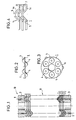
- the drive shaft for the wheels of a motor vehicle which can be seen in FIG. 1 and is generally indicated by the reference numeral 10, has two flanges 3 which are fastened by screws 9, 8 to the units (not shown) to be connected to one another.
- the flexible intermediate piece 11 between the two rigid flanges 3 is formed by an alternating sequence of disk-shaped, dimensionally stable segments 1 and disk-shaped, flexible segments 2.
- the disk-shaped, dimensionally stable segments 1 are provided with funnel-shaped projections 4 from their two surfaces, which in turn lead to funnel-shaped depressions on the other side.
- funnel-shaped projections 4 from their two surfaces, which in turn lead to funnel-shaped depressions on the other side.
- the number of funnel-shaped projections 4 can be varied, but should not be less than three in order not to interrupt the positive-locking twist connection between the adjacent rigid segments 1 when stressed.
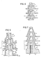
- FIGS. 4 to 7 show different shapes of the funnel-shaped projections 4: all embodiments are based on a disk-shaped base body 1 a of the dimensionally stable segments 1, on which the funnel-shaped projections 4 are formed.
- the funnel-shaped projections 4 have side walls 4a, which extend approximately at an angle of 45 ° to the disk-shaped base surface 1a.
- the funnel-shaped projections 4 consist of a cylindrical base body 4b, which is followed by a further cylindrical body 4c with a reduced diameter.
- the transition between the two cylindrical bodies 4b and 4c takes place on the right side as shown in FIG. 5 by a flat surface 4d and on the left side by a curved surface 4e.
- the two cylindrical bodies 4b and 4c are connected to one another by a conical transition region 4f.
- FIG. 7 shows an embodiment in which the side walls of the funnel-shaped projections 4 run approximately at an angle of 70 to 75 ° to the base surface 1a and are approximately twice as deep as the projections 4 in the embodiment according to FIG. 4.
- end faces of the flanges 3 facing the intermediate piece 11 are provided with corresponding funnel-shaped projections or depressions (see FIG. 1), so that there are also positive and non-positive twist connections on these end faces.
- the tips of the funnel-shaped projections 4 or the complementary funnel-shaped recesses are provided with through openings 6, as can be seen, for example, in FIG. 4.
- Between the disc-shaped, dimensionally stable segments 1 with the funnel-shaped projections or depressions are flexible, disc-shaped segments 2, which consist of an elastomeric material, in particular rubber.
- the flexible disk-shaped segments 2 can be produced by casting;
- the dimensionally stable segments 1 are held at a predetermined distance from one another by the spacers 7 shown in FIG. 4, so that spaces are created between the dimensionally stable segments 1.
- the rubber compound is poured into these spaces and vulcanized. After the vulcanization, the spacers 7 are removed so that there is no longer a rigid connection between the dimensionally stable segments 1.
- the viscous rubber mass also penetrates into the openings 6 of the funnel-shaped projections or recesses, so that even in this region - and not only in the region of the funnel-shaped projections and recesses - a positive-locking bending connection due to the push-button-like design of those reaching through the openings 6 Projections of the flexible segments arise.
- the funnel-shaped projections 4 of the shaped segments thus engage through the adjacent flexible segment 2 into the associated funnel-shaped recesses of the next dimensionally stable segment 1, whereby there is a positive twist connection between the adjacent dimensionally stable segments 1.
- the transmission of the torsional and bending moments acting on the drive shaft 10 thus takes place by a combination of positive and positive locking, possibly also supported by a material locking, if the surfaces of the flexible segments 2 are provided with an adhesive.
- the incompressibility of the elastomeric material, in particular in the pressure zone of the curved shaft section, is used, as a result of which the shaft is self-centered and the deflection in the bending direction is reduced.
- This reduction in the deflection in the bending direction in turn leads to a desired increase in the bending-critical speed of the drive shaft.
Landscapes
- Engineering & Computer Science (AREA)
- General Engineering & Computer Science (AREA)
- Mechanical Engineering (AREA)
- Health & Medical Sciences (AREA)
- Oral & Maxillofacial Surgery (AREA)
- Arrangement Or Mounting Of Propulsion Units For Vehicles (AREA)
- Motor Power Transmission Devices (AREA)
- Shafts, Cranks, Connecting Bars, And Related Bearings (AREA)
- Flexible Shafts (AREA)
Description
Die Erfindung bezieht sich auf eine verformbare Antriebswelle, insbesondere für die Räder von Kraftfahrzeugen mit antriebs- bzw. abtriebsseitigen Anschlüssen und einem flexiblen Zwischenstück, das aus einer Vielzahl von hintereinanderliegenden, scheibenförmigen und formsteifen Segmenten mit beidseitig abragenden und ineinandergreifenden Vorsprüngen sowie dazwischenliegenden flexiblen Segmenten aus elamstomerem Material besteht.The invention relates to a deformable drive shaft, in particular for the wheels of motor vehicles with drive or output-side connections and a flexible intermediate piece, which consists of a plurality of successive, disc-shaped and dimensionally stable segments with mutually protruding and interlocking projections as well as flexible segments made of elastomeric Material exists.
Eine derartige Welle ist aus der GB-A-616 987 bekannt. Dabei weisen die formsteifen scheibenförmigen Segmente auf beiden Seiten sich radial erstreckende Stege auf, zwischen denen in Umfangsrichtung kreisringabschnittförmige Gummielemente angeordnet sind.Such a shaft is known from GB-A-616 987. The dimensionally stable, disc-shaped segments have radially extending webs on both sides, between which are arranged rubber-segment-shaped rubber elements in the circumferential direction.
Eine solche Welle kann zwar relativ große Tordierungen um die Längsachse aufnehmen, für die Übertragung großer Drehmomente ist sie jedoch wegen der relativ großvolumigen, auf Druck beanspruchten Gummielemente nur weniger geeignet.Although such a shaft can accommodate relatively large twists around the longitudinal axis, it is only less suitable for the transmission of high torques because of the relatively large-volume rubber elements that are subjected to pressure.
Demgegenüber liegt der vorliegenden Erfindung die Aufgabe zugrunde, eine verformbare Antriebswelle zu schaffen, die torsionssteif ist, also relativ große Drehmomente übertragen kann und gleichzeitig biegeweich ist, also auch große Verschiebungen zwischen den zu verbindenden Aggregaten übertragen kann, und die darüber hinaus die Übertragung von Körperschall isoliert.In contrast, the present invention has for its object to provide a deformable drive shaft that is torsionally rigid, i.e. can transmit relatively large torques and at the same time is flexible, that is also able to transmit large displacements between the units to be connected, and which can also transmit structure-borne noise isolated.
Zur Lösung dieser Aufgabe ist erfindungsgemäß vorgesehen, daß die formsteifen Segmente auf mindestens einer Seite trichterförmige Vorsprünge und auf der jeweils gegenüberliegenden Seite entsprechende trichterförmige Hohlräume aufweisen, daß die trichterförmigen Vorsprünge des einen formsteifen Segmentes durch das benachbarte flexible Segment hindurch in die trichterförmigen Hohlräume des benachbarten formsteifen Segmentes eingreifen und daß die formsteifen und die flexiblen Segmente an den Verbindungsflächen gehaftet sind.To achieve this object, the invention provides that the dimensionally stable segments have funnel-shaped projections on at least one side and corresponding funnel-shaped cavities on the opposite side in each case, that the funnel-shaped projections of one dimensionally stable segment through the adjacent flexible segment into the funnel-shaped cavities of the adjacent dimensionally rigid Intervene segment and that the rigid and flexible segments are stuck to the connecting surfaces.
Durch die relativ geringe Dicke der flexiblen Segmente ergibt sich somit eine formschlüssige Verdreh-Verbindung zwischen benachbarten formsteifen Segmenten, wodurch eine hohe Torsionssteifigkeit geschaffen ist.The relatively small thickness of the flexible segments thus results in a positive twist connection between adjacent dimensionally stable segments, which creates a high degree of torsional rigidity.
Die flexiblen Segmente werden aus einem geeigneten elastomeren Material, bspw. durch ausvulkanisierte Gummischichten, hergestellt, die zwischen den benachbarten formsteifen Segmenten angeordnet sind.The flexible segments are made of a suitable elastomeric material, for example by vulcanized rubber layers, which are arranged between the adjacent dimensionally stable segments.
Diese flexiblen Segmente können auch durch einen Gießvorgang hergestellt werden ; zu diesem Zweck werden die formsteifen Segmente in definierten Abständen voneinander angeordnet ; der gewünschte Abstand wird durch Abstandhalter gewährleistet, die an den Außenrändern der formsteifen Segmente angebracht ist.These flexible segments can also be produced by a casting process; For this purpose, the dimensionally stable segments are arranged at defined distances from one another; the desired distance is ensured by spacers, which are attached to the outer edges of the dimensionally stable segments.
Das Kautschukmaterial wird in die Zwischenräume zwischen den einzelnen formsteifen Segmente eingefüllt und ausvulkanisiert ; anschlie-' ßend, nämlich z. B. nach dem Ausvulkanisieren des Kautschuks zum Gummi, werden die Abstandshalter entfernt, so daß keine starre Verbindung zwischen den benachbarten formsteifen Segmenten mehr besteht.The rubber material is filled into the spaces between the individual dimensionally stable segments and vulcanized; then, namely z. B. after vulcanizing the rubber to rubber, the spacers are removed so that there is no more rigid connection between the adjacent dimensionally stable segments.
Zwischen den benachbarten flexiblen und formsteifen Segmenten kann eine formschlüssige axiale Verbindung vorgesehen sein ; zu diesem Zweck sind die flexiblen Segmente mit druckknopfartigen Vorsprüngen versehen, die durch Öffnungen in den trichterförmigen Vorsprüngen der formsteifen Segmente greifen und dadurch eine zusätzliche Biege-Verbindung in der Zugzone herstellen.A positive axial connection can be provided between the adjacent flexible and dimensionally stable segments; for this purpose, the flexible segments are provided with push-button-like projections which engage through openings in the funnel-shaped projections of the dimensionally stable segments and thereby produce an additional bent connection in the tensile zone.
Die Übertragung von Torsion- und Biegemomenten, die auf diese Antriebswelle einwirken, erfolgt also teilweise durch Kraftschluß, teilweise durch Formschluß und teilweise durch Stoffschluß, so daß sich einerseits eine hohe Torsionssteifigkeit, wie sie für die Übertragung von hohen Drehmomenten erforderlich ist, und an dererseits eine hohe Verformbarkeit senkrecht zur Richtung der Antriebswelle ergibt, wie sie bei starken Relativbewegungen der miteinander zu verbindenden Aggregate benötigt wird.The transmission of torsion and bending moments, which act on this drive shaft, takes place partly through frictional connection, partly through positive locking and partly through material locking, so that on the one hand a high torsional stiffness, as required for the transmission of high torques, and on the other hand A high deformability perpendicular to the direction of the drive shaft results, as is required for strong relative movements of the units to be connected to one another.
Die Erfindung wird im folgenden anhand von Ausführungsbeispielen unter Bezugnahme auf die beiliegenden, schematischen Zeichnungen näher erläutert. Es zeigen
- Fig. 1 einen Schnitt durch eine Antriebswelle,
- Fig. 2 eine Seitenansicht eines formsteifen Segmentes,
- Fig. 3 eine Draufsicht auf ein formsteifes Segment,
- Fig. 4 die räumliche Anordnung von drei formsteifen Segmenten vor dem Eingießen des Kautschuks,
- Fig. 5 eine Modifikation der trichterförmigen Vorsprünge,
- Fig. 6 eine weitere Modifikation der trichterförmige Vorsprünge, und
- Fig. 7 eine weitere Modifikation der trichterförmigen Vorsprünge.
- 1 shows a section through a drive shaft,
- 2 is a side view of a dimensionally stable segment,
- 3 is a plan view of a rigid segment,
- 4 shows the spatial arrangement of three dimensionally stable segments before the rubber is poured in,
- 5 shows a modification of the funnel-shaped projections,
- Fig. 6 shows a further modification of the funnel-shaped projections, and
- Fig. 7 shows a further modification of the funnel-shaped projections.
Die aus Figur 1 ersichtliche, allgemein durch das Bezugszeichen 10 angedeutete Antriebswelle für die Räder eines Kraftfahrzeugs weist zwei Flansche 3 auf, die durch Schrauben 9, 8 an den miteinander zu verbindenden Aggregaten (nicht dargestellt) befestigt sind.The drive shaft for the wheels of a motor vehicle, which can be seen in FIG. 1 and is generally indicated by the
Das flexible Zwischenstück 11 zwischen den beiden starren Flanschen 3 wird durch eine abwechselnde Folge von scheibenförmigen, formsteifen Segmenten 1 und scheibenförmigen, flexiblen Segmenten 2 gebildet.The flexible
Wie man aus den Figuren 2 und 3 erkennt, sind die scheibenförmigen, formsteifen Segmente 1 aus ihren beiden Oberflächen mit trichterförmigen Vorsprüngen 4 versehen, die wiederum auf der anderen Seite zu trichterförmigen Vertiefungen führen. Bei der Ausführungsform nach Fig. 3 sind bspw. auf jeder Seite drei trichterförmige Vorsprünge und dementsprechend auch drei trichterförmige Vertiefungen vorgesehen, wobei auf jeder Seite Vorsprünge und Vertiefungen einander abwechseln.As can be seen from FIGS. 2 and 3, the disk-shaped, dimensionally
Die Zahl der trichterförmigen Vorsprünge 4 kann variiert werden, sollte jedoch drei nicht unterschreiten, um die formschlussige Verdreh-Verbindung zwischen den benachbarten formsteifen Segmenten 1 bei Beanspruchung nicht zu unterbrechen.The number of funnel-
Die Figuren 4 bis 7 zeigen verschiedene Formen der trichterförmigen Vorsprünge 4 : Alle Ausführungsformen gehen von einem scheibenförmigen Grundkörper 1a der formsteifen Segmente 1 aus, auf der die trichterförmigen Vorsprünge 4 ausgebildet sind.FIGS. 4 to 7 show different shapes of the funnel-shaped projections 4: all embodiments are based on a disk-
Bei der Ausführungsform nach Fig. 4 weisen die trichterförmigen Vorsprünge 4 Seitenwände 4a auf, die etwa unter einem Winkel von 45° zur scheibenförmigen Grundfläche 1a verlaufen.In the embodiment according to FIG. 4, the funnel-
Bei der Ausführungsform nach Fig. 5 bestehen die trichterförmigen Vorsprünge 4 aus einem zylindrischen Grundkörper 4b, an den sich ein weiterer zylindrischer Körper 4c mit verringerten Durchmesser anschließt. Der Übergang zwischen den beiden zylindrischen Körpern 4b und 4c erfolgt auf der gemäß der Darstellung in Fig. 5 rechten Seite durch eine ebene Fläche 4d und auf der linken Seite durch eine gewölbte Fläche 4e.In the embodiment according to FIG. 5, the funnel-
Bei der Ausführungsform nach Fig. 6 sind die beiden zylindrischen Körper 4b und 4c durch einen konischen Übergangsbereich 4f miteinander verbunden.In the embodiment according to FIG. 6, the two cylindrical bodies 4b and 4c are connected to one another by a conical transition region 4f.
Fig. 7 zeigt schließlich eine Ausführungsform, bei der die Seitenwände der trichterförmigen Vorsprünge 4 etwa unter einem Winkel von 70 bis 75° zur Grundfläche 1a verlaufen und etwa doppelt so tief wie die Vorsprünge 4 bei der Ausführungsform nach Fig. 4 sind.Finally, FIG. 7 shows an embodiment in which the side walls of the funnel-
Die dem Zwischenstück 11 zugewandten Stirnflächen der Flansche 3 sind mit entsprechenden, trichterförmigen Vorsprüngen bzw. Vertiefungen (siehe Fig. 1) versehen, so daß sich auch an diesen Stirnflächen form- und kraftschlüssige Verdreh-Verbindungen ergeben.The end faces of the flanges 3 facing the
Die Spitzen der trichterförmigen Vorsprünge 4 bzw. der dazu komplementären trichterförmigen Aussparungen sind mit durchgehenden Öffnungen 6 versehen, wie man bspw. in Fig. 4 erkennt. Zwischen den scheibenförmigen, formsteifen Segmenten 1 mit den trichterförmigen Vorsprüngen bzw. Vertiefungen sind flexible, scheibenförmige Segmente 2 angebracht, die aus einem elastomeren Material, insbesondere Gummi bestehen.The tips of the funnel-
Die flexiblen scheibenförmigen Segmente 2 können durch Gießen hergestellt werden ; zu diesem Zweck werden die formsteifen Segmente 1 durch die aus Fig. 4 ersichtlichen Abstandshalter 7 in einem vorgegebenen Abstand voneinander gehalten, so daß Zwischenräume zwischen den formsteifen Segmenten 1 entstehen. In diese Zwischenräume wird die Kautschukmasse eingegossen und ausvulkanisiert. Nach Beendigung der Vulkanisation werden die Abstandshalter 7 entfernt, so daß keine starre Verbindung zwischen den formsteifen Segmenten 1 mehr besteht.The flexible disk-shaped segments 2 can be produced by casting; For this purpose, the dimensionally
Die zähflüssige Kautschukmasse dringt auch in die Öffnungen 6 der trichterförmigen Vorsprünge bzw. Aussparungen ein, so daß auch in diesem Bereich - und nicht nur im Bereich der trichterförmigen Vorsprünge und Aussparungen - eine formschlüssige Biege-Verbindung durch die druckknopfartige Ausbildung der durch die Öffnungen 6 greifenden Vorsprünge der flexiblen Segmenten entsteht.The viscous rubber mass also penetrates into the openings 6 of the funnel-shaped projections or recesses, so that even in this region - and not only in the region of the funnel-shaped projections and recesses - a positive-locking bending connection due to the push-button-like design of those reaching through the openings 6 Projections of the flexible segments arise.
Die trichterförmigen Vorsprünge 4 der formstreifen Segmente greifen also durch das benachbarte flexible Segment 2 hindurch in die zugehörigen trichterförmigen Aussparungen des nächsten formsteifen Segmentes 1 ein, wodurch eine formschlüssige Verdreh-Verbindung zwischen den benachbarten formsteifen Segmenten 1 besteht.The funnel-
Durch die zwischen den formsteifen Segmenten 1 befindliche Gummischicht ist jedoch eine gewisse Torsionsbewegung den benachbarten formsteifen Segmenten 1 möglich ; außerdem erlaubt dies eine gewisse Verformung der Welle 10 senkrecht zu ihrer Erstreckungsrichtung.Due to the rubber layer located between the dimensionally
Außerdem liegt an den in Figur 4 durch das Bezugszeichen 5 angedeuteten Verbindungsflächen zwischen formsteifen, harten Segmenten 1 und flexiblen Segmenten 2 eine weitere kraftschlüssige Verdreh- und Biege-Verbindung vor, nämlich an den Übergängen zwischen der Grundfläche 1a und den trichterförmigen Vorsprüngen 4, die noch durch die formschlüssige Zugverbindung in den Öffnungen 6 der trichterförmigen Vorsprünge 4 unterstützt wird.In addition, there is a further non-positive twist and bend connection at the connecting surfaces indicated by reference numeral 5 in FIG. 4 between rigid
Die Übertragung der auf die Antriebswelle 10 einwirkenden Torsions- und Biegemomente erfolgt also durch eine Kombination von Kraft- und Formschluß, gegebenenfalls noch unterstützt durch einen Stoffschluß, wenn man nämlich die Oberflächen der flexiblen Segmente 2 mit einem Haftmittel versieht.The transmission of the torsional and bending moments acting on the
Bei einer solchen verformbaren Antriebswelle wird die Inkompressibilität des elastomeren Materials, insbesondere in der Druckzone des gebogenen Wellenabschnittes, ausgenutzt, wodurch eine Selbstzentrierung der Welle und eine Verringung der Auslenkung in Biegerichtung erreicht werden. Diese Verringerung der Auslenkung in Biegerichtung führt wiederum zu einer erwünschten Erhöhung der biegekritischen Drehzahl der Antriebswelle.In the case of such a deformable drive shaft, the incompressibility of the elastomeric material, in particular in the pressure zone of the curved shaft section, is used, as a result of which the shaft is self-centered and the deflection in the bending direction is reduced. This reduction in the deflection in the bending direction in turn leads to a desired increase in the bending-critical speed of the drive shaft.
Claims (8)
Applications Claiming Priority (2)
| Application Number | Priority Date | Filing Date | Title |
|---|---|---|---|
| DE19853520251 DE3520251A1 (en) | 1985-06-05 | 1985-06-05 | DEFORMABLE DRIVE SHAFT |
| DE3520251 | 1985-06-05 |
Publications (2)
| Publication Number | Publication Date |
|---|---|
| EP0204323A1 EP0204323A1 (en) | 1986-12-10 |
| EP0204323B1 true EP0204323B1 (en) | 1989-03-15 |
Family
ID=6272563
Family Applications (1)
| Application Number | Title | Priority Date | Filing Date |
|---|---|---|---|
| EP86107578A Expired EP0204323B1 (en) | 1985-06-05 | 1986-06-04 | Deformable drive shaft |
Country Status (5)
| Country | Link |
|---|---|
| US (1) | US4743219A (en) |
| EP (1) | EP0204323B1 (en) |
| JP (1) | JPS61282617A (en) |
| DE (2) | DE3520251A1 (en) |
| ES (1) | ES294539Y (en) |
Families Citing this family (3)
| Publication number | Priority date | Publication date | Assignee | Title |
|---|---|---|---|---|
| DE102005032865B4 (en) * | 2005-07-14 | 2009-08-06 | Ifa-Maschinenbau Gmbh | propeller shaft |
| ITBG20080062A1 (en) * | 2008-12-18 | 2009-03-19 | Gianfranco Taiocchi | DYNAMIC TAIL JOINT. |
| DE102013018873B3 (en) * | 2013-11-12 | 2014-11-27 | Schenck Process Gmbh | screening device |
Family Cites Families (18)
| Publication number | Priority date | Publication date | Assignee | Title |
|---|---|---|---|---|
| GB256134A (en) * | 1926-02-16 | 1926-08-05 | Thomas Henry Large | Improvements in and relating to flexible shaft couplings and like joints |
| GB322154A (en) * | 1929-07-24 | 1929-11-28 | Thomas Henry Large | Improvements in or relating to flexible shaft couplings and the like |
| US2207496A (en) * | 1932-10-20 | 1940-07-09 | Edith W Carlson | Power transmission |
| US2105702A (en) * | 1934-08-06 | 1938-01-18 | Herman J Scholtze | Flexible shaft coupling |
| DE668217C (en) * | 1936-11-22 | 1938-11-28 | Olga Stamm Geb Paasche | Flexible shaft |
| GB616987A (en) * | 1945-07-12 | 1949-01-31 | Gennaro Pittaluga | An improved flexible coupling |
| US2603073A (en) * | 1945-11-19 | 1952-07-15 | Nield Herbert | Flexible rotary shaft |
| US2822896A (en) * | 1952-02-23 | 1958-02-11 | Valentin Krause | Collapsible device |
| FR1135337A (en) * | 1954-07-06 | 1957-04-26 | Gomma Antivibranti Applic | Improvements to rubber torsion springs and their application as anti-shake elastic seals |
| US2928264A (en) * | 1957-03-14 | 1960-03-15 | Hudson Engineering Corp | Drive couplings |
| US3296826A (en) * | 1960-06-29 | 1967-01-10 | High Voltage Engineering Corp | Insulating shaft |
| US3606392A (en) * | 1969-04-14 | 1971-09-20 | Smith Ind International Inc | Vibration dampener |
| GB1352231A (en) * | 1971-09-03 | 1974-05-08 | Jorn R | Flexible coupling |
| US4040690A (en) * | 1975-11-17 | 1977-08-09 | Lord Corporation | Laminated bearing |
| JPS5482547A (en) * | 1977-11-25 | 1979-06-30 | Shakespeare Co | Drive shaft assembly and method of producing same |
| DE3139247A1 (en) * | 1980-10-06 | 1982-07-22 | Celanese Corp., 10036 New York, N.Y. | Composite vehicle drive shaft dispensing with universal-joint shaft couplings |
| DE3045141C2 (en) * | 1980-11-29 | 1987-07-09 | Messerschmitt-Bölkow-Blohm GmbH, 8000 München | Safety steering column for motor vehicles |
| DE3310695A1 (en) * | 1983-03-24 | 1984-09-27 | Hackforth GmbH & Co KG, 4690 Herne | HIGHLY ELASTIC SHAFT COUPLING |
-
1985
- 1985-06-05 DE DE19853520251 patent/DE3520251A1/en active Granted
-
1986
- 1986-06-03 ES ES1986294539U patent/ES294539Y/en not_active Expired
- 1986-06-03 JP JP61129027A patent/JPS61282617A/en active Pending
- 1986-06-04 EP EP86107578A patent/EP0204323B1/en not_active Expired
- 1986-06-04 DE DE8686107578T patent/DE3662440D1/en not_active Expired
- 1986-06-05 US US06/871,071 patent/US4743219A/en not_active Expired - Fee Related
Also Published As
| Publication number | Publication date |
|---|---|
| ES294539U (en) | 1986-11-01 |
| EP0204323A1 (en) | 1986-12-10 |
| DE3662440D1 (en) | 1989-04-20 |
| DE3520251A1 (en) | 1986-12-11 |
| ES294539Y (en) | 1987-07-16 |
| JPS61282617A (en) | 1986-12-12 |
| US4743219A (en) | 1988-05-10 |
| DE3520251C2 (en) | 1988-01-14 |
Similar Documents
| Publication | Publication Date | Title |
|---|---|---|
| DE68904401T2 (en) | BEARING FOR A ROTATING SHAFT. | |
| DE102011008396A1 (en) | Coupling for damping connection of two shaft sections in particular a steering shaft, and steering shaft and method for producing a corresponding coupling | |
| DE2733880A1 (en) | Vehicle friction clutch disc with separate hub plate - has flexible connection in space between riveted hub and friction ring | |
| EP0651371A2 (en) | Vibration absorber for damping of structural sound | |
| DE3843496C1 (en) | ||
| EP0204323B1 (en) | Deformable drive shaft | |
| DE3419176C2 (en) | ||
| DE102016123422B4 (en) | Hollow shaft made of a fiber composite material and winding shaft for the production of such a hollow shaft | |
| DE3108007A1 (en) | "ELASTIC CLUTCH ELEMENTS" | |
| DE2920074C2 (en) | Plate coupling | |
| DE1600088B1 (en) | ELASTIC COUPLING | |
| DE3021676A1 (en) | ELASTIC SUPPORT ELEMENT, IN PARTICULAR FOR THE DRIVE ENGINE IN A MOTOR VEHICLE | |
| DE3026756A1 (en) | DOUBLE AXLE DRIVE FOR BOGIE BOGIES | |
| DE1286420B (en) | Elastic coupling for the steering column of motor vehicles | |
| DE2612829C2 (en) | Split steering column | |
| DE2336121A1 (en) | ELASTIC COUPLING FOR POWER TRANSMISSION WITH HIGH INITIAL FLEXIBILITY, IN PARTICULAR FOR CLUTCH DISCS | |
| DE2124435A1 (en) | Elastic coupling and process for their manufacture | |
| DE3432602C2 (en) | ||
| EP0204322B1 (en) | Drive shaft | |
| DE2036041A1 (en) | Joint disc | |
| DE102009009683A1 (en) | Torque transmission device for e.g. automobile, has coupling elements for coupling pivot points of drive element with pivot points of output element in opposite peripheral directions, where elements are formed as leaf spring-like elements | |
| EP0699847A2 (en) | Rotational vibration damper, particularly for the driveline of a motor vehicle | |
| DE3131694A1 (en) | "JOINT CLUTCH" | |
| EP1308642B1 (en) | Hollow shaft | |
| DE102011117298A1 (en) | Shaft coupling for use in vehicle, has two transfer element-disks connected together at and/or adjacent to corner points, and two transfer elements adjacently connected together at corner points by clamps in form-fit manner |
Legal Events
| Date | Code | Title | Description |
|---|---|---|---|
| PUAI | Public reference made under article 153(3) epc to a published international application that has entered the european phase |
Free format text: ORIGINAL CODE: 0009012 |
|
| 17P | Request for examination filed |
Effective date: 19860604 |
|
| AK | Designated contracting states |
Kind code of ref document: A1 Designated state(s): DE FR GB IT SE |
|
| 17Q | First examination report despatched |
Effective date: 19880226 |
|
| RAP1 | Party data changed (applicant data changed or rights of an application transferred) |
Owner name: METZELER GESELLSCHAFT MIT BESCHRAENKTER HAFTUNG |
|
| RAP3 | Party data changed (applicant data changed or rights of an application transferred) |
Owner name: METZELER GESELLSCHAFT MIT BESCHRAENKTER HAFTUNG |
|
| GRAA | (expected) grant |
Free format text: ORIGINAL CODE: 0009210 |
|
| AK | Designated contracting states |
Kind code of ref document: B1 Designated state(s): DE FR GB IT SE |
|
| PG25 | Lapsed in a contracting state [announced via postgrant information from national office to epo] |
Ref country code: IT Free format text: LAPSE BECAUSE OF FAILURE TO SUBMIT A TRANSLATION OF THE DESCRIPTION OR TO PAY THE FEE WITHIN THE PRE;WARNING: LAPSES OF ITALIAN PATENTS WITH EFFECTIVE DATE BEFORE 2007 MAY HAVE OCCURRED AT ANY TIME BEFORE 2007. THE CORRECT EFFECTIVE DATE MAY BE DIFFERENT FROM THE ONE RECORDED.SCRIBED TIME-LIMIT Effective date: 19890315 Ref country code: FR Free format text: THE PATENT HAS BEEN ANNULLED BY A DECISION OF A NATIONAL AUTHORITY Effective date: 19890315 Ref country code: GB Free format text: LAPSE BECAUSE OF NON-PAYMENT OF DUE FEES Effective date: 19890315 |
|
| REF | Corresponds to: |
Ref document number: 3662440 Country of ref document: DE Date of ref document: 19890420 |
|
| PG25 | Lapsed in a contracting state [announced via postgrant information from national office to epo] |
Ref country code: SE Effective date: 19890605 |
|
| PGFP | Annual fee paid to national office [announced via postgrant information from national office to epo] |
Ref country code: DE Payment date: 19890711 Year of fee payment: 4 |
|
| EN | Fr: translation not filed | ||
| GBV | Gb: ep patent (uk) treated as always having been void in accordance with gb section 77(7)/1977 [no translation filed] | ||
| PLBE | No opposition filed within time limit |
Free format text: ORIGINAL CODE: 0009261 |
|
| STAA | Information on the status of an ep patent application or granted ep patent |
Free format text: STATUS: NO OPPOSITION FILED WITHIN TIME LIMIT |
|
| 26N | No opposition filed | ||
| PG25 | Lapsed in a contracting state [announced via postgrant information from national office to epo] |
Ref country code: DE Effective date: 19910301 |
|
| EUG | Se: european patent has lapsed |
Ref document number: 86107578.6 Effective date: 19900418 |