EP0204297B1 - Charged particle emission source structure - Google Patents
Charged particle emission source structure Download PDFInfo
- Publication number
- EP0204297B1 EP0204297B1 EP86107442A EP86107442A EP0204297B1 EP 0204297 B1 EP0204297 B1 EP 0204297B1 EP 86107442 A EP86107442 A EP 86107442A EP 86107442 A EP86107442 A EP 86107442A EP 0204297 B1 EP0204297 B1 EP 0204297B1
- Authority
- EP
- European Patent Office
- Prior art keywords
- electrode
- needle
- heat
- source structure
- charged particle
- Prior art date
- Legal status (The legal status is an assumption and is not a legal conclusion. Google has not performed a legal analysis and makes no representation as to the accuracy of the status listed.)
- Expired
Links
- 239000002245 particle Substances 0.000 title claims description 41
- 229910001338 liquidmetal Inorganic materials 0.000 claims description 68
- 238000005192 partition Methods 0.000 claims description 34
- 238000000605 extraction Methods 0.000 claims description 31
- 150000002500 ions Chemical class 0.000 claims description 29
- 229910052751 metal Inorganic materials 0.000 claims description 28
- 239000002184 metal Substances 0.000 claims description 28
- 238000010438 heat treatment Methods 0.000 claims description 23
- 229910045601 alloy Inorganic materials 0.000 claims description 22
- 239000000956 alloy Substances 0.000 claims description 22
- 239000000463 material Substances 0.000 claims description 20
- OKTJSMMVPCPJKN-UHFFFAOYSA-N Carbon Chemical compound [C] OKTJSMMVPCPJKN-UHFFFAOYSA-N 0.000 claims description 17
- 229910052796 boron Inorganic materials 0.000 claims description 15
- 229910052721 tungsten Inorganic materials 0.000 claims description 14
- 238000005245 sintering Methods 0.000 claims description 12
- 229910052715 tantalum Inorganic materials 0.000 claims description 12
- WFKWXMTUELFFGS-UHFFFAOYSA-N tungsten Chemical compound [W] WFKWXMTUELFFGS-UHFFFAOYSA-N 0.000 claims description 12
- 239000013078 crystal Substances 0.000 claims description 11
- 238000002844 melting Methods 0.000 claims description 11
- 230000008018 melting Effects 0.000 claims description 11
- 239000000843 powder Substances 0.000 claims description 11
- 229910052799 carbon Inorganic materials 0.000 claims description 10
- 239000011651 chromium Substances 0.000 claims description 9
- 229910052750 molybdenum Inorganic materials 0.000 claims description 9
- 239000010937 tungsten Substances 0.000 claims description 9
- 229910052804 chromium Inorganic materials 0.000 claims description 8
- 238000012545 processing Methods 0.000 claims description 8
- 238000009736 wetting Methods 0.000 claims description 8
- 230000005684 electric field Effects 0.000 claims description 6
- 229910052759 nickel Inorganic materials 0.000 claims description 6
- ZOXJGFHDIHLPTG-UHFFFAOYSA-N Boron Chemical compound [B] ZOXJGFHDIHLPTG-UHFFFAOYSA-N 0.000 claims description 5
- 229910021397 glassy carbon Inorganic materials 0.000 claims description 5
- 238000007731 hot pressing Methods 0.000 claims description 5
- 239000000203 mixture Substances 0.000 claims description 5
- 229910052763 palladium Inorganic materials 0.000 claims description 5
- VYZAMTAEIAYCRO-UHFFFAOYSA-N Chromium Chemical compound [Cr] VYZAMTAEIAYCRO-UHFFFAOYSA-N 0.000 claims description 4
- ZOKXTWBITQBERF-UHFFFAOYSA-N Molybdenum Chemical compound [Mo] ZOKXTWBITQBERF-UHFFFAOYSA-N 0.000 claims description 4
- 239000011733 molybdenum Substances 0.000 claims description 4
- 229910052710 silicon Inorganic materials 0.000 claims description 4
- 229910052580 B4C Inorganic materials 0.000 claims description 3
- XUIMIQQOPSSXEZ-UHFFFAOYSA-N Silicon Chemical compound [Si] XUIMIQQOPSSXEZ-UHFFFAOYSA-N 0.000 claims description 3
- INAHAJYZKVIDIZ-UHFFFAOYSA-N boron carbide Chemical compound B12B3B4C32B41 INAHAJYZKVIDIZ-UHFFFAOYSA-N 0.000 claims description 3
- 239000003575 carbonaceous material Substances 0.000 claims description 3
- 150000002484 inorganic compounds Chemical class 0.000 claims description 3
- 229910010272 inorganic material Inorganic materials 0.000 claims description 3
- 229910052742 iron Inorganic materials 0.000 claims description 3
- 150000004767 nitrides Chemical class 0.000 claims description 3
- 239000010703 silicon Substances 0.000 claims description 3
- 229910052719 titanium Inorganic materials 0.000 claims description 3
- XLYOFNOQVPJJNP-UHFFFAOYSA-N water Substances O XLYOFNOQVPJJNP-UHFFFAOYSA-N 0.000 claims description 3
- 229910052726 zirconium Inorganic materials 0.000 claims description 3
- 208000032544 Cicatrix Diseases 0.000 claims description 2
- 231100000241 scar Toxicity 0.000 claims description 2
- 230000037387 scars Effects 0.000 claims description 2
- OFEAOSSMQHGXMM-UHFFFAOYSA-N 12007-10-2 Chemical compound [W].[W]=[B] OFEAOSSMQHGXMM-UHFFFAOYSA-N 0.000 claims 1
- 238000004898 kneading Methods 0.000 claims 1
- 238000010884 ion-beam technique Methods 0.000 description 25
- 238000010894 electron beam technology Methods 0.000 description 14
- 239000000126 substance Substances 0.000 description 11
- 238000000034 method Methods 0.000 description 9
- GUVRBAGPIYLISA-UHFFFAOYSA-N tantalum atom Chemical compound [Ta] GUVRBAGPIYLISA-UHFFFAOYSA-N 0.000 description 9
- 229910002804 graphite Inorganic materials 0.000 description 8
- 239000010439 graphite Substances 0.000 description 8
- 238000000151 deposition Methods 0.000 description 5
- 230000008021 deposition Effects 0.000 description 5
- 229910052790 beryllium Inorganic materials 0.000 description 4
- 239000011230 binding agent Substances 0.000 description 4
- 230000000052 comparative effect Effects 0.000 description 4
- 150000001875 compounds Chemical class 0.000 description 4
- 238000007667 floating Methods 0.000 description 4
- 239000007788 liquid Substances 0.000 description 4
- 229910019918 CrB2 Inorganic materials 0.000 description 3
- 230000003213 activating effect Effects 0.000 description 3
- 229910052785 arsenic Inorganic materials 0.000 description 3
- 238000001704 evaporation Methods 0.000 description 3
- 230000008020 evaporation Effects 0.000 description 3
- 238000003754 machining Methods 0.000 description 3
- 239000010936 titanium Substances 0.000 description 3
- UONOETXJSWQNOL-UHFFFAOYSA-N tungsten carbide Chemical compound [W+]#[C-] UONOETXJSWQNOL-UHFFFAOYSA-N 0.000 description 3
- XKRFYHLGVUSROY-UHFFFAOYSA-N Argon Chemical compound [Ar] XKRFYHLGVUSROY-UHFFFAOYSA-N 0.000 description 2
- QYEXBYZXHDUPRC-UHFFFAOYSA-N B#[Ti]#B Chemical compound B#[Ti]#B QYEXBYZXHDUPRC-UHFFFAOYSA-N 0.000 description 2
- 229910052684 Cerium Inorganic materials 0.000 description 2
- 229910008423 Si—B Inorganic materials 0.000 description 2
- 229910033181 TiB2 Inorganic materials 0.000 description 2
- 229910052782 aluminium Inorganic materials 0.000 description 2
- XAGFODPZIPBFFR-UHFFFAOYSA-N aluminium Chemical compound [Al] XAGFODPZIPBFFR-UHFFFAOYSA-N 0.000 description 2
- 238000006243 chemical reaction Methods 0.000 description 2
- 229910052733 gallium Inorganic materials 0.000 description 2
- 229910052738 indium Inorganic materials 0.000 description 2
- 238000002156 mixing Methods 0.000 description 2
- 239000010955 niobium Substances 0.000 description 2
- 229910052698 phosphorus Inorganic materials 0.000 description 2
- 229910052697 platinum Inorganic materials 0.000 description 2
- 238000005498 polishing Methods 0.000 description 2
- 230000009257 reactivity Effects 0.000 description 2
- 238000011160 research Methods 0.000 description 2
- 239000006104 solid solution Substances 0.000 description 2
- 238000003892 spreading Methods 0.000 description 2
- 230000007480 spreading Effects 0.000 description 2
- 229910052712 strontium Inorganic materials 0.000 description 2
- 238000012546 transfer Methods 0.000 description 2
- 238000003466 welding Methods 0.000 description 2
- 229910015365 Au—Si Inorganic materials 0.000 description 1
- 229910052582 BN Inorganic materials 0.000 description 1
- PZNSFCLAULLKQX-UHFFFAOYSA-N Boron nitride Chemical compound N#B PZNSFCLAULLKQX-UHFFFAOYSA-N 0.000 description 1
- GYHNNYVSQQEPJS-UHFFFAOYSA-N Gallium Chemical compound [Ga] GYHNNYVSQQEPJS-UHFFFAOYSA-N 0.000 description 1
- 229910015173 MoB2 Inorganic materials 0.000 description 1
- -1 Ni-B Chemical compound 0.000 description 1
- ATJFFYVFTNAWJD-UHFFFAOYSA-N Tin Chemical compound [Sn] ATJFFYVFTNAWJD-UHFFFAOYSA-N 0.000 description 1
- RTAQQCXQSZGOHL-UHFFFAOYSA-N Titanium Chemical compound [Ti] RTAQQCXQSZGOHL-UHFFFAOYSA-N 0.000 description 1
- QCWXUUIWCKQGHC-UHFFFAOYSA-N Zirconium Chemical compound [Zr] QCWXUUIWCKQGHC-UHFFFAOYSA-N 0.000 description 1
- 230000001133 acceleration Effects 0.000 description 1
- 230000004913 activation Effects 0.000 description 1
- 239000000853 adhesive Substances 0.000 description 1
- 230000001070 adhesive effect Effects 0.000 description 1
- 230000002411 adverse Effects 0.000 description 1
- 229910052786 argon Inorganic materials 0.000 description 1
- QVGXLLKOCUKJST-UHFFFAOYSA-N atomic oxygen Chemical compound [O] QVGXLLKOCUKJST-UHFFFAOYSA-N 0.000 description 1
- 229910052792 caesium Inorganic materials 0.000 description 1
- GWXLDORMOJMVQZ-UHFFFAOYSA-N cerium Chemical compound [Ce] GWXLDORMOJMVQZ-UHFFFAOYSA-N 0.000 description 1
- 230000008859 change Effects 0.000 description 1
- 238000005229 chemical vapour deposition Methods 0.000 description 1
- 239000002131 composite material Substances 0.000 description 1
- 238000005336 cracking Methods 0.000 description 1
- 238000005520 cutting process Methods 0.000 description 1
- 230000007547 defect Effects 0.000 description 1
- 238000009792 diffusion process Methods 0.000 description 1
- 238000001035 drying Methods 0.000 description 1
- 238000010285 flame spraying Methods 0.000 description 1
- 238000011010 flushing procedure Methods 0.000 description 1
- 239000007789 gas Substances 0.000 description 1
- 230000020169 heat generation Effects 0.000 description 1
- 230000006872 improvement Effects 0.000 description 1
- 230000006698 induction Effects 0.000 description 1
- 238000009413 insulation Methods 0.000 description 1
- 239000012212 insulator Substances 0.000 description 1
- 238000005468 ion implantation Methods 0.000 description 1
- 230000001788 irregular Effects 0.000 description 1
- 229910021645 metal ion Inorganic materials 0.000 description 1
- 238000003801 milling Methods 0.000 description 1
- 238000000465 moulding Methods 0.000 description 1
- 229910052758 niobium Inorganic materials 0.000 description 1
- GUCVJGMIXFAOAE-UHFFFAOYSA-N niobium atom Chemical compound [Nb] GUCVJGMIXFAOAE-UHFFFAOYSA-N 0.000 description 1
- 239000001301 oxygen Substances 0.000 description 1
- 229910052760 oxygen Inorganic materials 0.000 description 1
- 238000002360 preparation method Methods 0.000 description 1
- 230000008439 repair process Effects 0.000 description 1
- 239000011347 resin Substances 0.000 description 1
- 229920005989 resin Polymers 0.000 description 1
- 150000003839 salts Chemical class 0.000 description 1
- VSZWPYCFIRKVQL-UHFFFAOYSA-N selanylidenegallium;selenium Chemical compound [Se].[Se]=[Ga].[Se]=[Ga] VSZWPYCFIRKVQL-UHFFFAOYSA-N 0.000 description 1
- 239000004065 semiconductor Substances 0.000 description 1
- 230000035939 shock Effects 0.000 description 1
- CIOAGBVUUVVLOB-UHFFFAOYSA-N strontium atom Chemical compound [Sr] CIOAGBVUUVVLOB-UHFFFAOYSA-N 0.000 description 1
- 239000000758 substrate Substances 0.000 description 1
- 238000012360 testing method Methods 0.000 description 1
- 238000005979 thermal decomposition reaction Methods 0.000 description 1
- 229910003470 tongbaite Inorganic materials 0.000 description 1
Images


Classifications
-
- H—ELECTRICITY
- H01—ELECTRIC ELEMENTS
- H01J—ELECTRIC DISCHARGE TUBES OR DISCHARGE LAMPS
- H01J37/00—Discharge tubes with provision for introducing objects or material to be exposed to the discharge, e.g. for the purpose of examination or processing thereof
- H01J37/02—Details
- H01J37/04—Arrangements of electrodes and associated parts for generating or controlling the discharge, e.g. electron-optical arrangement or ion-optical arrangement
- H01J37/06—Electron sources; Electron guns
- H01J37/073—Electron guns using field emission, photo emission, or secondary emission electron sources
-
- H—ELECTRICITY
- H01—ELECTRIC ELEMENTS
- H01J—ELECTRIC DISCHARGE TUBES OR DISCHARGE LAMPS
- H01J27/00—Ion beam tubes
- H01J27/02—Ion sources; Ion guns
- H01J27/022—Details
-
- H—ELECTRICITY
- H01—ELECTRIC ELEMENTS
- H01J—ELECTRIC DISCHARGE TUBES OR DISCHARGE LAMPS
- H01J27/00—Ion beam tubes
- H01J27/02—Ion sources; Ion guns
- H01J27/26—Ion sources; Ion guns using surface ionisation, e.g. field effect ion sources, thermionic ion sources
-
- H—ELECTRICITY
- H01—ELECTRIC ELEMENTS
- H01J—ELECTRIC DISCHARGE TUBES OR DISCHARGE LAMPS
- H01J37/00—Discharge tubes with provision for introducing objects or material to be exposed to the discharge, e.g. for the purpose of examination or processing thereof
- H01J37/02—Details
- H01J37/04—Arrangements of electrodes and associated parts for generating or controlling the discharge, e.g. electron-optical arrangement or ion-optical arrangement
- H01J37/08—Ion sources; Ion guns
-
- H—ELECTRICITY
- H01—ELECTRIC ELEMENTS
- H01J—ELECTRIC DISCHARGE TUBES OR DISCHARGE LAMPS
- H01J2237/00—Discharge tubes exposing object to beam, e.g. for analysis treatment, etching, imaging
- H01J2237/06—Sources
- H01J2237/063—Electron sources
- H01J2237/06308—Thermionic sources
- H01J2237/06316—Schottky emission
Definitions
- the present invention relates to a charged particle emission source structure in accordance with the prior art portions of the independent claims 1, 2 and 3.
- Such an emission source is known from JP-A-5 835 829.
- An ion beam by means of a liquid metal is expected to be very useful, since it makes fine work to a level of nanometers possible, while the fine work by conventional electron beam exposure has a limit at a level of submicrons. Further, the ion beam is applicable to mask-less ion implantation, milling or X-ray mask repairs.
- a field emission electron beam or a thermal field emission electron beam is expected to be useful as an electron source for a low acceleration SEM used for e.g. observation of minute portions of semiconductor devices.
- this liquid metal ion source structure comprises a reservoir for a metal to be ionized, a needle-like electrode having a needle-like tip to which a liquid metal is supplied from the reservoir, a means for applying a strong electric field to the needle-like tip, and a heat-generating support member thermally connected to the reservoir or to the needle-like electrode and being capable of generating a heat when electrically energized, the supporting member being formed by a material having a poor affinity with the liquid metal JP-A-35829/1983).
- JP-A-5835829 discloses a charged particle emission source structure of the above-mentioned kind.
- This prior art structure comprises a needle-like electrode for emission of charged particles, a reservoir for a liquid metal for wetting the surface of the needle-like electrode and a heat-generating support member for heating the liquid metal and holding the reservoir.
- the heat-generating support is made of graphite having a poor affinity with a liquid metal to prevent needless diffusion of the liquid metal on the support.
- the needle-like electrode is made of a material having a high melting point and being usually brittle, and it was difficult to bond the reservoir orthe heater by a conventional simple method such as spot welding.
- a conventional simple method such as spot welding.
- the tip of single crystal tungsten is shaped into a needle-like shape by electropolishing, and an electric field is applied to the tip to obtain electron emission.
- the field emission electron source is required to be under a highly vacuumed condition at a level of not higher than 1,33-10- 8 Pa (10- 10 torr), and a high level of technique is required to maintain the highly vacuumed condition.
- conventional electron source structures have a drawback that it is impossible to maintain an electron beam in a stabilized condition unless a flushing operation by heating the needle-like electrode at a high temperature is conducted from time to time.
- a needle-like electrode tip made of tungsten single crystal having ⁇ 100> orientation and covered with metal zirconium, followed by heat treatment in the presence of a very small amount of oxygen to have the work function of the (100) plane reduced from, 4.5 eV to 2.5 eV (US ⁇ A ⁇ 3,814,975).
- this method has a drawback that a complicated operation is required for activating treatment to reduce the work function of the tip.
- the present invention is based on the object of providing a charged particle emission source structure presenting excellent stability in the emission of charged particles and being capable of being used for a long period of time without requiring complicated treatment for activation.
- the present inventors have conducted extensive researches to accomplish the above object, and as a result, have found that by providing a conductive partition hardly wettable with the liquid metal between the heat-generating support member and the reservoir or the needle-like electrode, it is possible to prevent the transfer of the liquid metal flowing from the reservoir or from the needle-like electrode to the heat-generating support member, and the change in the electric resistance of the heat-generating support member can be avoided, whereby the emission of the charged particles is stablized.
- the needle-like electrode tip is always refreshed with fresh metal by the flow of the liquid metal, whereby the activated condition can be maintained for a long period of time without conducting the activating treatment of the needle-like electrode tip in the thermal field emission electron source.
- the metal on the surface of the needle-like electrode is melted by instantaneously heating the electrode, whereby the metal on the surface of the needle-like electrode tip is refreshed, and thus the activating treatment can readily be conducted.
- the present invention provides a charged particle emission source structure comprising a needle-like electrode for emission of charged particles, a reservoir for a liquid metal for wetting the surface of the needle-like electrode, a heat-generating support member for heating the liquid metal and holding the reservoir or the needle-like electrode, and an extraction electrode for applying an electrode field as between it and the needle-like electrode, which is characterized in that a conductive partition hardly wettable with the liquid metal is provided between the heat-generating support member and the reservoir or the needle-like electrode.
- a liquid metal 1 stored in a reservoir 2 flows on the surface of a needle-like electrode 3 and wets the needle-like electrode tip 4.
- Heat-generating support members 7a and 7b support the base portion 5 of the needle-like electrode with partitions 9a and 9b interposed between the support members and the base portion. Further, the heat-generating support members 7a and 7b serve to keep the liquid metal in a liquid state by the heat generation.
- the bond portion 6 joins the reservoir and the needle-like electrode, and at the same time, prevents the liquid metal from flowing from the reservoir to the base portion of the needle-like electrode.
- Conductive support members 8a and 8b support the heat-generating support members and at the same time conduct an electric current for heating.
- the conductive support members 8a and 8b are connected by a tierod 14, but they are electrically insulated by insulators 12a and 12b.
- the supporting force of the heat-generating support members is adjusted by nuts 13a and 13b.
- a heating power source is supplied from electrode terminals 16a and 16b and conducted to the conductive support members via connecting members 15a and 15b.
- the insulating substrate 17 provides electric insulation and serves to fix the entire structure.
- a metal desired to be used as the ion source is put in the reservoir, and the heat-generating support member is electrically heated to melt the metal in the reservoir and to permit the molten or liquid metal to reach the needle-like electrode tip.
- An electric potential lower than the potential of the needle-like electrode is applied to the extraction electrode 10, whereby an ion beam 11 is emitted.
- a metal for reducing the work function of the needle-like electrode tip is put in the reservoir, and the heat-generating support member is electrically heated to melt the metal in the reservoir and to permit the liquid metal to reach the needle-like electrode tip. Then, heating is stopped to bring the temperature of the needle-like electrode to a level of room temperature. An electric potential higher than the potential of the needle-like electrode is applied to the extraction electrode 10, whereby an electron beam 11 is emitted.
- the liquid metal is permitted to reach the needle-like electrode tip in the same manner as in the case of the above-mentioned field emission electron source. Then, the heating current is adjusted to bring the temperature of the needle-like electrode to a predetermined high temperature level. An electric potential higher than the potential of the needle-like electrode is applied to the extraction electrode 10, whereby an electron beam 11 is emitted.
- the liquid metal used forthe above-mentioned field emission electron source or thermal field emission electron source is required not only to have a low work function, but also to be hardly reactive with the needle-like electrode.
- a single substance metal such as Ga, In, Cs, Sr or Ce, or an alloy such as Au-Si or Ga-Au, is suitable.
- the needle-like electrode is made of a tungsten wire with its forward end sharpened by electropolishing.
- the melting point of Ga is as low as 30°C, an ion beam can be generated at a temperature of from 100 to 200°C. Accordingly, no reaction of the tungsten needle-like electrode with Ga takes place, and there is no particular problem.
- the melting point is high and the reactivity is high. Therefore, if a tungsten needle-like electrode is used, a reaction takes place in a few seconds in an extreme case, whereby it is hardly possible to obtain a stabilized ion beam. This phenomenon is particularly remarkable in the case of an alloy containing B.
- Other properties required for the needle-like electrode include (1) good wettability with the liquid metal, (2) a high density, and no inclusion of air bubbles or defects in the tip, (3) high mechanical strength so that the tip will not be broken by a thermal or electrical shock, (4) electric conductivity, and (5) non-reactivity with the reservoir and the heater.
- the present inventors have made a study for a material for the needle-like electrode which is hardly reactive and which has good wettability with a metal containing boron, and have found that a shaped product made of a carbide or boride of at least one element selected from the group consisting of chromium, molybdenum and tungsten is particularly suitable.
- the material for the needle-like electrode will be described in further detail.
- a boron-containing alloy here is meant for a low melting point alloy containing boron such as Ni-B, Ni-Pd-B, Pt-B, Au-Si-B or Ni-Au-Si-B, which may further contain other single substances such as In, As and P.
- the needle-like electrode may be made of a carbide or boride of at least one element selected from the group consisting of Cr, Mo and W.
- the carbide includes Cr 3 C 2 and M 02 C as well as CrC, MoC and WC.
- the ratio of the metal element to carbon may be regular as in the case of a stoichiometric compound or may be irregular as in the case of a non-stoichiometric compound. Further, it may be a solid solution or a mixed crystal of the above-mentioned compounds.
- the boride includes CrB, CrB 2 , MoB 2 , Mo z B s and W 2 B 5 .
- the ratio of the metal element to boron may be stoichiometry or not.
- the needle-like electrode may be prepared by cutting (a) a sintered body obtained by molding the material if necessary together with a small amount of Fe, Ni or Co as a binder under a pressure of at least 100 kg/cm 2 , followed by sintering at a temperature of from 1600 to 2100°C, (b) a shaped body obtained by hot pressing under a pressure of at least 100 kg/cm 2 at a temperature of from 1600 to 2100°C or (c) a single crystal prepared by e.g.
- a floating zone method to obtain a shaped product, and processing the forward tip of the shaped product by mechanical polishing or electropolishing to bring the radius of curvative of the tip to a level from 1 to 2 pm.
- a shaped product of a metal having a high melting point such as W, Ta or Mo, already polished to have a radius of curvative of the tip being from 1 to 2 pm may be coated with a thin layer of a carbide or boride of at least one element selected from the group consisting of Cr, Mo and W by a CVD method or a molten salt electrolytic method or a plasma flame spraying method.
- a shaped product made of ZrB 12 , UB 12 , boron carbide or silicon boride, or a composite of boron carbide and silicon boride is suitable as the material for the needle-like electrode, since such a material is hardly reactive and readily wettable with various alloys such as Au-Si-Be, Pd-N-Si-Be-B or Pt-B.
- a single crystal of ZrB 12 or UB 12 prepared by a floating zone method has excellent wettability with various liquid metals and is superior in the stability of the charged particles emission.
- the reservoir 2 may be prepared from a readily processable metal such as tantalum, by bend processing and, if necessary, welding of the joint seam portion by e.,g. an electron beam. Otherwise, it may be prepared by processing a sintered product of a boride, carbide or nitride (such as WC, TaC, CrB 2 or TiN) of e.g. titanium (Ti), zirconium (Zr), niobium (Nb), tantalum (Ta), chromium (Cr), tungsten (W) or molybdenum (Mo) by ultrasonic processing or electro arc machining.
- a boride, carbide or nitride such as WC, TaC, CrB 2 or TiN
- the reservoir 2 may be in any shape so long as it is capable of storing the metal to be ionized and capable of supplying the metal to the needle-like electrode 3. For instance, it may have a shape with its two sides opened, so long as the liquid metal can be maintained in the reservoir 2 by the surface tension of the liquid metal.
- the neele-like electrode 3 is inserted to the reservoir 2, and the base portion 5 of the needle-like electrode 3 is held by heat-generating support members 7a and 7b. Partitions 9a and 9b are provided at the base portion of the needle-like electrode.
- the partitions 9a and 9b serve to prevent the heat-generating support members 7a and 7b from being wetted with the liquid metal.
- the partitions 9a and 9b are preferably made of a material that is conductive and having a wetting contact angle with the liquid metal being at least 90°, such as glassy carbon, pyrolytic graphite or a carbon sheet. The surface must be free from substantial scars or foreign matters which induce wettability.
- the partitions 9a and 9b are prepared so that they extend beyond the side surfaces of the base portion 5 of the needle-like electrode to prevent spreading of the wetting by the molten metal.
- the size of the partitions may vary depending upon the structure and the dimension of the charged particle emission source structure, but is usually larger by from 0.1 to 1.0 mm, preferably from 0.2 to 0.5 mm than the side surface of the base portion 5 of the needle-like electrode. If the size difference is less than 0.1 mm, spreading of wetting by the liquid metal cannot be prevented. On the other hand, if the size difference exceeds 1.0 mm, the preparation of the partitions will be extremely difficult.
- the thickness of the partition is preferably from 0.1 to 0.3 mm. If the thickness is less than 0.1 mm, the mechanical strength will be inadequate, and if the thickness exceeds 0.3 mm, the liquid metal deposited on the thick portion of the partition influences the electric resistance.
- the transfer of the liquid metal to the heat-generating support member can more effectively be prevented by having the periphery of the partition flanged towards the heat-generating support member side.
- the partitions 9a and 9b may be integrally formed with the heat-generating support members 7a and 7b, respectively, by machining the heat-generating support members. Further, they may be individual parts interposed between the base portion 5 of the needle-like electrode and the heat-generating support members 7a and 7b.
- the heat-generating support members 7a and 7b are carbon material having a substantial anisotropy with a large electric resistance in the direction for holding the respective parts, and they may be made of pyrolytic graphite or glassy carbon in addition to the carbon material obtained by thermal decomposition of a resin at a high temperature high pressuree condition.
- the bond portion 6 between the needle-like electrode and the reservoir serves not only to fix the abovementioned needle-like electrode having poor weldability and the reservoir but also to prevent leakage of the substance to be ionized from the space between the reservoir and the needle-like electrode.
- the bond portion must be made of a material having a poor wettability with a liquid metal.
- powder A of an inorganic compound having a relatively high melting point such as a boride, carbide or nitride of e.g.
- powder B of a metal having a relatively low melting point such as Ni, Fe, Co or Pd and colloidal carbon C (HITASOL", tradename, manufactured by Hitachi Funmatsu Yakin K.K.) are mixed in a weight ratio of A being from 50 to 93%, B being from 38 to 5% and C being from 2 to 45%, and after a further addition of a small amount of water, the mixture was kneaded to obtain a binder, which is then coated on the joint portion, followed by heating at a temperature of about 1500°C for a few minutes for sintering.
- HITASOL tradename, manufactured by Hitachi Funmatsu Yakin K.K.
- powder A serves to impart heat resistance to the bond portion, and if the amount is less than 50%, the bond portion tends to be softened and undergo a deformation when the charged particle emission source structure is used under heating. On the other hand, if the amount exceeds 93%, strong bondage cannot be obtained unless the sintering temperature is raised. If powder B exceeds 38%, the bond portion tends to be softened and undergo a deformation when the structure is used under heating as mentioned above, and if the amount is less than 5%, no sintering will be attained.
- colloidal carbon C is mixed with the above-mentioned powders A and B, a paste having a flowability suitable for application to the joint portion can be obtained.
- the bond portion will be made hardly wettable with the liquid metal. Namely, when component C is at least 2%, preferably at least 10%, the flowability of the paste can be improved, and the cracking at the time of drying can be prevented. On the other hand, if the amount exceeds 45%, the sintering will be very difficult, the strength of the bond portion will be weak, and peeling will be likely to occur during use.
- the conductive support members 8a and 8b may be made of a heat resistant metal such as tantalum.
- a shaped product of W 2 B 5 was prepared by hot pressing at a temperature of 1900°C under a pressure of 150 kg/cm 2 for 30 minutes. The relative density was at least 95%.
- This shaped product was processed into an angular rod having a cross section of 0.75 x 0.75 mm and a length of 5.0 mm. The rod was mechanically polished to obtain a needle-like electrode having an apical angle of the conical tip of 30° and a radius of curvature of the tip of 2 pm.
- a tantalum plate having a thickness of 0.1 mm was processed into a cubic cup with a length of each side being 2 mm, and square hole witha length of each side being 0.8 mm was formed, to obtain a reservoir.
- the needle-like electrode was inserted to the reservoir, and a paste-like binder obtained by mixing TiC powder, Ni powder and colloidal carbon ("HITASOL", tradename, manufactured by Hitachi Funmatsu Yakin K.K.) in a ratio of 60:30:10% by weight and adding water, if necessary, was coated to the space between the hole at the bottom of the reservoir and the needle-like electrode, followed by heating at 1600°C for 2 minutes for sintering.
- HITASOL tradename, manufactured by Hitachi Funmatsu Yakin K.K.
- pyrolytic graphite was processed into a cubic body with a length of each side being 0.75 mm to obtain a heat-generating member.
- a pyrolytic graphite plate having a thickness of 0.1 mm was used as the partition.
- a conductive support member was prepared from tantalum.
- An alloy of Ni 4o Pd, o B 2o (atomic ratio) was put into the reservoir as a substance to be ionized, and heated at 920°C under a vacuumed condition of 933 x 10- 7 Pa (7 x 10- 7 torr), and the extraction of an ion beam was conducted by applying a voltage of -8 kV to the extraction electrode 10, whereby an ion beam 11 with a total current of 50 pA was obtained, and constantly operated over a period of 300 h (hours). The variation in total current was not higher than 0.5%/h.
- the above-mentioned voltage of the extraction electrode is a voltage based on the potential of the needle-like electrode, and the same applies to the following Examples.
- a liquid metal ion source similar to the above was prepared by using a needle-like electrode made of a hot pressed sintered product of TiB 2 .(sintering temperature: 2000°C, pressure: 150 kg/cm 2 , sintering time: 30 minutes).
- a single crystal of W 2 B 5 was grown by a floating zone method by means of high frequency induction heating under an atmosphere of 15 kg/cm 2 of argon gas.
- a liquid metal ion source was prepared which held 10 mg of an alloy composed of Ni, Pd, B and Be (atomic ratio of 30:60:8:2, respectively).
- the needle-like electrode temperature was 850°C, an ion current of 100 pA under an extraction voltage of -5 kV was obtained constantly over period of 1000 h (hours).
- Shaped products of CrC, WC and MoC were prepared by hot pressing at a temperature of 1900°C under a pressure of 150 kg/cm 2 for 30 minutes. The relative density of each shaped product was at least 95%.
- a needle-like electrode was prepared in the same manner as in Example 1, and 10 mg of an alloy of Pt and B (atomic ratio of 72:28, respectively) was held in the reservoir. When the needle-like electrode temperature was 900°C, an ion current of 100 pA under an extraction voltage of -5 kV was obtained constantly over a period of 500 h (hours).
- partitions 9a and 9b made of a sheet having a cross section of 1.2 x 1.2 mm and a thickness of 0.2 mm obtained by processing glassy carbon, were preliminarily bonded to a heat-generating support members (0.75 x 0.75 x 0.75 mm) made of pyrolytic graphite by a cyanoacrylate-type instantaneous adhesive.
- the base portion of a needle-like electrode was inserted into the above-mentioned reservoir made of tantalum, and held from both sides by heat-generating support members to which partitions were bonded.
- pyrolytic graphite layers are arranged in parallel with the flexing direction.
- an alloy of Pd, Ni and B (atomic ratio of 40:20:20, respectively) was introduced as the substance to be inonized, and an ion beam emission was conducted under a vacuumed condition of 933 x 10-' Pa (7 x 10- 7 torr). A stabilized ion beam was obtained at an extraction voltage of -3 kV over a period of 300 h (hours). The variation in the ion beam was not higher than 0.5%/h.
- the ion source was disassembled and examined, whereby no deposition of the alloy was observed on the surface of the heat-generating support members 7a and 7b.
- Figure 5 is a perspective view of the main part of a liquid metal ion source structure of a Comparative Example.
- a liquid metal ion source structure having no partition was prepared as shown in Figure 5 by using the same needle-like electrode and ionizing substance as used in Example 4, and the ion beam emission test was conducted in the same manner as in Example 4. Five minutes later, the liquid metal creeped to the conductive support members, and the heating was no longer possible.
- a single crystal was prepared from a sintered body of CrB 2 by a floating zone method.
- the single crystal was processed into a square pillar, and its forward tip was sharpened by electropolishing to have a radius of curvative of 1.0 pm, to obtain a needle-like electrode.
- a sintered boy of WC (relative density: 99%) was processed into a cylindrical rod having a diameter of 3 mm and a height of 2.5 mm.
- a recess having a diameter of 2.0 mm and a depth of 2.0 mm was formed by an ultrasonic processing machine, and a through-hole having a diameter of 0.7 mm was formed at the center of the recess, to obtain a reservoir.
- a needle-like electrode was inserted to the reservoir, and a paste-like binder obtained by mixing W 2 B 5 powder, Co powder and colloidal carbon (same as used in Example 1) in a ratio of 60:20:20% by weight, was coated at the space between the hole at the bottom of the reservoir and the needle-like electrode, and heated at 1550°C for 3 minutes for sintering.
- the same heat-generating support members was used in Example 1 were used.
- a AU 60 Si 26 Be 14 alloy (atomic ratio) was introduced as the substance to be ionized, and the extraction of an ion beam was conducted at an extraction voltage of -6 kV under heating at 600°C in a vacuumed condition of 133,3 x 10- 7 Pa (1.0 x 10- 7 torr), whereby a stabilized ion beam having a total current of 100 pA was obtained over a period of about 400 h (hours).
- the ion source was disassembled and examined, whereby a deposition of the alloy on the outer side of the reservoir was observed as the reservoir was made of a material wettable with the alloy. However, no creeping of the alloy to the heat-generating support members was observed.
- Figure 3 is a cross sectional view of a liquid metal ion source structure of this Example.
- a through-hole having a diameter of 1.0 mm was formed at the center of a cylindrical rod made of tantalum and having a diameter of 3.0 mm and a height of 2 mm, and a hole having a diameter of 2.7 mm was further formed to a depth of 1.5 mm.
- the angle of one side of this cylindrical rod was rounded off, to obtain a reservoir 2.
- tungsten wire having a diameter of 0.125 mm was spot-welded to an angular rod made of tantalum and having a square cross section of 0.5 x 0.5 mm and a length of 2.5 mm, and the forward tip of the tungsten wire was processed by electropolishing to have a radius of curvature of 1 pm, to obtain a needle-like electrode 3.
- a tantalum sheet strip 18 having a thickness of 0.1 mm, a width of 0.5 mm and a length of 9 mm was employed to secure the reservoir and the needle-like electrode. Both ends of the strip were spot-welded to the joint portions 19a and 19b with the reservoir. A needle-like electrode was inserted to reservoir thus provided with the strip.
- Partitions 9a and 9b are sheets of glassy carbon having a size of 1.2 x 1.2 x 0.2 mm with their periphery flanged or bent towards one side. They were attached with their flanged portion located at the heat-generating support member side.
- the heat-generating support members 7a and 7b were prepared from pyrolytic graphite by processing it into a cubic body with a length of each side being 0.75 mm.
- a AU 60 Si 26 Be 14 alloy (atomic ratio) was introduced, and the extraction of an ion beam was conducted at an extraction voltage of -4 kV by heating the needle-like electrode at 700°C under a vacuumed condition of 133,3 x 10- 7 Pa (1 x 10- 7 torr).
- an ion beam having a total current of 10 pA was obtained over a period of 500 h (hours), whereby the variation in the current was not higher than 1 %/h.
- the ion source structure was disassembled and examined, whereby no deposition of the alloy at the heat-generating support members and the partitions.
- Figure 4 is a cross sectional view of a liquid metal ion source structure of this Example.
- Example 6 Firstly, the same reservoir 2 as in Example 6 was prepared. Then, tungsten carbide was processed into a parallelepiped having a square cross section of 0.5 x 0.5 mm and a length of 5.0 mm by electro arc machining, and then the forward tip was sharpened by mechanical polishing to have a radius of curvature of 0.5 pm, to obtain a needle-like electrode 3.
- Example 6 the same trip, partitions and heat-generating support members as in Example 6 were prepared, and assembled in the same manner as in Example 6.
- Example 6 The same alloy as used in Example 6 was introduced into the reservoir, and the extraction of an ion beam was conducted under the same conditions as in Example 6. As the result, an ion beam having a total current of 30 pA was obtained over a period of 400 h (hours), whereby the variation in the current was not higher than 1 %/h. Then, the ion source structure was disassembled and examined, whereby no deposition of the alloy was observed at the heat-generating support members and at the partitions.
- the temperature of the needle-like electrode was lowered to 100°C, and the extraction of an electron beam was conducted at an extraction voltage of +4 kV under a vacuumed condition of not higher than 133,3 x 10 -8 Pa (1 x 10- 8 torr).
- an electron beam having a total current of 5 pA was obtained over a period of 1000 h (hours), whereby the variation in the current was not higher than 1 %/h.
- a field emission electron source structure having a tungsten carbide needle-like electrode made of the same material and having the same structure as in Example 7 was prepared. Then, the needle-like electrode and a part of the reservoir were dipped in liquid strontium heated and melted at a temperature of 900°C under a vacuumed condition of not higher than 133,3 x 10- 7 P a (1 x 10- 7 torr), to wet the surface of the needle-like electrode and to impregnate the interior of the reservoir.
- extraction of an electron beam was conducted by applying a voltage of +6.5 kV to the extraction electrode under a vacuumed condition of not higher than 133,3 x 10- 9 Pa (1 x 10- 9 torr).
- the needle-like electrode temperature was lowered to room temperature while continuously applying the voltage to the extraction electrode.
- the extraction of an electron beam was continued at an extraction electrode voltage of +6.3 kV while maintaining the above-mentioned vacuumed condition, whereby an electron beam having a total current of 3 ⁇ A was obtained over a period of 1000 (hours), whereby the variation in the current was not higher than 1 %/h.
- a sintered body was prepared with the composition and under the hot pressing conditions as shown in Table 1.
- the relative density of each sintered product was at least 90%.
- Each sintered product was cut into a size of 0.5 x 0.5 x 3 mm, and then the forward tip thereof was mechanically polished to have an apical angle of the conical tip of 30° and a radius of curvature of the tip of 2 um, to obtain a needle-like electrode.
- Aluminum was melted in a boron nitride crucible under a vacuumed condition of 133,3 x 10- 6 Pa (1 x 10- 6 torr). While heating the needle-like electrode, it was dipped in the molten aluminum and 10 mg was pooled between the needle-like electrode and the reservoir.
- the needle-like electrode of the liquid metal ion source thus obtained, was heated to a temperature of 700°C, and the extraction of an ion beam was conducted, whereby an ion beam having a total current of 100 uA at an extraction voltage of -4 kV was stable over a period of 300 h (hours).
- Example 11 With each of the needle-like electrodes prepared in Example 11, a liquid metal ion source holding 10 mg of an alloy comprising Ni, Pd, B and Be (atomic ratio of 30:60:8:2, respectively) was prepared. An ion beam of 100 pA at an extraction voltage of -5 kV was stable for 1000 h (hours) at a needle-like electrode temperature of 850°C.
- Example 11 With each of the needle-like electrodes prepared in Example 11, a liquid metal ion source holding 10 mg of an alloy comprising Pt and As (atomic ratio of 70:30 respectively) was prepared. An ion beam of 50 pA at an extraction voltage of -7 kV was stable for 200 h (hours) at the needle-like electrode temperature of 800°C.
Landscapes
- Chemical & Material Sciences (AREA)
- Engineering & Computer Science (AREA)
- Combustion & Propulsion (AREA)
- Analytical Chemistry (AREA)
- Electron Sources, Ion Sources (AREA)
Description
- The present invention relates to a charged particle emission source structure in accordance with the prior art portions of the
independent claims - An ion beam by means of a liquid metal is expected to be very useful, since it makes fine work to a level of nanometers possible, while the fine work by conventional electron beam exposure has a limit at a level of submicrons. Further, the ion beam is applicable to mask-less ion implantation, milling or X-ray mask repairs.
- On the other hand, a field emission electron beam or a thermal field emission electron beam is expected to be useful as an electron source for a low acceleration SEM used for e.g. observation of minute portions of semiconductor devices.
- Heretofore, various structures have been proposed for liquid metal ion sources.
- For instance, (1) an electric field evaporation type ion source structure has been proposed wherein a hair pin type heater is used in which a needle-like electrode is secured to a bent portion of the heater (JP-A-114257/1981). However, in this structure, the hair pin type heater undergoes a thermal deformation when heated, whereby the position of the needle-like electrode changes, and a stable ion beam is hardly obtainable.
- As an improvement, (2) a structure has been proposed in which a reservoir for a metal to be ionized is supported by a conductive support member. More specifically, this liquid metal ion source structure comprises a reservoir for a metal to be ionized, a needle-like electrode having a needle-like tip to which a liquid metal is supplied from the reservoir, a means for applying a strong electric field to the needle-like tip, and a heat-generating support member thermally connected to the reservoir or to the needle-like electrode and being capable of generating a heat when electrically energized, the supporting member being formed by a material having a poor affinity with the liquid metal JP-A-35829/1983).
- Further, (3) a structure wherein an electrode extends through the center of a plate-like heat-generating member, and the above-mentioned material is attached around the extending-through portion (JP-A-101750/1984).
- The already mentioned JP-A-5835829 discloses a charged particle emission source structure of the above-mentioned kind. This prior art structure comprises a needle-like electrode for emission of charged particles, a reservoir for a liquid metal for wetting the surface of the needle-like electrode and a heat-generating support member for heating the liquid metal and holding the reservoir. The heat-generating support is made of graphite having a poor affinity with a liquid metal to prevent needless diffusion of the liquid metal on the support.
- However, these prior art structures have a drawback that even when the heat-generating member is made of a material hardly wettable with the substance to be ionized, such a substance tends to overflow from the reservoir or from the needle-like electrode as ions are continuously emitted by conducting an electric current, and the surface of the heat-generating member will be wetted by the substance, whereby the electric resistance of the member tends to be low, and it eventually becomes difficult to conduct heating, thus adversely affecting the quantity of the ion beam emission.
- Further, the needle-like electrode is made of a material having a high melting point and being usually brittle, and it was difficult to bond the reservoir orthe heater by a conventional simple method such as spot welding. As shown in JP-A-132632/1982 (corresponding to US-A-4,467,240), in a structure wherein a neele-like electrode is secured to a carbon heater, no practical reservoir exists, and an evaporation loss of the substance to be ionized is substantial, whereby the life of the ion source is short.
- On the other hand, in the conventional field emission electron source or thermal field emission electron source, it is common that the tip of single crystal tungsten is shaped into a needle-like shape by electropolishing, and an electric field is applied to the tip to obtain electron emission. The field emission electron source is required to be under a highly vacuumed condition at a level of not higher than 1,33-10-8Pa (10-10 torr), and a high level of technique is required to maintain the highly vacuumed condition. However, conventional electron source structures have a drawback that it is impossible to maintain an electron beam in a stabilized condition unless a flushing operation by heating the needle-like electrode at a high temperature is conducted from time to time.
- For a thermal field emission electrode source, it is known that a needle-like electrode tip made of tungsten single crystal having <100> orientation and covered with metal zirconium, followed by heat treatment in the presence of a very small amount of oxygen to have the work function of the (100) plane reduced from, 4.5 eV to 2.5 eV (US―A―3,814,975). However, this method has a drawback that a complicated operation is required for activating treatment to reduce the work function of the tip.
- In view of the above prior art, the present invention is based on the object of providing a charged particle emission source structure presenting excellent stability in the emission of charged particles and being capable of being used for a long period of time without requiring complicated treatment for activation.
- This object is achieved by a charged particle emission source structure in accordance with the
independent claims 1 to 3. - The present inventors have conducted extensive researches to accomplish the above object, and as a result, have found that by providing a conductive partition hardly wettable with the liquid metal between the heat-generating support member and the reservoir or the needle-like electrode, it is possible to prevent the transfer of the liquid metal flowing from the reservoir or from the needle-like electrode to the heat-generating support member, and the change in the electric resistance of the heat-generating support member can be avoided, whereby the emission of the charged particles is stablized. Further, by using a needle-like electrode with its tip covered with the liquid metal, the needle-like electrode tip is always refreshed with fresh metal by the flow of the liquid metal, whereby the activated condition can be maintained for a long period of time without conducting the activating treatment of the needle-like electrode tip in the thermal field emission electron source. Further, also in the field emission type electron source, the metal on the surface of the needle-like electrode is melted by instantaneously heating the electrode, whereby the metal on the surface of the needle-like electrode tip is refreshed, and thus the activating treatment can readily be conducted. The present invention has been accomplished on the basis of these discoveries.
- The present invention provides a charged particle emission source structure comprising a needle-like electrode for emission of charged particles, a reservoir for a liquid metal for wetting the surface of the needle-like electrode, a heat-generating support member for heating the liquid metal and holding the reservoir or the needle-like electrode, and an extraction electrode for applying an electrode field as between it and the needle-like electrode, which is characterized in that a conductive partition hardly wettable with the liquid metal is provided between the heat-generating support member and the reservoir or the needle-like electrode.
- Now, the charged particle emission source structure of the present invention will be described in detail with reference to the drawings.
- Figure 1 is a cross-sectional view of an embodiment of the charged particle emission source structure of the present invention.
- Figure 2 is a perspective view of the main portion of the embodiment.
- Figure 3 is a cross-sectional view of the liquid metal ion source structure in Example 6.
- Figure 4 is a cross-sectional view of the liquid metal ion source structure of Example 7.
- Figure 5 is a perspective view of the main portion of the liquid metal ion source structure of Comparative Example 2.
- Referring to Figures 1 and 2, a
liquid metal 1 stored in areservoir 2 flows on the surface of a needle-like electrode 3 and wets the needle-like electrode tip 4. Heat-generatingsupport members base portion 5 of the needle-like electrode withpartitions support members bond portion 6 joins the reservoir and the needle-like electrode, and at the same time, prevents the liquid metal from flowing from the reservoir to the base portion of the needle-like electrode. -
Conductive support members 8a and 8b support the heat-generating support members and at the same time conduct an electric current for heating. Theconductive support members 8a and 8b are connected by atierod 14, but they are electrically insulated byinsulators 12a and 12b. The supporting force of the heat-generating support members is adjusted bynuts 13a and 13b. - A heating power source is supplied from
electrode terminals 16a and 16b and conducted to the conductive support members via connectingmembers 15a and 15b. Theinsulating substrate 17 provides electric insulation and serves to fix the entire structure. - When the above structure is to be used as a liquid metal ion source, a metal desired to be used as the ion source is put in the reservoir, and the heat-generating support member is electrically heated to melt the metal in the reservoir and to permit the molten or liquid metal to reach the needle-like electrode tip. An electric potential lower than the potential of the needle-like electrode is applied to the
extraction electrode 10, whereby an ion beam 11 is emitted. - When the above-mentioned structure is to be used as a field emission electron source, a metal for reducing the work function of the needle-like electrode tip is put in the reservoir, and the heat-generating support member is electrically heated to melt the metal in the reservoir and to permit the liquid metal to reach the needle-like electrode tip. Then, heating is stopped to bring the temperature of the needle-like electrode to a level of room temperature. An electric potential higher than the potential of the needle-like electrode is applied to the
extraction electrode 10, whereby an electron beam 11 is emitted. - When the above-mentioned structure is to be used as a thermal field emission electron source, firstly the liquid metal is permitted to reach the needle-like electrode tip in the same manner as in the case of the above-mentioned field emission electron source. Then, the heating current is adjusted to bring the temperature of the needle-like electrode to a predetermined high temperature level. An electric potential higher than the potential of the needle-like electrode is applied to the
extraction electrode 10, whereby an electron beam 11 is emitted. - The liquid metal used forthe above-mentioned field emission electron source or thermal field emission electron source, is required not only to have a low work function, but also to be hardly reactive with the needle-like electrode. As such a metal, a single substance metal such as Ga, In, Cs, Sr or Ce, or an alloy such as Au-Si or Ga-Au, is suitable.
- Now, the main parts of the charged particle emission source structure of the present invention will be described.
- In the case of a conventional Ga metal ion source, the needle-like electrode is made of a tungsten wire with its forward end sharpened by electropolishing. In this case, the melting point of Ga is as low as 30°C, an ion beam can be generated at a temperature of from 100 to 200°C. Accordingly, no reaction of the tungsten needle-like electrode with Ga takes place, and there is no particular problem.
- Whereas, in the case where the metal to be melted is B, As, P, Si or Be, the melting point is high and the reactivity is high. Therefore, if a tungsten needle-like electrode is used, a reaction takes place in a few seconds in an extreme case, whereby it is hardly possible to obtain a stabilized ion beam. This phenomenon is particularly remarkable in the case of an alloy containing B. Other properties required for the needle-like electrode include (1) good wettability with the liquid metal, (2) a high density, and no inclusion of air bubbles or defects in the tip, (3) high mechanical strength so that the tip will not be broken by a thermal or electrical shock, (4) electric conductivity, and (5) non-reactivity with the reservoir and the heater.
- The present inventors have made a study for a material for the needle-like electrode which is hardly reactive and which has good wettability with a metal containing boron, and have found that a shaped product made of a carbide or boride of at least one element selected from the group consisting of chromium, molybdenum and tungsten is particularly suitable.
- The material for the needle-like electrode will be described in further detail.
- A boron-containing alloy here is meant for a low melting point alloy containing boron such as Ni-B, Ni-Pd-B, Pt-B, Au-Si-B or Ni-Au-Si-B, which may further contain other single substances such as In, As and P.
- The needle-like electrode may be made of a carbide or boride of at least one element selected from the group consisting of Cr, Mo and W. The carbide includes Cr3C2 and M02C as well as CrC, MoC and WC. The ratio of the metal element to carbon may be regular as in the case of a stoichiometric compound or may be irregular as in the case of a non-stoichiometric compound. Further, it may be a solid solution or a mixed crystal of the above-mentioned compounds. Likewise, the boride includes CrB, CrB2, MoB2, MozBs and W2B5. The ratio of the metal element to boron may be stoichiometry or not. It may be a solid solution or a mixed crystal of the above compounds. The needle-like electrode may be prepared by cutting (a) a sintered body obtained by molding the material if necessary together with a small amount of Fe, Ni or Co as a binder under a pressure of at least 100 kg/cm2, followed by sintering at a temperature of from 1600 to 2100°C, (b) a shaped body obtained by hot pressing under a pressure of at least 100 kg/cm2 at a temperature of from 1600 to 2100°C or (c) a single crystal prepared by e.g. a floating zone method, to obtain a shaped product, and processing the forward tip of the shaped product by mechanical polishing or electropolishing to bring the radius of curvative of the tip to a level from 1 to 2 pm. Alternatively, a shaped product of a metal having a high melting point such as W, Ta or Mo, already polished to have a radius of curvative of the tip being from 1 to 2 pm, may be coated with a thin layer of a carbide or boride of at least one element selected from the group consisting of Cr, Mo and W by a CVD method or a molten salt electrolytic method or a plasma flame spraying method.
- In addition to the above materials, a shaped product made of ZrB12, UB12, boron carbide or silicon boride, or a composite of boron carbide and silicon boride, is suitable as the material for the needle-like electrode, since such a material is hardly reactive and readily wettable with various alloys such as Au-Si-Be, Pd-N-Si-Be-B or Pt-B. Particularly, a single crystal of ZrB12 or UB12 prepared by a floating zone method has excellent wettability with various liquid metals and is superior in the stability of the charged particles emission.
- The
reservoir 2 may be prepared from a readily processable metal such as tantalum, by bend processing and, if necessary, welding of the joint seam portion by e.,g. an electron beam. Otherwise, it may be prepared by processing a sintered product of a boride, carbide or nitride (such as WC, TaC, CrB2 or TiN) of e.g. titanium (Ti), zirconium (Zr), niobium (Nb), tantalum (Ta), chromium (Cr), tungsten (W) or molybdenum (Mo) by ultrasonic processing or electro arc machining. - The
reservoir 2 may be in any shape so long as it is capable of storing the metal to be ionized and capable of supplying the metal to the needle-like electrode 3. For instance, it may have a shape with its two sides opened, so long as the liquid metal can be maintained in thereservoir 2 by the surface tension of the liquid metal. The neele-like electrode 3 is inserted to thereservoir 2, and thebase portion 5 of the needle-like electrode 3 is held by heat-generatingsupport members Partitions - The
partitions support members partitions partitions base portion 5 of the needle-like electrode to prevent spreading of the wetting by the molten metal. The size of the partitions may vary depending upon the structure and the dimension of the charged particle emission source structure, but is usually larger by from 0.1 to 1.0 mm, preferably from 0.2 to 0.5 mm than the side surface of thebase portion 5 of the needle-like electrode. If the size difference is less than 0.1 mm, spreading of wetting by the liquid metal cannot be prevented. On the other hand, if the size difference exceeds 1.0 mm, the preparation of the partitions will be extremely difficult. The thickness of the partition is preferably from 0.1 to 0.3 mm. If the thickness is less than 0.1 mm, the mechanical strength will be inadequate, and if the thickness exceeds 0.3 mm, the liquid metal deposited on the thick portion of the partition influences the electric resistance. Further, the transfer of the liquid metal to the heat-generating support member can more effectively be prevented by having the periphery of the partition flanged towards the heat-generating support member side. Further, thepartitions support members base portion 5 of the needle-like electrode and the heat-generatingsupport members support members - The
bond portion 6 between the needle-like electrode and the reservoir serves not only to fix the abovementioned needle-like electrode having poor weldability and the reservoir but also to prevent leakage of the substance to be ionized from the space between the reservoir and the needle-like electrode. Thus, the bond portion must be made of a material having a poor wettability with a liquid metal. As a result of a research on such a material, it has been found to be preferred that powder A of an inorganic compound having a relatively high melting point such as a boride, carbide or nitride of e.g. Mo, Cr, Zr, Ti, Ta or W, powder B of a metal having a relatively low melting point such as Ni, Fe, Co or Pd and colloidal carbon C ("HITASOL", tradename, manufactured by Hitachi Funmatsu Yakin K.K.) are mixed in a weight ratio of A being from 50 to 93%, B being from 38 to 5% and C being from 2 to 45%, and after a further addition of a small amount of water, the mixture was kneaded to obtain a binder, which is then coated on the joint portion, followed by heating at a temperature of about 1500°C for a few minutes for sintering. - In the above composition, powder A serves to impart heat resistance to the bond portion, and if the amount is less than 50%, the bond portion tends to be softened and undergo a deformation when the charged particle emission source structure is used under heating. On the other hand, if the amount exceeds 93%, strong bondage cannot be obtained unless the sintering temperature is raised. If powder B exceeds 38%, the bond portion tends to be softened and undergo a deformation when the structure is used under heating as mentioned above, and if the amount is less than 5%, no sintering will be attained. When colloidal carbon C is mixed with the above-mentioned powders A and B, a paste having a flowability suitable for application to the joint portion can be obtained. Further, by sintering the composition containing this C component, the bond portion will be made hardly wettable with the liquid metal. Namely, when component C is at least 2%, preferably at least 10%, the flowability of the paste can be improved, and the cracking at the time of drying can be prevented. On the other hand, if the amount exceeds 45%, the sintering will be very difficult, the strength of the bond portion will be weak, and peeling will be likely to occur during use.
- The
conductive support members 8a and 8b may be made of a heat resistant metal such as tantalum. - Now, the present invention will be described in further detail with reference to Examples. However, it should be understood that the present invention is by no means restricted by these specific Examples.
- A shaped product of W2B5 was prepared by hot pressing at a temperature of 1900°C under a pressure of 150 kg/cm2 for 30 minutes. The relative density was at least 95%. This shaped product was processed into an angular rod having a cross section of 0.75 x 0.75 mm and a length of 5.0 mm. The rod was mechanically polished to obtain a needle-like electrode having an apical angle of the conical tip of 30° and a radius of curvature of the tip of 2 pm.
- A tantalum plate having a thickness of 0.1 mm was processed into a cubic cup with a length of each side being 2 mm, and square hole witha length of each side being 0.8 mm was formed, to obtain a reservoir. The needle-like electrode was inserted to the reservoir, and a paste-like binder obtained by mixing TiC powder, Ni powder and colloidal carbon ("HITASOL", tradename, manufactured by Hitachi Funmatsu Yakin K.K.) in a ratio of 60:30:10% by weight and adding water, if necessary, was coated to the space between the hole at the bottom of the reservoir and the needle-like electrode, followed by heating at 1600°C for 2 minutes for sintering. Further, pyrolytic graphite was processed into a cubic body with a length of each side being 0.75 mm to obtain a heat-generating member. A pyrolytic graphite plate having a thickness of 0.1 mm was used as the partition. A conductive support member was prepared from tantalum. An alloy of Ni4oPd,oB2o (atomic ratio) was put into the reservoir as a substance to be ionized, and heated at 920°C under a vacuumed condition of 933 x 10-7 Pa (7 x 10⁻⁷ torr), and the extraction of an ion beam was conducted by applying a voltage of -8 kV to the
extraction electrode 10, whereby an ion beam 11 with a total current of 50 pA was obtained, and constantly operated over a period of 300 h (hours). The variation in total current was not higher than 0.5%/h. After the operation, the ion source structure was disassembled and examined, whereby no deposition of the alloy was observed at thebond portion 6, thepartitions support members - For the purpose of comparison, a liquid metal ion source similar to the above was prepared by using a needle-like electrode made of a hot pressed sintered product of TiB2 .(sintering temperature: 2000°C, pressure: 150 kg/cm2, sintering time: 30 minutes).
- When the temperature of the needle-like electrode reached 1050°C, the emission of an ion beam started. In 20 hours, the liquid metal was completely evaporated. In the case of a needle-like electrode of TiB2, the surface was not uniformly wetted by the liquid metal, whereby an ion beam was not extracted unless the temperature was raised to a high level, and since the temperature was high, the evaporation loss of the liquid metal was substantial.
- A single crystal of W2B5 was grown by a floating zone method by means of high frequency induction heating under an atmosphere of 15 kg/cm2 of argon gas. In a manner similar to Example 1, a liquid metal ion source was prepared which held 10 mg of an alloy composed of Ni, Pd, B and Be (atomic ratio of 30:60:8:2, respectively). When the needle-like electrode temperature was 850°C, an ion current of 100 pA under an extraction voltage of -5 kV was obtained constantly over period of 1000 h (hours).
- Shaped products of CrC, WC and MoC were prepared by hot pressing at a temperature of 1900°C under a pressure of 150 kg/cm2 for 30 minutes. The relative density of each shaped product was at least 95%. A needle-like electrode was prepared in the same manner as in Example 1, and 10 mg of an alloy of Pt and B (atomic ratio of 72:28, respectively) was held in the reservoir. When the needle-like electrode temperature was 900°C, an ion current of 100 pA under an extraction voltage of -5 kV was obtained constantly over a period of 500 h (hours).
- In the liquid metal ion source structure as shown in Figure 1,
partitions support members - Figure 5 is a perspective view of the main part of a liquid metal ion source structure of a Comparative Example.
- For the purpose of comparison, a liquid metal ion source structure having no partition was prepared as shown in Figure 5 by using the same needle-like electrode and ionizing substance as used in Example 4, and the ion beam emission test was conducted in the same manner as in Example 4. Five minutes later, the liquid metal creeped to the conductive support members, and the heating was no longer possible.
- A single crystal was prepared from a sintered body of CrB2 by a floating zone method. The single crystal was processed into a square pillar, and its forward tip was sharpened by electropolishing to have a radius of curvative of 1.0 pm, to obtain a needle-like electrode.
- A sintered boy of WC (relative density: 99%) was processed into a cylindrical rod having a diameter of 3 mm and a height of 2.5 mm. Into this cylindrical rod, a recess having a diameter of 2.0 mm and a depth of 2.0 mm was formed by an ultrasonic processing machine, and a through-hole having a diameter of 0.7 mm was formed at the center of the recess, to obtain a reservoir.
- A needle-like electrode was inserted to the reservoir, and a paste-like binder obtained by mixing W2B5 powder, Co powder and colloidal carbon (same as used in Example 1) in a ratio of 60:20:20% by weight, was coated at the space between the hole at the bottom of the reservoir and the needle-like electrode, and heated at 1550°C for 3 minutes for sintering. The same heat-generating support members was used in Example 1 were used. Into the reservoir, a AU60Si26Be14 alloy (atomic ratio) was introduced as the substance to be ionized, and the extraction of an ion beam was conducted at an extraction voltage of -6 kV under heating at 600°C in a vacuumed condition of 133,3 x 10⁻⁷ Pa (1.0 x 10⁻⁷ torr), whereby a stabilized ion beam having a total current of 100 pA was obtained over a period of about 400 h (hours).
- After the operation, the ion source was disassembled and examined, whereby a deposition of the alloy on the outer side of the reservoir was observed as the reservoir was made of a material wettable with the alloy. However, no creeping of the alloy to the heat-generating support members was observed.
- Figure 3 is a cross sectional view of a liquid metal ion source structure of this Example.
- A through-hole having a diameter of 1.0 mm was formed at the center of a cylindrical rod made of tantalum and having a diameter of 3.0 mm and a height of 2 mm, and a hole having a diameter of 2.7 mm was further formed to a depth of 1.5 mm. The angle of one side of this cylindrical rod was rounded off, to obtain a
reservoir 2. - Then, a tungsten wire having a diameter of 0.125 mm was spot-welded to an angular rod made of tantalum and having a square cross section of 0.5 x 0.5 mm and a length of 2.5 mm, and the forward tip of the tungsten wire was processed by electropolishing to have a radius of curvature of 1 pm, to obtain a needle-
like electrode 3. - A
tantalum sheet strip 18 having a thickness of 0.1 mm, a width of 0.5 mm and a length of 9 mm was employed to secure the reservoir and the needle-like electrode. Both ends of the strip were spot-welded to thejoint portions Partitions - The heat-generating
support members - Into the reservoir, a AU60Si26Be14 alloy (atomic ratio) was introduced, and the extraction of an ion beam was conducted at an extraction voltage of -4 kV by heating the needle-like electrode at 700°C under a vacuumed condition of 133,3 x 10⁻⁷ Pa (1 x 10⁻⁷ torr). As the result, an ion beam having a total current of 10 pA was obtained over a period of 500 h (hours), whereby the variation in the current was not higher than 1 %/h. Then, the ion source structure was disassembled and examined, whereby no deposition of the alloy at the heat-generating support members and the partitions.
- Figure 4 is a cross sectional view of a liquid metal ion source structure of this Example.
- Firstly, the
same reservoir 2 as in Example 6 was prepared. Then, tungsten carbide was processed into a parallelepiped having a square cross section of 0.5 x 0.5 mm and a length of 5.0 mm by electro arc machining, and then the forward tip was sharpened by mechanical polishing to have a radius of curvature of 0.5 pm, to obtain a needle-like electrode 3. - Then, the same trip, partitions and heat-generating support members as in Example 6 were prepared, and assembled in the same manner as in Example 6.
- The same alloy as used in Example 6 was introduced into the reservoir, and the extraction of an ion beam was conducted under the same conditions as in Example 6. As the result, an ion beam having a total current of 30 pA was obtained over a period of 400 h (hours), whereby the variation in the current was not higher than 1 %/h. Then, the ion source structure was disassembled and examined, whereby no deposition of the alloy was observed at the heat-generating support members and at the partitions.
- Firstly, a field emission electron source structure having a tungsten needle-like electrode made of the same material and having the same structure as in Example 6, was prepared. Then, the needle-like electrode and a part of the reservoir were dipped in liquid gallium heated and melted at a temperature of 600°C under a vacuumed condition of not higher than 133,3 x 10⁻⁶ Pa (1 x 10⁻⁶ torr) to wet the surface of the needle-like electrode and to impregnate the interior of the reservoir.
- Then, the temperature of the needle-like electrode was lowered to 100°C, and the extraction of an electron beam was conducted at an extraction voltage of +4 kV under a vacuumed condition of not higher than 133,3 x 10⁻⁸ Pa (1 x 10⁻⁸ torr). As the result, an electron beam having a total current of 5 pA was obtained over a period of 1000 h (hours), whereby the variation in the current was not higher than 1 %/h.
- Firstly, a field emission electron source structure having a tungsten carbide needle-like electrode made of the same material and having the same structure as in Example 7 was prepared. Then, the needle-like electrode and a part of the reservoir were dipped in liquid strontium heated and melted at a temperature of 900°C under a vacuumed condition of not higher than 133,3 x 10⁻⁷ Pa (1 x 10⁻⁷ torr), to wet the surface of the needle-like electrode and to impregnate the interior of the reservoir.
- While maintaining the above temperature, extraction of an electron beam was conducted by applying a voltage of +6.5 kV to the extraction electrode under a vacuumed condition of not higher than 133,3 x 10⁻⁹ Pa (1 x 10⁻⁹ torr). When the total current was stabilized at a level of 10 uA, the needle-like electrode temperature was lowered to room temperature while continuously applying the voltage to the extraction electrode. The extraction of an electron beam was continued at an extraction electrode voltage of +6.3 kV while maintaining the above-mentioned vacuumed condition, whereby an electron beam having a total current of 3 µA was obtained over a period of 1000 (hours), whereby the variation in the current was not higher than 1 %/h.
- Firstly, a thermal field emission electron source structure having a tungsten carbide needle-like electrode made of the same material and having the same structure as in -Example 7, was prepared. Then, the needle-like electrode and a part of the reservoir were dipped in liquid cerium heated and melted at a temperature of 900°C under a vacuumed condition of not higher than 133,3 x 10⁻⁷ Pa (1 x 10―7torr), to wet the surface of the needle-like electrode and to impregnate the interior of the reservoir.
- While maintaining the above temperature, the extraction of an electron beam was conducted by applying a voltage of +6.5 kV to the extraction electrode under a vacuumed condition of not higher than 133,3 x 10⁻⁸ Pa (1 x 10⁻⁸ torr). As the result, an electron beam having a total current of 10 pA was obtained over a period of 1000 (hours), whereby the variation in the current was not higher than 1 %/hr.
- A sintered body was prepared with the composition and under the hot pressing conditions as shown in Table 1. The relative density of each sintered product was at least 90%. Each sintered product was cut into a size of 0.5 x 0.5 x 3 mm, and then the forward tip thereof was mechanically polished to have an apical angle of the conical tip of 30° and a radius of curvature of the tip of 2 um, to obtain a needle-like electrode.
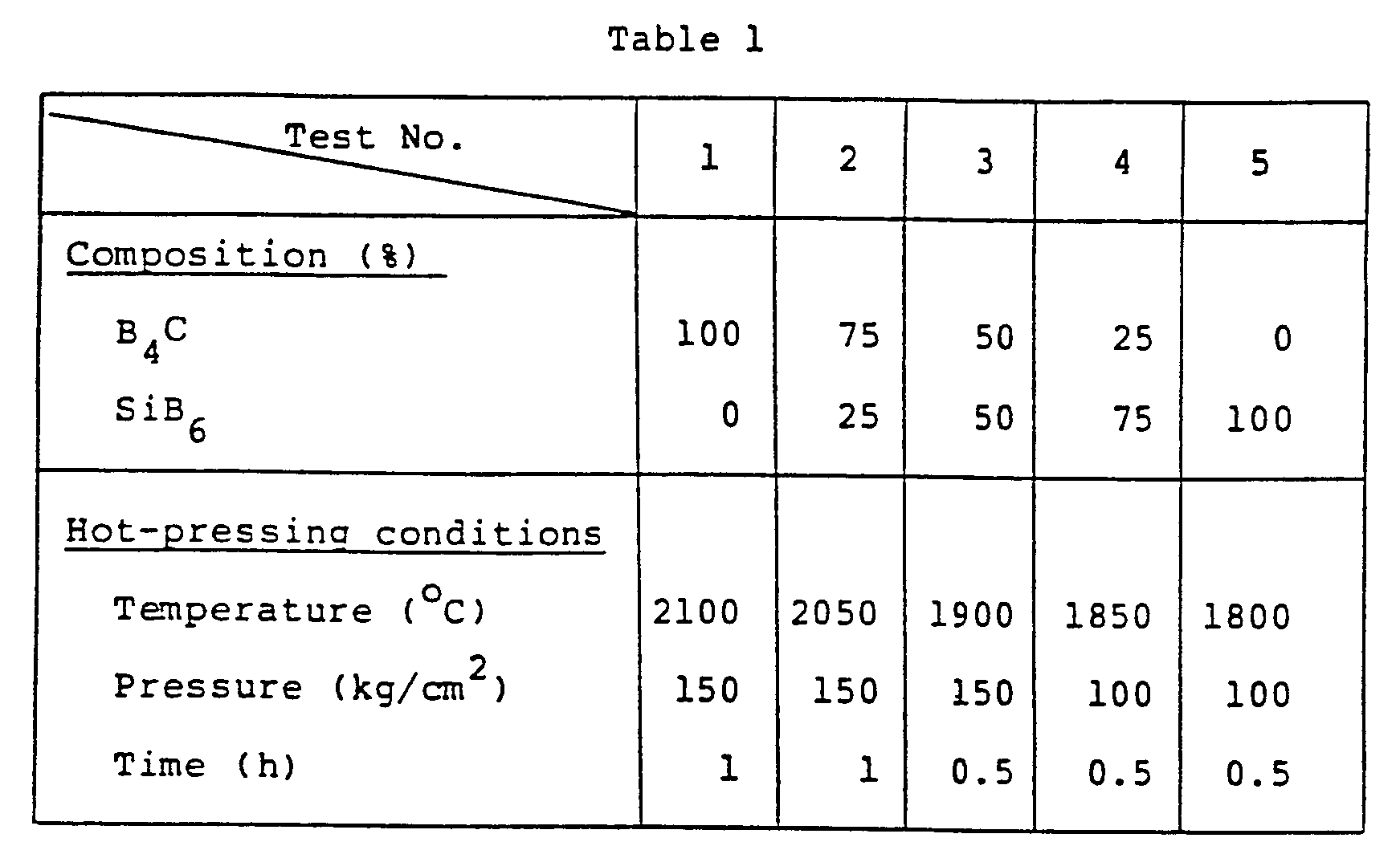
- By using such a needle-like electrode, a liquid metal ion source structure having the same structure as in Example 1, was prepared.
- Aluminum was melted in a boron nitride crucible under a vacuumed condition of 133,3 x 10⁻⁶ Pa (1 x 10⁻⁶ torr). While heating the needle-like electrode, it was dipped in the molten aluminum and 10 mg was pooled between the needle-like electrode and the reservoir. The needle-like electrode of the liquid metal ion source thus obtained, was heated to a temperature of 700°C, and the extraction of an ion beam was conducted, whereby an ion beam having a total current of 100 uA at an extraction voltage of -4 kV was stable over a period of 300 h (hours).
- With each of the needle-like electrodes prepared in Example 11, a liquid metal ion source holding 10 mg of an alloy comprising Ni, Pd, B and Be (atomic ratio of 30:60:8:2, respectively) was prepared. An ion beam of 100 pA at an extraction voltage of -5 kV was stable for 1000 h (hours) at a needle-like electrode temperature of 850°C.
- With each of the needle-like electrodes prepared in Example 11, a liquid metal ion source holding 10 mg of an alloy comprising Pt and As (atomic ratio of 70:30 respectively) was prepared. An ion beam of 50 pA at an extraction voltage of -7 kV was stable for 200 h (hours) at the needle-like electrode temperature of 800°C.
Claims (20)
Applications Claiming Priority (4)
| Application Number | Priority Date | Filing Date | Title |
|---|---|---|---|
| JP60119777A JPS61279042A (en) | 1985-06-04 | 1985-06-04 | Liquid metallic ion source composition |
| JP119777/85 | 1985-06-04 | ||
| JP281767/85 | 1985-12-14 | ||
| JP60281767A JPS62140340A (en) | 1985-12-14 | 1985-12-14 | Field emission type ion source |
Publications (3)
| Publication Number | Publication Date |
|---|---|
| EP0204297A2 EP0204297A2 (en) | 1986-12-10 |
| EP0204297A3 EP0204297A3 (en) | 1988-03-09 |
| EP0204297B1 true EP0204297B1 (en) | 1991-01-23 |
Family
ID=26457454
Family Applications (1)
| Application Number | Title | Priority Date | Filing Date |
|---|---|---|---|
| EP86107442A Expired EP0204297B1 (en) | 1985-06-04 | 1986-06-02 | Charged particle emission source structure |
Country Status (3)
| Country | Link |
|---|---|
| US (1) | US4721878A (en) |
| EP (1) | EP0204297B1 (en) |
| DE (1) | DE3677062D1 (en) |
Families Citing this family (46)
| Publication number | Priority date | Publication date | Assignee | Title |
|---|---|---|---|---|
| JP2528859B2 (en) * | 1987-02-27 | 1996-08-28 | 株式会社日立製作所 | Charged particle source |
| US4892752A (en) * | 1987-08-12 | 1990-01-09 | Oki Electric Industry Co., Ltd. | Method of ion implantation |
| EP0366851B1 (en) * | 1988-11-01 | 1994-02-16 | International Business Machines Corporation | Low-voltage source for narrow electron/ion beams |
| US5059859A (en) * | 1989-04-14 | 1991-10-22 | Hitachi, Ltd. | Charged particle beam generating apparatus of multi-stage acceleration type |
| JPH03133022A (en) * | 1989-10-16 | 1991-06-06 | Hitachi Ltd | Thermoelectric field radiation electron gun |
| JP4093590B2 (en) * | 1994-10-03 | 2008-06-04 | エフイーアイ カンパニー | Particle optical device comprising an electron source with extraction electrodes such as needles and diaphragms |
| US6815690B2 (en) * | 2002-07-23 | 2004-11-09 | Guardian Industries Corp. | Ion beam source with coated electrode(s) |
| US7074253B2 (en) * | 2003-05-20 | 2006-07-11 | Exxonmobil Research And Engineering Company | Advanced erosion resistant carbide cermets with superior high temperature corrosion resistance |
| US7175687B2 (en) * | 2003-05-20 | 2007-02-13 | Exxonmobil Research And Engineering Company | Advanced erosion-corrosion resistant boride cermets |
| US7438741B1 (en) | 2003-05-20 | 2008-10-21 | Exxonmobil Research And Engineering Company | Erosion-corrosion resistant carbide cermets for long term high temperature service |
| US7557358B2 (en) | 2003-10-16 | 2009-07-07 | Alis Corporation | Ion sources, systems and methods |
| US7504639B2 (en) * | 2003-10-16 | 2009-03-17 | Alis Corporation | Ion sources, systems and methods |
| US7557360B2 (en) * | 2003-10-16 | 2009-07-07 | Alis Corporation | Ion sources, systems and methods |
| US7521693B2 (en) * | 2003-10-16 | 2009-04-21 | Alis Corporation | Ion sources, systems and methods |
| US7485873B2 (en) * | 2003-10-16 | 2009-02-03 | Alis Corporation | Ion sources, systems and methods |
| US7368727B2 (en) * | 2003-10-16 | 2008-05-06 | Alis Technology Corporation | Atomic level ion source and method of manufacture and operation |
| US7518122B2 (en) | 2003-10-16 | 2009-04-14 | Alis Corporation | Ion sources, systems and methods |
| US7554097B2 (en) * | 2003-10-16 | 2009-06-30 | Alis Corporation | Ion sources, systems and methods |
| US7786451B2 (en) * | 2003-10-16 | 2010-08-31 | Alis Corporation | Ion sources, systems and methods |
| US7488952B2 (en) * | 2003-10-16 | 2009-02-10 | Alis Corporation | Ion sources, systems and methods |
| US7557359B2 (en) * | 2003-10-16 | 2009-07-07 | Alis Corporation | Ion sources, systems and methods |
| US7495232B2 (en) * | 2003-10-16 | 2009-02-24 | Alis Corporation | Ion sources, systems and methods |
| US8110814B2 (en) | 2003-10-16 | 2012-02-07 | Alis Corporation | Ion sources, systems and methods |
| US7601953B2 (en) * | 2006-03-20 | 2009-10-13 | Alis Corporation | Systems and methods for a gas field ion microscope |
| US7786452B2 (en) * | 2003-10-16 | 2010-08-31 | Alis Corporation | Ion sources, systems and methods |
| US7321118B2 (en) * | 2005-06-07 | 2008-01-22 | Alis Corporation | Scanning transmission ion microscope |
| US7557361B2 (en) * | 2003-10-16 | 2009-07-07 | Alis Corporation | Ion sources, systems and methods |
| US9159527B2 (en) * | 2003-10-16 | 2015-10-13 | Carl Zeiss Microscopy, Llc | Systems and methods for a gas field ionization source |
| US7414243B2 (en) * | 2005-06-07 | 2008-08-19 | Alis Corporation | Transmission ion microscope |
| US7511280B2 (en) * | 2003-10-16 | 2009-03-31 | Alis Corporation | Ion sources, systems and methods |
| US7511279B2 (en) * | 2003-10-16 | 2009-03-31 | Alis Corporation | Ion sources, systems and methods |
| US7554096B2 (en) * | 2003-10-16 | 2009-06-30 | Alis Corporation | Ion sources, systems and methods |
| EP1622184B1 (en) * | 2004-07-28 | 2011-05-18 | ICT Integrated Circuit Testing Gesellschaft für Halbleiterprüftechnik mbH | Emitter for an ion source and method of producing same |
| GB2424754A (en) * | 2005-03-29 | 2006-10-04 | Univ Basel | A focused ion beam generator |
| US20070116373A1 (en) * | 2005-11-23 | 2007-05-24 | Sonosite, Inc. | Multi-resolution adaptive filtering |
| US7731776B2 (en) * | 2005-12-02 | 2010-06-08 | Exxonmobil Research And Engineering Company | Bimodal and multimodal dense boride cermets with superior erosion performance |
| WO2007109666A2 (en) * | 2006-03-20 | 2007-09-27 | Alis Corporation | Systems and methods for a helium ion pump |
| US8080930B2 (en) * | 2006-09-07 | 2011-12-20 | Michigan Technological University | Self-regenerating nanotips for low-power electric propulsion (EP) cathodes |
| US7804068B2 (en) * | 2006-11-15 | 2010-09-28 | Alis Corporation | Determining dopant information |
| WO2009067178A1 (en) * | 2007-11-20 | 2009-05-28 | Exxonmobil Research And Engineering Company | Bimodal and multimodal dense boride cermets with low melting point binder |
| US8022609B2 (en) * | 2008-06-24 | 2011-09-20 | Hermes-Microvision, Inc. | Thermal field emission cathode |
| US9105434B2 (en) * | 2011-05-04 | 2015-08-11 | The Board Of Regents Of The Nevada System Of Higher Education On Behalf Of The University Of Nevada, Las Vegas | High current, high energy beam focusing element |
| US9418827B2 (en) * | 2013-07-23 | 2016-08-16 | Hamilton Sundstrand Corporation | Methods of ion source fabrication |
| KR20190032592A (en) * | 2016-08-08 | 2019-03-27 | 에이에스엠엘 네델란즈 비.브이. | Electronic emitter and its manufacturing method |
| US11295925B2 (en) * | 2019-07-23 | 2022-04-05 | Param Corporation | Electron gun device |
| JP7573457B2 (en) * | 2021-02-25 | 2024-10-25 | 株式会社ニューフレアテクノロジー | Cathode mechanism of electron gun, electron gun, and electron beam writing device |
Family Cites Families (8)
| Publication number | Priority date | Publication date | Assignee | Title |
|---|---|---|---|---|
| US3814975A (en) * | 1969-08-06 | 1974-06-04 | Gen Electric | Electron emission system |
| GB1574611A (en) * | 1976-04-13 | 1980-09-10 | Atomic Energy Authority Uk | Ion sources |
| JPS583579B2 (en) * | 1980-02-12 | 1983-01-21 | 工業技術院長 | ion source device |
| JPS57132632A (en) * | 1981-02-09 | 1982-08-17 | Hitachi Ltd | Ion source |
| JPS57196443A (en) * | 1981-05-29 | 1982-12-02 | Denki Kagaku Kogyo Kk | Manufacture of hot cathode |
| JPS5835829A (en) * | 1981-08-28 | 1983-03-02 | Jeol Ltd | Metal ion source |
| JPS5838906B2 (en) * | 1981-09-03 | 1983-08-26 | 日本電子株式会社 | metal ion source |
| JPS59101750A (en) * | 1982-12-01 | 1984-06-12 | Hitachi Ltd | Liquid metal ion source |
-
1986
- 1986-06-02 DE DE8686107442T patent/DE3677062D1/en not_active Expired - Lifetime
- 1986-06-02 EP EP86107442A patent/EP0204297B1/en not_active Expired
- 1986-06-04 US US06/870,530 patent/US4721878A/en not_active Expired - Fee Related
Also Published As
| Publication number | Publication date |
|---|---|
| DE3677062D1 (en) | 1991-02-28 |
| EP0204297A2 (en) | 1986-12-10 |
| US4721878A (en) | 1988-01-26 |
| EP0204297A3 (en) | 1988-03-09 |
Similar Documents
| Publication | Publication Date | Title |
|---|---|---|
| US4721878A (en) | Charged particle emission source structure | |
| US4467240A (en) | Ion beam source | |
| WO1987003739A1 (en) | Liquid metal ion source | |
| US4482839A (en) | Thermionic emission cathode and preparation thereof | |
| KR900004762B1 (en) | Impregnated cathode | |
| US4701769A (en) | Thermal head and method for fabrication thereof | |
| US3645786A (en) | Method for depositing on a support a thin layer of a solid ceramic electrolyte for a fuel cell | |
| US4438153A (en) | Method of and apparatus for the vapor deposition of material upon a substrate | |
| CN100550269C (en) | X-ray tube cathode assembly and interface reaction connecting process | |
| JPH026184B2 (en) | ||
| US4629931A (en) | Liquid metal ion source | |
| JP2517678B2 (en) | Liquid metal ion source | |
| JPH0676730A (en) | Thermionic emission cathode | |
| JPS62140340A (en) | Field emission type ion source | |
| JP5047062B2 (en) | Thermionic emission cathode | |
| JPH0566698B2 (en) | ||
| JPH02247951A (en) | Electric field-discharge type ion source | |
| JP2510719B2 (en) | Liquid metal ion source structure | |
| JPH02250238A (en) | Liquid metal ion source | |
| JP2025144131A (en) | Electron source, manufacturing method thereof, and electron beam device | |
| JPS5840743A (en) | Metal ion source | |
| JPH03233826A (en) | Field emission type ion source | |
| JPH04322029A (en) | Impregnated type cathode and manufacture thereof | |
| JPS63221541A (en) | Liquid metal ion source | |
| JPH0317795B2 (en) |
Legal Events
| Date | Code | Title | Description |
|---|---|---|---|
| PUAI | Public reference made under article 153(3) epc to a published international application that has entered the european phase |
Free format text: ORIGINAL CODE: 0009012 |
|
| AK | Designated contracting states |
Kind code of ref document: A2 Designated state(s): DE GB NL |
|
| PUAL | Search report despatched |
Free format text: ORIGINAL CODE: 0009013 |
|
| AK | Designated contracting states |
Kind code of ref document: A3 Designated state(s): DE GB NL |
|
| 17P | Request for examination filed |
Effective date: 19880608 |
|
| 17Q | First examination report despatched |
Effective date: 19890517 |
|
| GRAA | (expected) grant |
Free format text: ORIGINAL CODE: 0009210 |
|
| AK | Designated contracting states |
Kind code of ref document: B1 Designated state(s): DE GB NL |
|
| REF | Corresponds to: |
Ref document number: 3677062 Country of ref document: DE Date of ref document: 19910228 |
|
| PLBE | No opposition filed within time limit |
Free format text: ORIGINAL CODE: 0009261 |
|
| STAA | Information on the status of an ep patent application or granted ep patent |
Free format text: STATUS: NO OPPOSITION FILED WITHIN TIME LIMIT |
|
| 26N | No opposition filed | ||
| PGFP | Annual fee paid to national office [announced via postgrant information from national office to epo] |
Ref country code: GB Payment date: 19980526 Year of fee payment: 13 |
|
| PGFP | Annual fee paid to national office [announced via postgrant information from national office to epo] |
Ref country code: DE Payment date: 19980608 Year of fee payment: 13 |
|
| PGFP | Annual fee paid to national office [announced via postgrant information from national office to epo] |
Ref country code: NL Payment date: 19980629 Year of fee payment: 13 |
|
| PG25 | Lapsed in a contracting state [announced via postgrant information from national office to epo] |
Ref country code: GB Free format text: LAPSE BECAUSE OF NON-PAYMENT OF DUE FEES Effective date: 19990602 |
|
| PG25 | Lapsed in a contracting state [announced via postgrant information from national office to epo] |
Ref country code: NL Free format text: LAPSE BECAUSE OF NON-PAYMENT OF DUE FEES Effective date: 20000101 |
|
| GBPC | Gb: european patent ceased through non-payment of renewal fee |
Effective date: 19990602 |
|
| NLV4 | Nl: lapsed or anulled due to non-payment of the annual fee |
Effective date: 20000101 |
|
| PG25 | Lapsed in a contracting state [announced via postgrant information from national office to epo] |
Ref country code: DE Free format text: LAPSE BECAUSE OF NON-PAYMENT OF DUE FEES Effective date: 20000503 |