EP0203123B1 - Trepan a rouleau de coupe a fonctionnement radial a percussion, supporte en rotation sur un excentrique rotatif - Google Patents
Trepan a rouleau de coupe a fonctionnement radial a percussion, supporte en rotation sur un excentrique rotatif Download PDFInfo
- Publication number
- EP0203123B1 EP0203123B1 EP85905805A EP85905805A EP0203123B1 EP 0203123 B1 EP0203123 B1 EP 0203123B1 EP 85905805 A EP85905805 A EP 85905805A EP 85905805 A EP85905805 A EP 85905805A EP 0203123 B1 EP0203123 B1 EP 0203123B1
- Authority
- EP
- European Patent Office
- Prior art keywords
- roller
- eccentric
- rollers
- cog
- milling
- Prior art date
- Legal status (The legal status is an assumption and is not a legal conclusion. Google has not performed a legal analysis and makes no representation as to the accuracy of the status listed.)
- Expired - Lifetime
Links
- 238000005553 drilling Methods 0.000 claims description 9
- 238000003801 milling Methods 0.000 claims description 5
- 239000011435 rock Substances 0.000 claims description 3
- 239000011796 hollow space material Substances 0.000 claims 1
- 238000010009 beating Methods 0.000 description 2
- 238000000227 grinding Methods 0.000 description 2
- 239000002184 metal Substances 0.000 description 2
- 238000007789 sealing Methods 0.000 description 2
- 230000005540 biological transmission Effects 0.000 description 1
- 230000001419 dependent effect Effects 0.000 description 1
- 230000005284 excitation Effects 0.000 description 1
- 239000007788 liquid Substances 0.000 description 1
- 238000005096 rolling process Methods 0.000 description 1
Images
Classifications
-
- B—PERFORMING OPERATIONS; TRANSPORTING
- B23—MACHINE TOOLS; METAL-WORKING NOT OTHERWISE PROVIDED FOR
- B23C—MILLING
- B23C5/00—Milling-cutters
-
- B—PERFORMING OPERATIONS; TRANSPORTING
- B23—MACHINE TOOLS; METAL-WORKING NOT OTHERWISE PROVIDED FOR
- B23C—MILLING
- B23C3/00—Milling particular work; Special milling operations; Machines therefor
-
- B—PERFORMING OPERATIONS; TRANSPORTING
- B23—MACHINE TOOLS; METAL-WORKING NOT OTHERWISE PROVIDED FOR
- B23D—PLANING; SLOTTING; SHEARING; BROACHING; SAWING; FILING; SCRAPING; LIKE OPERATIONS FOR WORKING METAL BY REMOVING MATERIAL, NOT OTHERWISE PROVIDED FOR
- B23D1/00—Planing or slotting machines cutting by relative movement of the tool and workpiece in a horizontal straight line only
- B23D1/20—Planing or slotting machines cutting by relative movement of the tool and workpiece in a horizontal straight line only with tool-supports or work-supports specially mounted or guided for working in different directions or at different angles; Special purpose machines
- B23D1/26—Planing or slotting machines cutting by relative movement of the tool and workpiece in a horizontal straight line only with tool-supports or work-supports specially mounted or guided for working in different directions or at different angles; Special purpose machines for planing edges or ridges or cutting grooves
-
- B—PERFORMING OPERATIONS; TRANSPORTING
- B28—WORKING CEMENT, CLAY, OR STONE
- B28D—WORKING STONE OR STONE-LIKE MATERIALS
- B28D1/00—Working stone or stone-like materials, e.g. brick, concrete or glass, not provided for elsewhere; Machines, devices, tools therefor
- B28D1/18—Working stone or stone-like materials, e.g. brick, concrete or glass, not provided for elsewhere; Machines, devices, tools therefor by milling, e.g. channelling by means of milling tools
-
- B—PERFORMING OPERATIONS; TRANSPORTING
- B28—WORKING CEMENT, CLAY, OR STONE
- B28D—WORKING STONE OR STONE-LIKE MATERIALS
- B28D1/00—Working stone or stone-like materials, e.g. brick, concrete or glass, not provided for elsewhere; Machines, devices, tools therefor
- B28D1/26—Working stone or stone-like materials, e.g. brick, concrete or glass, not provided for elsewhere; Machines, devices, tools therefor by impact tools, e.g. by chisels or other tools having a cutting edge
Definitions
- the invention relates to a device for radial hammering, drilling and milling in hard rock and the like according to the preamble of claim 1.
- First the first transmission is activated.
- a worm meshes with a gear, whereby another gear rotates eccentrically in a third gear. This causes a spindle to rotate, at the end of which the milling tool is seated.
- This first gear is therefore only intended to generate the self-rotation of the tool.
- the spindle sits eccentrically in a spindle carrier, which is set in rotation by the second gear. Since the spindle sits eccentrically in the spindle carrier, the spindle axis executes a circular movement that is superimposed on the self-rotation of the spindle. With the help of the tool, a recess or an undercut is made in the metal workpiece, the dimensions of which depend on the eccentricity of the spindle axis in the spindle carrier.
- the rotary movements of the tool or the spindle must be relatively slow, otherwise the tool fixed on the spindle, which is fixed in terms of rotation, is quickly destroyed during the circular movement and the workpiece is rendered unusable.
- the invention is based on roller drilling tools that achieve unbalanced or linear excitation with the lowest pressures, high drilling progress in hard rock and the like.
- a disadvantage of these tools is that undesirable vibration problems occur.
- these drilling tools are technically very complex and have an unfavorable energy balance.
- the invention is therefore based on the object of a device of the type mentioned train that it is comparatively simple and robust, but unwanted vibrations are largely excluded.
- a drilling roller which can be independently rolling or driven, is rotatably mounted on a cam, in a comparatively simple and robust manner, with the possibility of various variations.
- the device held on one or two sides can be balanced or unbalanced.
- the device can also drill holes and slots individually (or when two devices are combined to form a twin), rotated together, continuously or intermittently.
- the eccentric When the shaft rotates, the eccentric also rotates (e.g. at 4000 revolutions per minute). Thus, the roll hits 4000 times a minute. Since the roller is mounted on the eccentric and is connected to the internally toothed gear, which is eccentric on the externally toothed gear running, the roller rotates extremely slowly (e.g. at 200 revolutions per minute). The gears thus act like a reduction gear. The beating movement of the roll is overlaid by a slow grinding movement. If necessary, the blows are superimposed or amplified by unbalance or other impact pulses.
- the high-speed eccentric in particular, is provided with additional flywheel / balancing mass to increase the counter torque or the impact force.
- a cavity can be provided in the eccentric, which can be filled with a liquid, for example.
- rollers in parallel next to each other, each of which is mounted on an eccentric.
- the rollers each have a separate eccentric drive or a drive shaft, whereby they operate unbalanced or balanced, in the same direction or in different directions of rotation.
- the two roles can each have their own drive. However, you can also use z. B. a double crank pin.
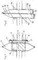
- reference numeral 1 designates a rotating and rotating drilling and cutting roller.
- the roller 1 is rotatably mounted on an eccentric 2, which is driven by a suitable drive source such as a motor through the shaft 4, which is surrounded by a stationary housing 3.
- An inner gear 5 is attached to the housing and remains stationary with the housing.
- the inner gear 5 is arranged concentrically to the shaft 4 and has an outer toothing which meshes with the inner toothing of a larger ring gear 7.
- a sealing washer 6 with a sealing lip is provided.
- the ring gear 7 is attached to the roller 1, the two rotating simultaneously.
- the inner diameter of the ring gear 7 is larger than the outer diameter of the inner gear 5.
- the eccentric 2 is provided with a cavity 8 which, as a counterbalance for balanced rotation z. B. can be filled with an unbalanced mass.
- 9 and 10 denote the boring rollers rotatably mounted on eccentrics (not shown), the boring rollers 9 and 10 each having their own eccentric drive, which operate either in the same direction of rotation or in opposite directions.
- brackets or bearings are designated, which are either rigidly connected to each other, or can be held together or individually elastic or spring.
- roller drilling tools are shown, which are provided with tapered blades.
- the roller tools designated 15 are wider. These tools 15 are suitable for free cutting (see 16).
- the two eccentrics can be connected with the same direction of rotation and the same speed by means of a double crank pin 17.
- screw connections can also be provided, or two or more eccentrics from one piece, which are balanced.
- Another alternative is to make an eccentric shaft hollow for carrying out the drive to the other eccentric.
- bearings can be provided to enable a one-sided drive, possibly with a one-sided bearing or holder.
- the operation of the device according to FIG. 1 is as follows: When the shaft 4 rotates, the eccentric 2 also rotates (e.g. at 4000 revolutions per minute). Thus the roll hits 1 4000 times a minute. Since the roller is mounted on the eccentric and is connected to the internally toothed gear 7, which rotates eccentrically on the externally toothed gear 5, the roller 1 rotates extremely slowly (e.g. at 200 revolutions per minute). Thus, the gears 7 and 5 act like a reduction gear. The beating movement of the roller 1 is due to a slow grinding movement overlaid.
- the gears can alternatively either function as a freewheel or as a ratchet to prevent the drilling rollers from running in the direction of rotation of the eccentrics.
Landscapes
- Engineering & Computer Science (AREA)
- Mechanical Engineering (AREA)
- Mining & Mineral Resources (AREA)
- Earth Drilling (AREA)
Abstract
Claims (13)
- Dispositif pour assurer un effet de percussion radiale, de forage et de fraisage dans une roche dure ou analogue, au moyen d'au moins un galet (1) entraîné par un organe moteur et comportant sur sa périphérie des outils d'attaque, ce galet (1) étant soumis, outre sa rotation propre, à un mouvement de révolution sensiblement circulaire suivant un axe parallèle à son axe de rotation, caractérisé en ce que le galet (1) est monté libre en rotation sur un excentrique (2) lui-même calé sur un arbre (4) monté sur des paliers fixés à un carter (3), le mouvement de fraisage du galet (1) étant assuré par une couronne à denture intérieure (7) dans laquelle une roue dentée (5) de plus petit diamètre et à denture externe effectue un mouvement tournant excentré par rapport à la couronne dentée (7), 1'une des roues dentées (5,7) étant solidaire en rotation du carter (3) alors que l'autre roue dentée (5,7) est solidaire en rotation du galet (1).
- Dispositif selon la revendication 1, caractérisé en ce que la couronne à denture interne (7) est fixée au galet (1), alors que l'autre roue dentée (5), à denture externe, est fixée au carter (3).
- Dispositif selon la revendication 1 ou 2, caractérisé en ce que les deux roues dentées (5,7) sont montées folles en rotation.
- Dispositif selon la revendication 1 ou 2, caractérisé en ce que les deux roues dentées (5,7) sont associées à un cliquet autorisant un seul sens de rotation.
- Dispositif selon l'une des revendications 1 à 4, caractérisé en ce que l'excentrique (2) comporte des moyens (8) assurant un effet de balourd.
- Dispositif selon la revendication 5, caractérisé en ce que l'excentrique (2) comporte une cavité (8) pour recevoir une masse de déséquilibrage.
- Dispositif selon l'une des revendications 1 à 6, caractérisé en ce qu'il comporte deux galets montés parallèlement côte à côte, et en ce que les excentriques (2) auxquels sont associés les galets sont montés avec un décalage relatif de 180 degrés, et prévus pour être entraînés en rotation synchrone dans le même sens.
- Dispositif selon l'une des revendications 1 à 6, caractérisé en ce que les deux galets (1) sont disposés parallèlement côte à côte, et en ce que les excentriques (2) sur lesquels sont disposés les galets sont montés avec un décalage relatif de 180 degrés, et prévus pour être entraînés en rotation synchrone en sens opposés.
- Dispositif selon la revendication 7 ou 8, caractérisé en ce que chaque galet (1) est prévu pour être entraîné séparément au moyen des roues dentées (5,7).
- Dispositif selon la revendication 7 ou 8, caractérisé en ce que l'un des galets (1) est prévu pour être entraîné au moyen des roues dentées (5,7), tandis que l'excentrique (2) de l'autre galet (1) est relié à l'excentrique du premier galet par un arbre à double vilebrequin (17).
- Dispositif selon l'une des revendications 7 à 10, caractérisé en ce que les carters(3) auxquels sont associés les galets (1) sont rigidement reliés l'un à l'autre.
- Dispositif selon l'une des revendications 1 à 11, caractérisé en ce qu'il comporte des paliers élastiques, montés sur ressorts.
- Dispositif selon l'une des revendications 1 à 12, caractérisé en ce que les outils d'attaque montés à la périphérie des galets (1) sont interchangeables.
Priority Applications (1)
| Application Number | Priority Date | Filing Date | Title |
|---|---|---|---|
| AT85905805T ATE61954T1 (de) | 1984-11-10 | 1985-11-07 | Radial schlagendes rollen-/fraes-bohrwerkzeug auf einem angetriebenen rotierenden exzenter drehend gelagert. |
Applications Claiming Priority (2)
| Application Number | Priority Date | Filing Date | Title |
|---|---|---|---|
| CH5503/84 | 1984-11-10 | ||
| CH550384 | 1984-11-10 |
Publications (2)
| Publication Number | Publication Date |
|---|---|
| EP0203123A1 EP0203123A1 (fr) | 1986-12-03 |
| EP0203123B1 true EP0203123B1 (fr) | 1991-03-27 |
Family
ID=4294707
Family Applications (1)
| Application Number | Title | Priority Date | Filing Date |
|---|---|---|---|
| EP85905805A Expired - Lifetime EP0203123B1 (fr) | 1984-11-10 | 1985-11-07 | Trepan a rouleau de coupe a fonctionnement radial a percussion, supporte en rotation sur un excentrique rotatif |
Country Status (5)
| Country | Link |
|---|---|
| EP (1) | EP0203123B1 (fr) |
| AU (1) | AU591472B2 (fr) |
| DE (1) | DE3582327D1 (fr) |
| WO (1) | WO1986002865A1 (fr) |
| ZA (1) | ZA858633B (fr) |
Families Citing this family (1)
| Publication number | Priority date | Publication date | Assignee | Title |
|---|---|---|---|---|
| CH678706A5 (fr) * | 1987-08-31 | 1991-10-31 | Bechem Hannelore |
Family Cites Families (4)
| Publication number | Priority date | Publication date | Assignee | Title |
|---|---|---|---|---|
| US1744857A (en) * | 1926-12-10 | 1930-01-28 | Cincinnati Milling Machine Co | Milling machine |
| GB571388A (en) * | 1944-01-06 | 1945-08-22 | Ernst Carstens | Improvements in devices for working relatively soft materials |
| US4016741A (en) * | 1975-12-29 | 1977-04-12 | Sitter Spencer B | Bracelet domer |
| DE3105396A1 (de) * | 1981-02-14 | 1982-10-21 | Friedhelm 4600 Dortmund Heymann | Vorrichtung zur bearbeitung der oberflaeche von unregelmaessige konturen aufweisenden koerpern |
-
1985
- 1985-11-07 EP EP85905805A patent/EP0203123B1/fr not_active Expired - Lifetime
- 1985-11-07 WO PCT/EP1985/000591 patent/WO1986002865A1/fr active IP Right Grant
- 1985-11-07 AU AU51991/86A patent/AU591472B2/en not_active Ceased
- 1985-11-07 DE DE8585905805T patent/DE3582327D1/de not_active Expired - Fee Related
- 1985-11-11 ZA ZA858633A patent/ZA858633B/xx unknown
Also Published As
| Publication number | Publication date |
|---|---|
| AU591472B2 (en) | 1989-12-07 |
| AU5199186A (en) | 1986-06-03 |
| ZA858633B (en) | 1986-10-29 |
| EP0203123A1 (fr) | 1986-12-03 |
| DE3582327D1 (de) | 1991-05-02 |
| WO1986002865A1 (fr) | 1986-05-22 |
Similar Documents
| Publication | Publication Date | Title |
|---|---|---|
| EP1841949B1 (fr) | Dispositif de fraisage de pierres et d'autres materiaux et procede de fraisage de pierres et similaires faisant intervenir ledit dispositif | |
| CH672908A5 (fr) | ||
| CH677890A5 (de) | Exzenterantrieb fuer bohrwerkzeuge. | |
| EP0455994A2 (fr) | Entraînement excentrique pour rouleaux, molettes et outils de forage, fraiseurs à oscillation latérale | |
| EP1734224B1 (fr) | Dispositif d'entraînement pour outils rotatifs à mouvement oscillatoire superposé et outil correspondant | |
| EP0563766B1 (fr) | Broche d'outil, en particulier broche de perçage | |
| EP0203123B1 (fr) | Trepan a rouleau de coupe a fonctionnement radial a percussion, supporte en rotation sur un excentrique rotatif | |
| WO2023099300A1 (fr) | Dispositif de broyage en particulier de roche et d'autres matériaux | |
| DE2330186A1 (de) | Vorrichtung zum formen von epitrochoidenfoermigen oberflaechen | |
| DE3301671C2 (fr) | ||
| DE8808679U1 (de) | Schleifkopf zum Oberflächenbearbeiten und Polieren von Stein, Marmor und anderen harten Werkstoffen | |
| EP0592981B1 (fr) | Outils oscillants et balancés au moyen de contre-poids | |
| EP0330683A1 (fr) | Trepan a taillant ou a molettes | |
| DE2448753C2 (de) | Schneidkopf fur Vortriebs- und Gewinnungsmaschinen im Berg- und Tunnelbau | |
| DE10348801B3 (de) | Spindelanordnung für ein radial zustellbares, rotierendes Werkzeug | |
| DE207092C (fr) | ||
| DE4036193A1 (de) | Exzenterantrieb fuer radial schwingende walzen-, rollen- und fraesbohrwerkzeuge | |
| DE2310595A1 (de) | Vorrichtung zum abrunden der stirnseitigen enden der zaehne von verzahnten koerpern | |
| WO1989001837A1 (fr) | Rouleaux, billes rotatifs ou similaires radialement percutants pour le deblayage/fraisage de rochers ou d'autres materiaux | |
| CH633466A5 (de) | Drehmeissel. | |
| CH719941A2 (de) | Felsbohrvorrichtung und Verfahren zum Betreiben derselben. | |
| DE2221576C3 (de) | Werkzeug zum Schleifen, Honen und dgl. von trochoidenförmigen Mantelflächen | |
| WO2014108496A1 (fr) | Dispositif de transmission | |
| DE2047442A1 (de) | Bohrmaschine | |
| DE239481C (fr) |
Legal Events
| Date | Code | Title | Description |
|---|---|---|---|
| PUAI | Public reference made under article 153(3) epc to a published international application that has entered the european phase |
Free format text: ORIGINAL CODE: 0009012 |
|
| AK | Designated contracting states |
Kind code of ref document: A1 Designated state(s): AT BE CH DE FR GB IT LI LU NL SE |
|
| 17P | Request for examination filed |
Effective date: 19870116 |
|
| 17Q | First examination report despatched |
Effective date: 19881010 |
|
| GRAA | (expected) grant |
Free format text: ORIGINAL CODE: 0009210 |
|
| AK | Designated contracting states |
Kind code of ref document: B1 Designated state(s): AT BE CH DE FR GB IT LI LU NL SE |
|
| REF | Corresponds to: |
Ref document number: 61954 Country of ref document: AT Date of ref document: 19910415 Kind code of ref document: T |
|
| ITF | It: translation for a ep patent filed | ||
| ET | Fr: translation filed | ||
| GBT | Gb: translation of ep patent filed (gb section 77(6)(a)/1977) | ||
| REF | Corresponds to: |
Ref document number: 3582327 Country of ref document: DE Date of ref document: 19910502 |
|
| PG25 | Lapsed in a contracting state [announced via postgrant information from national office to epo] |
Ref country code: SE Effective date: 19911108 |
|
| PG25 | Lapsed in a contracting state [announced via postgrant information from national office to epo] |
Ref country code: LU Free format text: LAPSE BECAUSE OF NON-PAYMENT OF DUE FEES Effective date: 19911130 Ref country code: BE Effective date: 19911130 |
|
| PLBE | No opposition filed within time limit |
Free format text: ORIGINAL CODE: 0009261 |
|
| STAA | Information on the status of an ep patent application or granted ep patent |
Free format text: STATUS: NO OPPOSITION FILED WITHIN TIME LIMIT |
|
| 26N | No opposition filed | ||
| BERE | Be: lapsed |
Owner name: PETERS A.G. Effective date: 19911130 |
|
| PG25 | Lapsed in a contracting state [announced via postgrant information from national office to epo] |
Ref country code: NL Effective date: 19920601 |
|
| NLV4 | Nl: lapsed or anulled due to non-payment of the annual fee | ||
| PG25 | Lapsed in a contracting state [announced via postgrant information from national office to epo] |
Ref country code: FR Effective date: 19920731 |
|
| REG | Reference to a national code |
Ref country code: CH Ref legal event code: PL |
|
| REG | Reference to a national code |
Ref country code: FR Ref legal event code: ST |
|
| REG | Reference to a national code |
Ref country code: CH Ref legal event code: AEN |
|
| EUG | Se: european patent has lapsed |
Ref document number: 85905805.9 Effective date: 19920604 |
|
| REG | Reference to a national code |
Ref country code: CH Ref legal event code: PUE Owner name: HANNELORE BECHEM |
|
| REG | Reference to a national code |
Ref country code: CH Ref legal event code: PL |
|
| REG | Reference to a national code |
Ref country code: CH Ref legal event code: AEN Free format text: DAS PATENT IST AUFGRUND DES WEITERBEHANDLUNGSANTRAGS VOM 27.08.1996 REAKTIVIERT WORDEN. |
|
| REG | Reference to a national code |
Ref country code: GB Ref legal event code: IF02 |
|
| PGFP | Annual fee paid to national office [announced via postgrant information from national office to epo] |
Ref country code: DE Payment date: 20020131 Year of fee payment: 17 |
|
| PGFP | Annual fee paid to national office [announced via postgrant information from national office to epo] |
Ref country code: GB Payment date: 20021106 Year of fee payment: 18 |
|
| PGFP | Annual fee paid to national office [announced via postgrant information from national office to epo] |
Ref country code: AT Payment date: 20021118 Year of fee payment: 18 |
|
| PGFP | Annual fee paid to national office [announced via postgrant information from national office to epo] |
Ref country code: CH Payment date: 20030303 Year of fee payment: 18 |
|
| PG25 | Lapsed in a contracting state [announced via postgrant information from national office to epo] |
Ref country code: DE Free format text: LAPSE BECAUSE OF NON-PAYMENT OF DUE FEES Effective date: 20030603 |
|
| PG25 | Lapsed in a contracting state [announced via postgrant information from national office to epo] |
Ref country code: GB Free format text: LAPSE BECAUSE OF NON-PAYMENT OF DUE FEES Effective date: 20031107 Ref country code: AT Free format text: LAPSE BECAUSE OF NON-PAYMENT OF DUE FEES Effective date: 20031107 |
|
| PG25 | Lapsed in a contracting state [announced via postgrant information from national office to epo] |
Ref country code: LI Free format text: LAPSE BECAUSE OF NON-PAYMENT OF DUE FEES Effective date: 20031130 Ref country code: CH Free format text: LAPSE BECAUSE OF NON-PAYMENT OF DUE FEES Effective date: 20031130 |
|
| GBPC | Gb: european patent ceased through non-payment of renewal fee |
Effective date: 20031107 |
|
| REG | Reference to a national code |
Ref country code: CH Ref legal event code: PL |