EP0202561B1 - Ironing apparatus - Google Patents
Ironing apparatus Download PDFInfo
- Publication number
- EP0202561B1 EP0202561B1 EP86106374A EP86106374A EP0202561B1 EP 0202561 B1 EP0202561 B1 EP 0202561B1 EP 86106374 A EP86106374 A EP 86106374A EP 86106374 A EP86106374 A EP 86106374A EP 0202561 B1 EP0202561 B1 EP 0202561B1
- Authority
- EP
- European Patent Office
- Prior art keywords
- soleplate
- ironing device
- sole plate
- ironing
- air stream
- Prior art date
- Legal status (The legal status is an assumption and is not a legal conclusion. Google has not performed a legal analysis and makes no representation as to the accuracy of the status listed.)
- Expired
Links
Images
Classifications
-
- D—TEXTILES; PAPER
- D06—TREATMENT OF TEXTILES OR THE LIKE; LAUNDERING; FLEXIBLE MATERIALS NOT OTHERWISE PROVIDED FOR
- D06F—LAUNDERING, DRYING, IRONING, PRESSING OR FOLDING TEXTILE ARTICLES
- D06F75/00—Hand irons
- D06F75/30—Hand irons of special external shape or form
Definitions
- the invention relates to a device for ironing a textile material lying on a base, in which an airflow generated by a blower and led via a flow channel to at least one outlet opening in the soleplate emerges from a soleplate of the ironing device.
- an iron which has a compressor which generates an air flow. Outlet openings for the air flow are provided on the underside of the ironing plate at the edge of the ironing plate.
- the air flow generated by the compressor flows in the iron through flow channels in which the air flow is heated.
- the hot air stream emerging from the outlet openings is deflected by the textile material placed on the base, flows radially away from the iron in all directions and serves to dry and smooth the textile material to be ironed. The warm air is thus distributed along the outline of the iron.
- the advantage that the drying effect of the warm air flow may achieve is reduced by the reduced pressure of the ironing plate on the textile material.
- the iron according to DE-OS-2 224 780 therefore requires significantly larger amounts of energy for ironing than a conventional iron.
- JP-GM-4 821 008 discloses a hair dryer which can also be used as an iron and has outlet openings in the ironing plate. Warm air flows from the outlet openings, which air is generated in that air is sucked in by a fan having a rotor via an opening provided on the front wall of the iron of the iron and is fed to the openings contained in the ironing plate via a first heating device. If the rotor is operated in the opposite direction of rotation and the device is not in contact with a textile material for the purpose of ironing, air flows in via the openings in the ironing plate, which is then heated in a second heating device and at the front of the Device opening emerges. With this direction of rotation of the rotor, the device serves as a hair dryer. Apart from the fact that this device is relatively complicated due to its two heating devices, it also remains in contact with the textile material to be ironed when ironing. h that the user has to exert considerable effort when ironing.
- the task was to design the ironing device from simple parts and inexpensive to assemble.
- blower is contained in a hair dryer which can be coupled to the soleplate and in that an edge bead directed onto the textile material is formed on the soleplate.
- the ironing device there is no direct contact with the textile material to be ironed over the entire sole plate.
- the ironing effect is therefore based on the flow of the air cushion carrying the ironing device and can therefore take place without contact heat.
- the air stream emerging from the outlet opening thus serves to carry the ironing device and to expel the moisture from the textile material. Furthermore, it is not necessary to process the sole plate particularly smoothly since the sliding friction between the soleplate and the textile material is eliminated. In addition, there is no risk of fire from the soleplate.
- the ironing device hovers on the air cushion, the weight of the iron is transferred to the textile material to be ironed via the large air cushion.
- the smoothing effect of the weight of the ironing device is not lost, although the adverse friction between the sole plate and textile material is avoided.
- the air flow is guided over long flow paths under the sole plate.
- the pressure of the air flow is selected so that a sufficient static pressure is established between the sole plate and the textile material, which is sufficient to lift the ironing device a certain distance from the textile material.
- the ironing device according to the invention has an edge bead on the soleplate.
- the edge bead creates a delimited storage space for the air flow under the sole plate.
- the edge bead hinders the outflow of the air flow and contributes to the fact that the air cushion or air cushion effect is increased at lower blower outputs.
- a warm air flow is used, whereby a similar effect is achieved as by a heavy, heat-storing soleplate of a conventional iron, although the soleplate can only be a simple, thin plastic or metal plate which forms an outflow channel for the warm air with the textile material placed on the base.
- a water vapor-containing air stream (claim 3).
- the outlet opening for the air flow is arranged in the central region of the sole plate. This results in large flow paths for the air flow from the central area to the edge of the soleplate. A large air cushion can be formed over the entire sole plate. Every part of the air flow is therefore forced to travel a certain distance from the central area of the sole plate to the edge of the sole plate, whereby the entire air flow is used to form a drying and stable air cushion.
- the outlet opening for the air flow is arranged on the edge of the soleplate and the direction of flow of the airflow is directed under the soleplate.
- the entire air flow is also used here to carry the ironing device.
- Fig. 1 shows a first embodiment of an ironing device 1 according to the present invention in longitudinal section.
- An air flow WL is fed to the ironing device 1 by a blower 2.
- the air flow WL is guided via a tube 7 to an outlet opening 8 in a sole plate 6.
- the outlet opening 8 is arranged in the central region of the sole plate 6.
- the sole plate 6 thus extends from the outlet opening 8 to an edge 9 of the sole plate 6.
- the pressure and the air volume of the air flow WL generated by the blower 2 is selected such that the air flow WL has sufficient energy to exert the forces which lift the ironing device 1 by a certain amount "h" from the textile material to be ironed.
- the air flow WL thus forces itself between the sole plate 6 and the textile material 3 in all directions and thus forms a load-bearing air cushion 10 for the ironing device 1. That is, the ironing device 1 is caused by the continuously flowing air flow WL, which forms the air cushion 10 , carried. Furthermore, the air flow flows from the outlet opening 8 parallel to the textile material 3 beyond the edge 9 of the sole plate 6.
- the air cushion 10 is shown in the form of flow lines, which exert forces on the folds 5 of the textile material 3 and eliminate the folds 5.
- the flowing air cushion 10 absorbs the moisture contained in the textile material 3 and transports the moisture from a large area that extends beyond the surface of the sole plate 6. Since the outlet opening 8 is arranged in the central region of the sole plate 6, there are large outflow paths for the air flow WL, which is why the flowing air cushion 10 is made has sufficient time to absorb or entrain the moisture in the textile material 3.
- the weight of the ironing device 1 is transferred via the air cushion 10 to the textile material 3 to be ironed in the same way as when the sole plate 6 rests directly on the textile material 3 as in conventional ironing methods.
- the smoothing effect of the ironing device 1 is achieved via the sole plate 6 and the upstream air cushion 10, thereby helping to eliminate wrinkles 5.
- a major advantage of the ironing device 1 floating on the air cushion 10 or air cushion is that there is no friction between the sole plate 6 and the textile material 3.
- no high sliding requirements are placed on the underside of the soleplate 6, as in the case of conventional ironing boards of irons.
- the production of the sole plate 6 is therefore much easier and cheaper than with a conventional iron.
- the ironing device 1 can be moved much more easily due to the lower friction between the air molecules of the air cushion 10.
- the air flow WL is cold or heated.
- the blower 2 is a warm air blower.
- the elimination of the heating in the soleplate 6 additionally simplifies its manufacture.
- the air flow WL and especially as a warm air flow can have a water vapor content which is used for steaming in a known manner. Steam, water or moisture can also be supplied to nozzles (not shown) in the sole plate 6. Furthermore, it is possible to inject the steam into the blower 2 or in the area of the tube 7 as required.
- the outlet opening 8 is arranged in a position in the sole plate 6 at which the forces exerted by the air cushion 10 on the sole plate 6 counteract the tilting moments which originate from the ironing device 1 with respect to the outlet opening 8 as a fulcrum.
- the blower 2 indicated in FIG. 1 tilts the ironing device 1 counterclockwise as a result of the weight components extended to the left.
- the front section of the sole plate 6 is considerably longer than the rear section.
- the front section of the soleplate surface thus acts as a much longer lever than the rear section.
- the outlet opening 8 is therefore preferably on the longitudinal axis (x-axis) of the sole plate 6.
- the outlet opening 8 is arranged in the transverse direction of the sole plate 6 in a position such that the tilting moments about the longitudinal axis of the sole plate 6 (x-axis) are compensated.
- the edge 9 of the sole plate 6 has the same height h at all points in the floating state.
- the sole plate 6 together with the tube 7 is made of plastic, which are injection-molded in one piece. If the sole plate 6 has no heating, the sole plate can be made very thin - preferably 1 to 3 mm. The sole plate 6 can therefore be produced very easily and inexpensively than a conventional ironing board.
- the edge 9 of the sole plate 6 is rounded so that the edge 9 cannot damage the textile material when the edge 9 abuts, for example, upstanding folds 5.
- FIG. 2 shows an ironing device 1 with a sole plate 6, which preferably has a peripheral bead 11.
- the edge bead 11 also has outer rounded edges so as not to damage or better slide up the upstanding textile material edges.
- the inside 12 of the edge bead 11 is flattened with respect to the horizontally oriented sole plate 6 by an angle a directed downwards.
- a storage space for the air cushion 10 is formed by means of the edge bead 11, which is prevented from flowing out in comparison with FIG. 1.
- the outflowing air cushion 10 undergoes a change in direction by the angle a on the inside 12 of the edge bead 11, as a result of which the lifting and floating of the ironing device 1 is promoted as a result of the forces which result from the deflection of the air flow.
- the dynamic pressure or the static pressure is therefore increased in comparison with the exemplary embodiment from FIG. 1 with the same blower output by the edge bead 11. 2, the edge at the outlet opening 8 is rounded off for better and easier deflection of the air flow WL.
- the connection point at which the tube 7 is seated on the sole plate 6 is also reinforced.
- the sole plate 6 in the exemplary embodiments described so far and in the exemplary embodiments yet to be described runs parallel to the base in large areas, it is also possible to construct the sole plate 6 in a curved manner.
- the sole plate 6 can be concavely curved, for example.
- FIG. 3 shows the bracket device 1 from FIG. 2 in a view from below.
- the sole plate 6 has a tip on the front in a known manner.
- the remaining part of the soleplate is rectangular in the embodiment shown in FIG. 3.
- the sole plate 6 can have another suitable basic shape, depending on the application.
- the outlet opening 8 lies, as described above, on the longitudinal axis of the soleplate 6 (x-axis).
- the position of the outlet opening 8 on the longitudinal axis results from the previously described weight distribution and the resulting tilting moments about the y-axis shown in FIG. 3.
- the size of the outlet opening 8 is adapted to the air passage performance of the blower 2.
- the edge bead in FIG. 3 has openings 14.
- the air outlet at the edge bead 11 can be matched to the air throughput of the blower 2.
- the openings 14 also serve to blow larger folds 5 which are in front of the ironing device 1.
- the radial openings 14 are arranged symmetrically to the longitudinal axis of the sole plate 6, an opening 14 preferably being formed at the tip of the sole plate 6.
- the opening 14 formed at the tip of the sole plate 6 also serves to press larger folds 5 towards which the ironing device 1 is moved.
- the formation of the openings 14 in the edge bead 11 creates recesses between edge bead portions 13.
- the edge bead portions 13 are also flattened like the inside 12 of the edge bead 11 from FIG. 2.
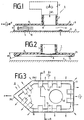
- FIG. 4 shows a section through the sole plate 6 from FIG. 3 along the bent section line AB.
- the section runs through the edge bead 11 including the edge bead portion 13 with the flattened inside.
- the cut at point B runs through a radial opening 14.
- the openings 14 can be comb-like incisions in the edge bead 11.
- the comb-like incisions can be formed when the edge bead 11 is sawn in from the underside of the sole plate 6.
- the number and size of the bores, slots and openings 14 make it possible to select the levitation height of the ironing device for a given air throughput of the blower 2.
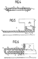
- FIG. 5 shows a further exemplary embodiment of the invention.
- the ironing device 1 according to FIG. 5 differs from the ironing device according to FIG. 1 in that the outlet opening 8 for the air flow is arranged at the edge 9 of the sole plate 6, the direction of flow of the air flow being directed under the sole plate 6.
- the textile material 3 is not shown in Fig. 5 for better clarity. Because the air flow WL is directed under the sole plate 6, there is a very large outflow path. A large part of the air flow WL therefore flows through the entire sole plate 6 in its longitudinal direction at a sufficient flow speed. Although the air flow WL is blown from the edge 9 of the sole plate 6 under the sole plate, the entire air flow WL contributes to the construction of the air cushion 10.
- the sole plate 6 can also have the edge bead 11 described above, including the openings 14.
- the blower 2 can be a permanently integrated blower in all exemplary embodiments, which generates warm air, for example.
- the blower 2 is a hair dryer, which is coupled to the tube 7 via a sealing quick coupling.
- the hairdryer can also be used as an ironing device with the aid of the sole plate 6, which is particularly advantageous when traveling.
- guide webs for the air flow WL are perpendicular to the underside of the sole plate 6 and are aligned so that the air flow WL must run along a preferred flow path.
- exemplary embodiments are conceivable in which, starting from the outlet opening 8, 6 guide channels run in the longitudinal direction of the soleplate on the underside.
- the walls of the guide channels are preferably not higher than the edge bead 11, if one is provided.
- the walls of the guide channels can have interruptions or not directly abut the edge bead 11.
- the walls of the flow channels prevent the air cushion 10 from flowing off to the side (y direction) too easily.
- the ironing device 1 which floats on the air cushion 10, has a substantially better stability. That is, the ironing device 1 does not automatically change its parking position when the fan 2 is running and the ironing device 1 does not drift as quickly. Likewise, the air cushion does not collapse so quickly when the sole plate 1 protrudes laterally over an edge.
- webs extending transversely to the direction of flow can also be provided on the underside of the soleplate 6, which contribute to the swirling.
- Fig. 6 shows a further embodiment in which the air flow WL is blown from all sides from the edge under the sole plate 6.
- the sole plate 6 is connected to an outer wall 19 on the upper side via retaining webs 17.
- the height of the holding webs 17 thus determine the height of a flow channel between rule the outer wall 19 and the top of the sole plate 6.
- the air flow WL is guided over the tube into the flow channel 18, in which the air flow WL impacts the top of the sole plates 6 and is distributed radially to the flow channel 18 on all sides.
- the deflected air flow WL emerges at the outlet opening 8 running around the edge.
- the air flow emerging from the outlet opening 8 is in turn directed under the sole plate 6.
- individual flow channels 18 can also run between the outer wall 19 and the sole plate 6 to outlet openings 8, which are arranged at suitable locations on the edge of the ironing device 1. It is also possible to provide bores 16 in the sole plate 6 through which a portion of the air flow WL can emerge perpendicularly from the sole plate 6.
- a movement switch or vibration switch which detects whether the ironing device is in operation or has been switched off. By means of the switch, the blower 2 is then automatically switched off after a certain period of time when not in use. If the ironing device 1 is gripped in order to continue ironing, the switch detects the movement and lifting of the ironing device 1 from the parking space and immediately switches on the fan. The ironing device 1 is thus switched on again in the period in which the ironing device is moved from the parking space onto the material to be ironed.
- the ironing device according to the invention is thus much more energy efficient than conventional irons. It is also possible to provide a magnet at the parking space which influences a switch in the ironing device when the ironing device 1 is placed on the parking space.
- the switch sensitive to magnetic field strength is preferably a reed contact which can be easily accommodated and cast in, for example, the soleplate 6.
- the parking space of the ironing device 1 is adapted to the basic shape of the sole plate 6 and in the area in which the reed contact comes to rest when the ironing device 1 is switched off, a magnet is arranged.
- the magnet is a glued-on magnetic film.
Abstract
Description
Die Erfindung betrifft eine Vorrichtung zum Bügeln eines auf einer Unterlage aufliegenden Textilmaterials, bei dem aus einer Sohlenplatte der Bügelvorrichtung ein von einem Gebläse erzeugter, über einen Strömungskanal zu wenigstens einer Austrittsöffnung in der Sohlenplatte geführter Luftstrom austritt.The invention relates to a device for ironing a textile material lying on a base, in which an airflow generated by a blower and led via a flow channel to at least one outlet opening in the soleplate emerges from a soleplate of the ironing device.
Aus der DE-OS-2 224 780 ist ein Bügeleisen bekannt, das einen Kompressor aufweist, der einen Luftstrom erzeugt. An der Unterseite der Bügelplatte sind am Bügelplattenrand Austrittsöffnungen für den Luftstrom vorgesehen. Der von dem Kompressor erzeugte Luftstrom strömt in dem Bügeleisen durch Strömungskanäle, in denen der Luftstrom erwärmt wird. Der aus den Austrittsöffnungen austretende Warmluftstrom wird durch das auf die Unterlage aufgelegte Textilmaterial umgelenkt, strömt nach allen Richtungen radial von dem Bügeleisen weg und dient zum Trocknen und Glätten des zu bügelnden Textilmaterials. Die Warmluft wird somit entlang dem Umriß des Bügeleisens verteilt. Da der Warmluftstrom unter hohem Druck aus den Austrittsöffnungen senkrecht auf das zu bügelnde Textilmaterial trifft, tritt gleichzeitig ein Entlastungseffekt durch Verminderung der Gleitreibung für das schwere Bügeleisen ein, ohne daß der unmittelbare Kontakt zwischen Bügelsohle und zu bügelndem Material abbricht.From DE-OS-2 224 780 an iron is known which has a compressor which generates an air flow. Outlet openings for the air flow are provided on the underside of the ironing plate at the edge of the ironing plate. The air flow generated by the compressor flows in the iron through flow channels in which the air flow is heated. The hot air stream emerging from the outlet openings is deflected by the textile material placed on the base, flows radially away from the iron in all directions and serves to dry and smooth the textile material to be ironed. The warm air is thus distributed along the outline of the iron. Since the hot air stream hits the textile material to be ironed vertically under high pressure from the outlet openings, a relief effect occurs at the same time by reducing the sliding friction for the heavy iron, without the direct contact between the soleplate and the material to be ironed breaking off.
Mit dem Entlastungseffekt des Bügeleisens - durch den lediglich aus den randseitigen Austrittsöffnungen senkrecht nach unten austretenden Luftstrom - wird der Kontakt der erhitzten Bügelplatte zu dem zu bügelnden Textilmaterial verschlechtert. D. h., der Vorteil, der durch die Trockenwirkung des Warmluftstroms unter Umständen erreicht wird, wird durch den verringerten Druck der Bügelplatte auf das Textilmaterial gemindert. Das Bügeleisen nach der DE-OS-2 224 780 benötigt daher wesentlich größere Energiemengen zum Bügeln als ein herkömmliches Bügeleisen.With the relief effect of the iron - due to the air stream only emerging vertically downwards from the edge-side outlet openings - the contact of the heated ironing plate with the textile material to be ironed is deteriorated. In other words, the advantage that the drying effect of the warm air flow may achieve is reduced by the reduced pressure of the ironing plate on the textile material. The iron according to DE-OS-2 224 780 therefore requires significantly larger amounts of energy for ironing than a conventional iron.
Ferner ist aus der JP-GM-4 821 008 ein auch als Bügeleisen verwendbarer Haartrockner mit Austrittsöffnungen in der Bügelplatte bekannt. Aus den Austrittsöffnungen strömt Warmluft, die dadurch erzeugt wird, daß über eine an der Gehäusevorderwand des Bügeleisens angebrachte Öffnung von einem einen Rotor aufweisenden Gebläse Luft angesaugt und über eine erste Heizeinrichtung den in der Bügelplatte enthaltenen Öffnungen zugeführt wird. Wird der Rotor im umgekehrten Drehsinn betrieben und befindet sich das Gerät nicht zum Zwecke des Bügelns in Kontakt mit einem Textilmaterial, so strömt über die an der Bügelplatte angebrachten Öffnungen Luft ein, die dann in einer zweiten Heizeinrichtung erwärmt wird und an der an der Vorderseite des Geräts angebrachten Öffnung austritt. Bei diesem Drehsinn des Rotors dient das Gerät als Haartrockner. Abgesehen davon, daß dieses Gerät aufgrund seiner zweier Heizeinrichtungen relativ kompliziert aufgebaut ist, bleibt es auch beim Bügeln in Kontakt mit dem zu bügelnden Textilmaterial, d. h, daß auch hier beim Bügeln vom Benutzer ein nennenswerter Kraftaufwand zu erbringen ist.Furthermore, JP-GM-4 821 008 discloses a hair dryer which can also be used as an iron and has outlet openings in the ironing plate. Warm air flows from the outlet openings, which air is generated in that air is sucked in by a fan having a rotor via an opening provided on the front wall of the iron of the iron and is fed to the openings contained in the ironing plate via a first heating device. If the rotor is operated in the opposite direction of rotation and the device is not in contact with a textile material for the purpose of ironing, air flows in via the openings in the ironing plate, which is then heated in a second heating device and at the front of the Device opening emerges. With this direction of rotation of the rotor, the device serves as a hair dryer. Apart from the fact that this device is relatively complicated due to its two heating devices, it also remains in contact with the textile material to be ironed when ironing. h that the user has to exert considerable effort when ironing.
Aus der US-PS-2 864 185 ist ein Bügeleisen bekannt, bei dem sich während des Bügelvorgangs zwischen der Oberfläche der Sohlenplatte und dem zu bügelnden Textilmaterial ein Luftpolster ausbildet. Um ein Schweben des Bügeleisens auf dem Textilmaterial zu erreichen, wird vorgeschlagen, Druckluft von einer Fremdenergiequelle über eine in der Sohlenplatte ausgebildete Öffnung auf das Textilmaterial auftreffen zu lassen. Damit sich zwischen der Oberfläche der Sohlenplatte und dem auf die Unterlage aufgelegten Textilmaterial tatsächlich ein großflächiges Luftpolster bildet, wird die Oberfläche zusätzlich noch leicht konkav ausgebildet. Um das Bügeleisen mit einem Gewicht von ungefähr 2 kp und mit einer Oberfläche der Sohlenplatte von etwa 200 cm2 zum Schweben zu bringen, ist Druckluft von 0,7 bar und ein Luftdurchsatz durch die Öffnung an der Sohlenplatte von ca. 300 1/min. erforderlich. Damit diese Werte erreicht werden können, ist ein Luftkompressor erforderlich, der aufwendig und teuer ist, so daß eine Bügelvorrichtung entsteht, die kaum im Haushaltsbereich, sondern vorwiegend nur im kommerziellen Bereich Anwendung finden kann.From US-PS-2 864 185 an iron is known, in which an air cushion forms during the ironing process between the surface of the soleplate and the textile material to be ironed. In order to allow the iron to float on the textile material, it is proposed to allow compressed air from an external energy source to strike the textile material via an opening formed in the soleplate. So that a large air cushion is actually formed between the surface of the soleplate and the textile material placed on the base, the surface is additionally made slightly concave. In order to levitate the iron with a weight of approximately 2 kg and with a surface of the sole plate of approximately 200 cm 2 , compressed air is 0.7 bar and an air throughput through the opening on the sole plate of approximately 300 1 / min. required. In order for these values to be achieved, an air compressor is required which is complex and expensive, so that an ironing device is produced which can hardly be used in the household sector, but predominantly only in the commercial sector.
Es war daher Aufgabe der Erfindung, eine Bügelvorrichtung anzugeben, die beim Bügeln unter der Sohlenplatte ein zum Schweben der Bügelvorrichtung ausreichendes Luftpolster ausbildet, ohne dazu Gebläse von im Haushaltsbereich unüblich großer Leistung zu verwenden oder gar den Anschluß der Bügelvorrichtung an eine Druckluftquelle vorzusehen. Darüber hinaus bestand die Aufgabe, die Bügelvorrichtung aus einfachen Teilen und preiswert zusammensetzbar auszubilden.It was therefore an object of the invention to provide an ironing device which, when ironing under the soleplate, forms an air cushion sufficient for the ironing device to float without using blowers of unusually high power in the household sector or even providing the ironing device to be connected to a compressed air source. In addition, the task was to design the ironing device from simple parts and inexpensive to assemble.
Die Lösung dieser Aufgabe erfolgte dadurch, daß das Gebläse in einem an die Sohlenplatte ankoppelbaren Haartrockner enthalten ist und daß an der Sohlenplatte ein auf das Textilmaterial gerichteter Randwulst ausgebildet ist.This object was achieved in that the blower is contained in a hair dryer which can be coupled to the soleplate and in that an edge bead directed onto the textile material is formed on the soleplate.
Bei der erfindungsgemäßen Bügelvorrichtung findet über die gesamte Sohlenplatte kein direkter Kontakt zu dem zu bügelnden Textilmaterial statt. Die Bügelwirkung beruht daher auf der Strömung des die Bügelvorrichtung tragenden Luftpolsters und kann daher ohne Kontaktwärme erfolgen. Der aus der Austrittsöffnung austretende Luftstrom dient somit zum Tragen der Bügelvorrichtung und zum Austreiben der Feuchtigkeit aus dem Textilmaterial. Ferner ist es nicht erforderlich, die Sohlenplatte besonders glatt zu bearbeiten, da die Gleitreibung zwischen Bügelsohle und Textilmaterial entfällt. Außerdem geht keine Brandgefahr von der Sohlenplatte aus.In the ironing device according to the invention, there is no direct contact with the textile material to be ironed over the entire sole plate. The ironing effect is therefore based on the flow of the air cushion carrying the ironing device and can therefore take place without contact heat. The air stream emerging from the outlet opening thus serves to carry the ironing device and to expel the moisture from the textile material. Furthermore, it is not necessary to process the sole plate particularly smoothly since the sliding friction between the soleplate and the textile material is eliminated. In addition, there is no risk of fire from the soleplate.
Obwohl die Bügelvorrichtung auf dem Luftpolster schwebt, überträgt sich die Gewichtskraft des Bügeleisens über das großflächige Luftpolster auf das zu bügelnde Textilmaterial. Die Glättwirkung durch das Gewicht der Bügelvorrichtung geht so nicht verloren, obwohl die nachteilige Reibung zwischen Sohlenplatte und Textilmaterial vermieden wird. Um ein möglichst großflächiges Luftpolster zu erreichen, wird der Luftstrom über lange Strömungswege unter der Sohlenplatte geführt. Ebenso wird der Druck des Luftstroms so gewählt, daß sich ein ausreichender statischer Druck zwischen der Sohlenplatte und dem Textilmaterial einstellt, der ausreicht, um die Bügelvorrichtung eine bestimmte Wegstrecke von dem Textilmaterial abzuheben.Although the ironing device hovers on the air cushion, the weight of the iron is transferred to the textile material to be ironed via the large air cushion. The smoothing effect of the weight of the ironing device is not lost, although the adverse friction between the sole plate and textile material is avoided. In order to achieve an air cushion that is as large as possible, the air flow is guided over long flow paths under the sole plate. Likewise, the pressure of the air flow is selected so that a sufficient static pressure is established between the sole plate and the textile material, which is sufficient to lift the ironing device a certain distance from the textile material.
Der Nachteil, der mit den aus dem Stand der Technik bekannten Bügeleisen verbunden ist, nämlich, daß große Luftanteile am Sohlenplattenrand schnell abfließen können, tritt beim Gegenstand der vorliegenden Erfindung nicht auf. Der Trageffekt des Bügeleisens durch den Luftstrom - der beim Stand der Technik gar nicht erwünscht ist und zum mangelnden Kontakt der erhitzten Bügelplatte mit dem Textilmaterial führt - wird bei der vorliegenden Erfindung mit wesentlich geringeren Gebläseleistungen erreicht. Die erfindungsgemäße Bügelvorrichtung weist dazu an der Sohlenplatte einen Randwulst auf. Mittels des Randwulstes entsteht ein abgegrenzter Stauraum für den Luftstrom unter der Sohlenplatte. Der Randwulst behindert das Abströmen des Luftstroms und trägt dazu bei, daß bei geringeren Gebläseleistungen der Luftkissen- bzw. Luftpolstereffekt erhöht wird.The disadvantage associated with the irons known from the prior art, namely that large amounts of air can flow off quickly at the edge of the soleplate, does not occur with the subject matter of the present invention. The supporting effect of the iron by the air flow - which is not at all desirable in the prior art and leads to insufficient contact of the heated ironing plate with the textile material - is achieved in the present invention with significantly lower blower outputs. For this purpose, the ironing device according to the invention has an edge bead on the soleplate. The edge bead creates a delimited storage space for the air flow under the sole plate. The edge bead hinders the outflow of the air flow and contributes to the fact that the air cushion or air cushion effect is increased at lower blower outputs.
Gemäß einer vorteilhaften Weiterbildung der Erfindung (Anspruch 2) wird ein Warmluftstrom verwendet, wodurch eine ähnliche Wirkung wie durch eine schwere, wärmespeichernde Sohlenplatte eines herkömmlichen Bügeleisens erzielt wird, obwohl es sich bei der Sohlenplatte nur um eine einfache, dünne Kunststoff- oder Metallplatte handeln kann, die mit dem auf die Unterlage aufgelegten Textilmaterial einen Abströmkanal für die Warmluft ausbildet. Daneben ist es möglich, einen wasserdampfhaltigen Luftstrom zu verwenden (Anspruch 3).According to an advantageous further development of the invention (claim 2), a warm air flow is used, whereby a similar effect is achieved as by a heavy, heat-storing soleplate of a conventional iron, although the soleplate can only be a simple, thin plastic or metal plate which forms an outflow channel for the warm air with the textile material placed on the base. In addition, it is possible to use a water vapor-containing air stream (claim 3).
Bei einer weiteren vorteilhaften Ausführungsform der Erfindung (Anspruch 4) ist die Austrittsöffnung für den Luftstrom im mittleren Bereich der Sohlenplatte angeordnet. Hierdurch ergeben sich große Strömungswege für den Luftstrom aus dem mittleren Bereich bis zum Rand der Sohlenplatte. Es kann so ein großflächiges Luftpolster über die gesamte Sohlenplatte ausgebildet werden. Jeder Anteil des Luftstromes wird deshalb gezwungen, eine bestimmte Wegstrecke aus dem mittleren Bereich der Sohlenplatte bis zum Sohlenplattenrand zu durchlaufen, wodurch der gesamte Luftstrom ausgenutzt wird, um ein trocknendes und tragfähiges Luftpolster auszubilden.In a further advantageous embodiment of the invention (claim 4), the outlet opening for the air flow is arranged in the central region of the sole plate. This results in large flow paths for the air flow from the central area to the edge of the soleplate. A large air cushion can be formed over the entire sole plate. Every part of the air flow is therefore forced to travel a certain distance from the central area of the sole plate to the edge of the sole plate, whereby the entire air flow is used to form a drying and stable air cushion.
Bei einer anderen Ausführungsform der Erfindung (Anspruch 5) ist die Austrittsöffnung für den Luftstrom am Sohlenplattenrand angeordnet und die Strömungsrichtung des Luftstroms unter die Sohlenplatte gerichtet. Der gesamte Luftstrom wird hier gleichfalls zum Tragen der Bügelvorrichtung ausgenutzt.In another embodiment of the invention (claim 5), the outlet opening for the air flow is arranged on the edge of the soleplate and the direction of flow of the airflow is directed under the soleplate. The entire air flow is also used here to carry the ironing device.
Weitere vorteilhafte Ausführungsformen der Erfindung lassen sich aus den Unteransprüchen 6 bis 14 entnehmen.Further advantageous embodiments of the invention can be found in
Nachfolgend wird die Erfindung anhand der Zeichnung näher beschrieben. Es zeigen:
- Fig. 1 ein erstes Ausführungsbeispiel einer Sohlenplatte nach der Erfindung;
- Fig. 2 eine Sohlenplatte aus Fig. 1 mit einem Randwulst;
- Fig. 3 eine Ansicht von unten auf eine Sohlenplatte mit Durchbrüchen in dem Randwulst;
- Fig. 4 einen Schnitt entlang der Schnittlinie AB der Sohlenplatte aus Fig. 3;
- Fig. 5 ein zweites Ausführungsbeispiel einer Sohlenplatte nach der Erfindung und
- Fig. 6 ein drittes Ausführungsbeispiel einer Sohlenplatte nach der Erfindung.
- Figure 1 shows a first embodiment of a sole plate according to the invention.
- FIG. 2 shows a sole plate from FIG. 1 with an edge bead;
- Figure 3 is a bottom view of a sole plate with openings in the bead.
- FIG. 4 shows a section along the section line AB of the sole plate from FIG. 3;
- Fig. 5 shows a second embodiment of a sole plate according to the invention and
- Fig. 6 shows a third embodiment of a sole plate according to the invention.
Fig. 1 zeigt ein erstes Ausführungsbeispiel einer Bügelvorrichtung 1 gemäß der vorliegenden Erfindung im Längsschnitt. Der Bügelvorrichtung 1 wird von einem Gebläse 2 ein Luftstrom WL zugeführt. Der Luftstrom WL wird über einen Tubus 7 zu einer Austrittsöffnung 8 in einer Sohlenplatte 6 geführt.Fig. 1 shows a first embodiment of an
Die Austrittsöffnung 8 ist im mittleren Bereich der Sohlenplatte 6 angeordnet. Die Sohlenplatte 6 ersteckt sich somit ausgehend von der Austrittsöffnung 8 bis zu einem Rand 9 der Sohlenplatte 6.The
Auf einer Unterlage 4 ist ein zu bügelndes Textilmaterial 3 aufgelegt, das wie in Fig. 1 gezeigt, Falten 5 aufweist. Wird das Gebläse 2 in Betrieb gesetzt, strömt der Luftstrom in den Tubus 7 und gelangt über die Austrittsöffnung 8 zwischen die Sohlenplatte 6 und das zu bügelnde Textilmaterial 3. Der Druck und die Luftmenge des von dem Gebläse 2 erzeugten Luftstroms WL ist so gewählt, daß der Luftstrom WL eine ausreichende Energie aufweist, um die Kräfte aufzubringen, die die Bügelvorrichtung 1 um einen bestimmten Betrag "h" von dem zu bügelnden Textilmaterial abheben. Der Luftstrom WL zwängt sich somit nach allen Richtungen zwischen die Sohlenplatte 6 und das Textilmaterial 3 und bildet so ein tragfähiges Luftpolster 10 für die Bügelvorrichtung 1. D. h., die Bügelvorrichtung 1 wird durch den ständig nachströmenden Luftstrom WL, der das Luftpolster 10 ausbildet, getragen. Weiter strömt der Luftstrom von der Austrittsöffnung 8 parallel zu dem Textilmaterial 3 über den Rand 9 der Sohlenplatte 6 hinausgehend ab.A textile material 3 to be ironed, which has folds 5 as shown in FIG. 1, is placed on a
In Fig. 1 ist das Luftpolster 10 in Form von Strömungslinien dargestellt, die Kräfte auf die Falten 5 des Textilmaterials 3 ausüben und die Falten 5 beseitigen. Ebenso nimmt das strömende Luftpolster 10 die in dem Textilmaterial 3 enthaltene Feuchtigkeit auf und transportiert die Feuchtigkeit aus einem großen Bereich, der sich über die Fläche der Sohlenplatte 6 hinaus erstreckt. Da die Austrittsöffnung 8 im mittleren Bereich der Sohlenplatte 6 angeordnet ist, ergeben sich große Abströmwege für den Luftstrom WL, weshalb das strömende Luftpolster 10 ausreichend Zeit hat, um die Feuchtigkeit in dem Textilmaterial 3 aufzunehmen bzw. mitzureißen. Das Gewicht der Bügelvorrichtung 1 überträgt sich über das Luftpolster 10 in gleicher Weise auf das zu bügelnde Textilmaterial 3, als wenn die Sohlenplatte 6 wie bei herkömmlichen Bügelverfahren direkt auf dem Textilmaterial 3 aufliegt. Die Glättwirkung der Bügelvorrichtung 1 wird so über die Sohlenplatte 6 und das vorgelagerte Luftpolster 10 erreicht, wodurch das Beseitigen von Falten 5 unterstützt wird. Ein wesentlicher Vorteil der auf dem Luftpolster 10 bzw. Luftkissen schwebenden Bügelvorrichtung 1 besteht darin, daß keinerlei Reibung zwischen der Sohlenplatte 6 und dem Textilmaterial 3 auftritt. Die Nachteile, daß bei bekannten Bügelverfahren infolge der Reibung und des hohen Anpreßdruckes das Textilmaterial abgewetzt wird oder Glanzstellen bekommt, besteht nach der Erfindung nicht mehr. Ebenso werden an die Unterseite der Sohlenplatte 6 keine hohen Gleitanforderungen gestellt, wie bei herkömmlichen Bügelplatten von Bügeleisen. Die Herstellung der Sohlenplatte 6 ist deshalb wesentlich einfacher und kostengünstiger als bei einem herkömmlichen Bügeleisen. Zudem läßt sich die Bügelvorrichtung 1 infolge der geringeren Reibung zwischen den Luftmolekülen des Luftpolsters 10 wesentlich leichter verschieben.In Fig. 1, the
Daneben ist es in energiesparender Weise nicht mehr erforderlich, die Sohlenplatte durch eine Heizung zu erwärmen, wobei sich keine längeren Bügelzeiten ergeben.In addition, it is no longer necessary in an energy-saving manner to heat the soleplate by means of a heater, with no longer ironing times.
Je nach Anwendungsfall ist der Luftstrom WL kalt oder erwärmt. Jedoch ist es vorteilhaft, wenn es sich bei dem Gebläse 2 um ein Warmluftgebläse handelt. Durch den Fortfall der Heizung in der Sohlenplatte 6 wird deren Herstellung zusätzlich vereinfacht. Gegebenenfalls kann der Luftstrom WL und besonders als Warmluftstrom einen Wasserdampfgehalt aufweisen, der in bekannter Weise zum Dämpfen dient. Ebenso kann Dampf, Wasser oder Feuchtigkeit nicht gezeigten Düsen in der Sohlenplatte 6 zugeführt werden. Ferner ist es möglich den Dampf je nach Bedarf in dem Gebläse 2 oder in dem Bereich des Tubusses 7 zu injizieren.Depending on the application, the air flow WL is cold or heated. However, it is advantageous if the
Die Austrittsöffnung 8 ist in einer Position in der Sohlenplatte 6 angeordnet, an der die durch das Luftpolster 10 auf die Sohlenplatte 6 ausgeübten Kräfte den Kippmomenten entgegenwirken, die bezogen auf die Austrittsöffnung 8 als Drehpunkt von der Bügelvorrichtung 1 ausgehen. D. h. das in Fig. 1 angedeutete Gebläse 2 kippt infolge der nach links ausgedehnten Gewichtsanteile die Bügelvorrichtung 1 im Gegenuhrzeigersinn. Um dies auszugleichen ist der vordere Abschnitt der Sohlenplatte 6 wesentlich länger als der hintere. Der vordere Abschnitt der Sohlenplattenfläche wirkt so als wesentlich längerer Hebel als der hintere Abschnitt. Die von dem Luftpolster 10 ausgehenden Kräfte, die an dem vorderen Abschnitt der Sohlenplatte 6 angreifen, heben das von dem Gebläse 2 bewirkte linksdrehende Kippmoment auf. Die Austrittsöffnung 8 liegt deshalb vorzugsweise auf der Längsachse (x-Achse) der Sohlenplatte 6. Ebenso ist die Austrittsöffnung 8 in Querrichtung der Sohlenplatte 6 in einer Position angeordnet, daß die Kippmomente um die Längsachse der Sohlenplatte 6 (x-Achse) ausgeglichen werden. Infolge der vorteilhaften Anordnung der Austrittsöffnung 8 in dem mittleren Bereich der Sohlenplatte 6, weist der Rand 9 der Sohlenplatte 6 im Schwebezustand im wesentlichen an allen Stellen die gleiche Höhe h auf.The
Beispielsweise besteht die Sohlenplatte 6 samt dem Tubus 7 aus Kunststoff, die in einem Stück gespritzt werden. Wenn die Sohlenplatte 6 keine Heizung aufweist, kann die Sohlenplatte sehr dünn - vorzugsweise 1 bis 3 mm - ausgelegt werden. Die Sohlenplatte 6 läßt sich deshalb sehr leicht und kostengünstiger herstellen als eine herkömmliche Bügelplatte eines Bügeleisens. Der Rand 9 der Sohlenplatte 6 ist abgerundet, damit der Rand 9 das Textilmaterial nicht beschädigen kann, wenn der Rand 9 beispielsweise an hochstehende Falten 5 anstößt.For example, the
Fig. 2 zeigt eine Bügelvorrichtung 1 mit einer Sohlenplatte 6, die einen vorzugsweise umlaufenden Randwulst 11 aufweist. Zur besseren Übersichtlichkeit wurde in Fig. 2 das Gebläse 2 und das Textilmaterial 3 nicht gezeichnet. Der Randwulst 11 weist ebenfalls äußere gerundete Kanten auf, um hochstehende Textilmaterialkanten nicht zu beschädigen oder besser darüberzugleiten. Die Innenseite 12 des Randwulst 11 ist bezogen auf die waagrecht ausgerichtete Sohlenplatte 6 um einen nach unten gerichteten Winkel a abgeflacht. Mittels des Randwulstes 11 wird ein Stauraum für das Luftpolster 10 ausgebildet, das im Vergleich zu Fig. 1 am Abströmen behindert wird. Zusätzlich erfährt das abströmende Luftpolster 10 an der Innenseite 12 des Randwulstes 11 eine Richtungsänderung um den Winkel a, wodurch das Abheben und Schweben der Bügelvorrichtung 1 infolge der Kräfte begünstigt wird, die aus der Umlenkung des Luftstromes resultieren. Der Staudruck bzw. der statische Druck wird deshalb in Vergleich zu dem Ausführungsbeispiel aus Fig. 1 bei gleicher Gebläseleistung durch den Randwulst 11 erhöht. In Fig. 2 ist die Kante an der Austrittsöffnung 8 zum besseren und leichteren Umlenken des Luftstroms WL abgerundet. Ebenfalls ist die Verbindungsstelle, an der der Tubus 7 auf der Sohlenplatte 6 aufsitzt, verstärkt. Obwohl die Sohlenplatte 6 in den soweit beschriebenen Ausführungsbeispielen und in den noch zu beschreibenden Ausführungsbeispielen in weiten Bereichen parallel zur Unterlage verläuft, ist es auch möglich, die Sohlenplatte 6 gekrümmt aufzubauen. Die Sohlenplatte 6 kann in diesem Fall beispielsweise konkav gekrümmt sein.2 shows an
Fig. 3 zeigt die Bügeleinrichtung 1 aus Fig. 2 in der Ansicht von unten. Die Sohlenplatte 6 weist an der Vorderseite in bekannter Weise eine Spitze auf. Der restliche Teil der Sohlenplatte ist in dem in Fig. 3 gezeigten Ausführungsbeispiel rechteckförmig ausgebildet. Abweichend von Fig. 3 kann die Sohlenplatte 6 je nach Anwendungsfall eine andere geeignete Grundform aufweisen. Wie der Fig. 3 weiter zu entnehmen ist, liegt die Austrittsöffnung 8 - wie zuvor beschrieben - auf der Längsachse der Sohlenplatte 6 (x-Achse). Die Lage der Austrittsöffnung 8 auf der Längsachse ergibt sich durch die zuvor beschriebene Gewichtsverteilung und den daraus resultierenden Kippmomenten um die in Fig. 3 gezeigte y-Achse. Die Größe der Austrittsöffnung 8 ist an die Luftdurchtrittsleistung des Gebläses 2 angepaßt. Zusätzlich und abweichend zu Fig. 2 weist der Randwulst in Fig. 3 Durchbrüche 14 auf. Mittels der Durchbrüche 14 kann der Luftaustritt an dem Randwulst 11 auf den Luftdurchsatz des Gebläses 2 abgestimmt werden. Ebenso dienen die Durchbrüche 14 zum Glattblasen von größeren Falten 5, die vor der Bügelvorrichtung 1 liegen. Weiter sind die radialen Durchbrüche 14 symmetrisch zur Längsachse der Sohlenplatte 6 angeordnet, wobei vorzugsweise an der Spitze der Sohlenplatte 6 ein Durchbruch 14 ausgebildet ist. Der an der Spitze der Sohlenplatte 6 ausgebildete Durchbruch 14 dient ebenso zum Glattdrücken von größeren Falten 5, auf die die Bügelvorrichtung 1 zubewegt wird. Durch das Ausbilden der Durchbrüche 14 im Randwulst 11 entstehen Aussparungen zwischen Randwulstabschnitten 13. Die Randwulstabschnitte 13 sind ebenfalls abgeflacht wie die Innenseite 12 der Randwulst 11 aus Fig. 2.FIG. 3 shows the
Fig. 4 zeigt einen Schnitt durch die Sohlenplatte 6 aus Fig. 3 entlang der abgeknickten Schnittlinie AB. Ausgehend von dem Punkt A verläuft der Schnitt durch den Randwulst 11 einschließlich dem Randwulstabschnitt 13 mit der abgeflachten Innenseite. Andererseits verläuft der Schnitt an dem Punkt B durch einen radialen Durchbruch 14. In der Mitte der Sohlenplatte 6 ist der an der Spitze liegende größere Durchbruch 14 zu erkennen. Gegebenenfalls kann es sich bei den Durchbrüchen 14 um kammartige Einschnitte in den Randwulst 11 handeln. Beispielsweise sind die kammartigen Einschnitte ausbildbar, wenn der Randwulst 11 von der Unterseite der Sohlenplatte 6 her eingesägt wird. Weiter ist es möglich in ähnlicher Weise Bohrungen in der Sohlenplatte 6 vorzusehen, aus denen das Luftpolster 10 teilweise nach oben austreten kann. Durch die Anzahl und Größe der Bohrungen, Schlitze und Durchbrüche 14 ist es möglich, die Schwebehöhe der Bügelvorrichtung bei einer vorgegebenen Luftdurchtrittsleistung des Gebläses 2 auszuwählen.FIG. 4 shows a section through the
Fig. 5 zeigt ein weiteres Ausführungsbeispiel der Erfindung. Die Bügelvorrichtung 1 nach Fig. 5 unterscheidet sich von der Bügelvorrichtung nach Fig. 1 darin, daß die Austrittsöffnung 8 für den Luftstrom am Rand 9 der Sohlenplatte 6 angeordnet ist, wobei die Strömungrichtung des Luftstroms unter die Sohlenplatte 6 gerichtet ist. Das Textilmaterial 3 ist in Fig. 5 zur besseren Übersichtlichkeit nicht dargestellt. Dadurch, daß der Luftstrom WL unter die Sohlenplatte 6 gerichtet ist, ergibt sich ein sehr großer Abströmweg. Ein Großteil des Luftstroms WL durchströmt deshalb bei einer ausreichenden Strömungsgeschwindigkeit die gesamte Sohlenplatte 6 in ihrer Längsrichtung. Obwohl der Luftstrom WL vom Rand 9 der Sohlenplatte 6 unter die Sohlenplatte geblasen wird, trägt der gesamte Luftstrom WL zum Aufbau des Luftpolsters 10 bei. Ein Abströmen des Luftstromes WL von dem Rand 9 ohne Durchlaufen eines größeren Strömungsweges unter der Sohlenplatte 6, wird durch das Ausrichten des Abströmwinkels nach innen verhindert. Die Sohlenplatte 6 kann gleichfalls den zuvor beschriebenen Randwulst 11 einschließlich der Durchbrüche 14 aufweisen. Je nach Anwendungsfall kann das Gebläse 2 in allen Ausführungsbeispielen ein fest integriertes Gebläse sein, das beispielsweise Warmluft erzeugt. Andererseits ergeben sich zahlreiche Vorteile und Anwendungsmöglichkeiten, wenn das Gebläse 2 ein Haartrockner ist, der über eine dichtende Schnellkupplung an dem Tubus 7 angekuppelt wird. Hierdurch läßt sich der Haartrockner unter Zuhilfenahme der Sohlenplatte 6 zusätzlich als Bügelvorrichtung verwenden, was besonders auf Reisen von Vorteil ist. Ferner ist es möglich in allen Ausführungsbeispielen an der Unterseite der Sohlenplatte 6 Führungsstege für den Luftstrom WL auszubilden. Die nicht gezeigten Führungsstege stehen dabei senkrecht auf der Unterseite der Sohlenplatte 6 und sind so ausgerichtet, daß der Luftstrom WL entlang eines bevorzugten Strömungsweges verlaufen muß. Beispielsweise sind Ausführungsbeispiele denkbar, in denen ausgehend von der Austrittsöffnung 8 in Längsrichtung der Sohlenplatte 6 Führungskanäle an der Unterseite verlaufen. Hierbei sind die Wände der Führungskanäle vorzugsweise nicht höher als der Randwulst 11, wenn ein solcher vorgesehen ist. Zur besseren Verteilung des Luftpolsters unter der Sohlenplatte 6 können die Wände der Führungskanäle Unterbrechungen aufweisen oder nicht direkt an den Randwulst 11 anstoßen. Durch die Wände der Strömungskanäle wird verhindert, daß das Luftpolster 10 zu leicht seitlich (y-Richtung) abströmen kann. Weiter erhält die Bügelvorrichtung 1, die auf dem Luftpolster 10 schwimmt, eine wesentlich bessere Standfestigkeit. D. h., die Bügelvorrichtung 1 verändert ihre Abstellposition bei laufendem Gebläse 2 nicht selbsttätig und die Bügelvorrichtung 1 treibt nicht so schnell ab. Ebenso bricht das Luftpolster nicht so schnell zusammen, wenn die Sohlenplatte 1 seitlich über eine Kante ragt. Je nach Anwendungsfall können auch quer zur Stromungsrichtung verlaufende Stege an der Unterseite der Sohlenplatte 6 vorgesehen sein, die zur Verwirbelung beitragen.5 shows a further exemplary embodiment of the invention. The
Fig. 6 zeigt ein weiteres Ausführungsbeispiel, bei dem der Luftstrom WL von allen Seiten vom Rand her unter die Sohlenplatte 6 geblasen wird. Hierzu ist die Sohlenplatte 6 an der Oberseite über Haltestege 17 mit einer Außenwandung 19 verbunden. Die Höhe der Haltestege 17 bestimmen so die Höhe eines Strömungskanals zwischen der Außenwandung 19 und der Oberseite der Sohlenplatte 6. Der Luftstrom WL wird über den Tubus in den Strömungskanal 18 geführt, in dem der Luftstrom WL auf die Oberseite der Sohlenplatten 6 prallt und radial nach allen Seiten in den Strömungskanal 18 verteilt wird. Nach dem Durchlaufen des Strömungskanals 18 tritt der umgelenkte Luftstrom WL an der am Rand umlaufenden Austrittsöffnung 8 aus. Der aus der Austrittsöffnung 8 austretende Luftstrom ist wiederum unter die Sohlenplatte 6 gerichtet. Gegebenenfalls können auch einzelne Strömungskanäle 18 zwischen der Außenwandung 19 und der Sohlenplatte 6 zu Austrittsöffnungen 8 verlaufen, die an geeigneten Stellen am Rand der Bügelvorrichtung 1 angeordnet sind. Ebenso ist es möglich, Bohrungen 16 in der Sohlenplatte 6 vorzusehen, über die ein Anteil des Luftstroms WL senkrecht aus der Sohlenplatte 6 treten kann.Fig. 6 shows a further embodiment in which the air flow WL is blown from all sides from the edge under the
Ferner ist es möglich einen Bewegungsschalter oder Erschütterungsschalter vorzusehen, der detektiert, ob die Bügelvorrichtung in Betrieb ist oder abgestellt wurde. Mittels des Schalters wird dann das Gebläse 2 bei Nichtbenutzung nach einer bestimmten Zeitdauer automatisch abgeschaltet. Wird die Bügelvorrichtung 1 ergriffen, um weiter zu Bügeln, detektiert der Schalter die Bewegung und das Abheben der Bügelvorrichtung 1 von dem Abstellplatz und schaltet sofort das Gebläse ein. Die Bügelvorrichtung 1 wird so in der Zeitspanne, in der die Bügelvorrichtung von dem Abstellplatz auf das zu bügelnde Material bewegt wird, wieder eingeschaltet. Die Bügelvorrichtung nach der Erfindung ist somit wesentlich energiesparender als herkömmliche Bügeleisen. Ebenso ist es möglich, an dem Abstellplatz einen Magnet vorzusehen, der einen Schalter in der Bügelvorrichtung beeinflußt wenn die Bügelvorrichtung 1 auf den Abstellplatz abgestellt wird. Vorzugsweise handelt es sich bei dem magnetfeldstärkeempfindlichen Schalter um einen Reedkontakt, der beispielsweise in der Sohlenplatte 6 leicht untergebracht und eingegossen werden kann. Der Abstellplatz der Bügelvorrichtung 1 ist hierzu an die Grundform der Sohlenplatte 6 angepaßt und in dem Bereich, in dem der Reedkontakt beim Abstellen der Bügelvorrichtung 1 zum Aufliegen kommt, ist ein Magnet angeordnet. Beispielsweise handelt es sich bei dem Magneten um eine aufgeklebte Magnetfolie.It is also possible to provide a movement switch or vibration switch which detects whether the ironing device is in operation or has been switched off. By means of the switch, the
Claims (14)
characterized in that the blower (2) is contained in a hair dryer adapted to be coupled to the soleplate (6), and that a beaded edge (11) directed against the fabric (3) is formed on the soleplate (6).
characterized in that the air stream (WL) is heated by a heating means arranged in the hair dryer (2).
characterized in that humidity is supplied to the heated air stream (WL).
characterized in that the discharge port (8) for the air stream (WL) is arranged in the center area of the soleplate (6).
characterized in that the discharge port (8) for the air stream (WL) is provided at the edge (9) of the soleplate (6), and that the air stream from the discharge port (8) is directed under the soleplate (6).
characterized in that the discharce port (8) lies on the longitudinal axis X of the soleplate (6).
characterized in that the beaded edge (11) has its inside (12) beveled.
characterized in that the beaded edge (11) includes radial vents (14).
characterized in that the vents (14) are arranged symmetrically to the longitudinal axis X of the soleplate (6).
characterized in that the hair dryer (2) is adapted to be coupled to the soleplate (6) by means of a tight quick-connect coupling.
characterized in that the soleplate (6) is made of a light-weight material, preferably a plastics material.
characterized in that the soleplate (6) has preferably a thickness of between 1 and 3 mm.
Priority Applications (1)
| Application Number | Priority Date | Filing Date | Title |
|---|---|---|---|
| AT86106374T ATE46930T1 (en) | 1985-05-22 | 1986-05-09 | IRONING DEVICE. |
Applications Claiming Priority (2)
| Application Number | Priority Date | Filing Date | Title |
|---|---|---|---|
| DE19853518425 DE3518425A1 (en) | 1985-05-22 | 1985-05-22 | METHOD FOR IRONING AND DEVICE FOR CARRYING OUT THE METHOD |
| DE3518425 | 1985-05-22 |
Publications (3)
| Publication Number | Publication Date |
|---|---|
| EP0202561A2 EP0202561A2 (en) | 1986-11-26 |
| EP0202561A3 EP0202561A3 (en) | 1987-08-05 |
| EP0202561B1 true EP0202561B1 (en) | 1989-10-04 |
Family
ID=6271372
Family Applications (1)
| Application Number | Title | Priority Date | Filing Date |
|---|---|---|---|
| EP86106374A Expired EP0202561B1 (en) | 1985-05-22 | 1986-05-09 | Ironing apparatus |
Country Status (8)
| Country | Link |
|---|---|
| US (1) | US4685229A (en) |
| EP (1) | EP0202561B1 (en) |
| JP (1) | JPS61272100A (en) |
| AT (1) | ATE46930T1 (en) |
| BR (1) | BR8602269A (en) |
| CA (1) | CA1268411A (en) |
| DE (2) | DE3518425A1 (en) |
| ES (1) | ES8703552A1 (en) |
Families Citing this family (13)
| Publication number | Priority date | Publication date | Assignee | Title |
|---|---|---|---|---|
| US4857706A (en) * | 1988-02-29 | 1989-08-15 | Diamond Paul J | Ironing accessory |
| US5170038A (en) * | 1991-07-23 | 1992-12-08 | Midori Co., Ltd. | Iron unit adapted to be used with hair dryers |
| US5333401A (en) * | 1993-02-01 | 1994-08-02 | Roberts Consolidated Industries, Inc. | Carpet seaming iron with air gap between cooling plates |
| US5787614A (en) * | 1993-03-30 | 1998-08-04 | Rowenta-Werke Gmbh | Electric steam iron with aerosol sprayer |
| DE19634870C1 (en) * | 1996-08-29 | 1997-10-16 | Rowenta Werke Gmbh | Steam iron has sole plate with central depression containing slightly-rounded elevations |
| DE20119767U1 (en) * | 2001-12-06 | 2002-02-21 | Chen Shou Mao | Multipurpose hairdryer |
| US6750747B2 (en) | 2002-08-29 | 2004-06-15 | Ljm Associates, Inc. | Proximity safety switch suitable for use in a hair dryer for disabling operation |
| US6784775B2 (en) * | 2002-08-29 | 2004-08-31 | Ljm Associates, Inc. | Proximity safety switch suitable for use in a hair dryer for disabling operation |
| FR2952385B1 (en) * | 2009-11-12 | 2012-01-20 | Seb Sa | IRON CONTAINING AN INSOLE HAVING AN EVIDENCE WITH VAPOR EXIT HOLES |
| FR2952386B1 (en) * | 2009-11-12 | 2011-10-28 | Seb Sa | IRON CONTAINING AN INSOLE HAVING AN EVIDENCE WITH VAPOR EXIT HOLES |
| US10883222B2 (en) * | 2017-09-12 | 2021-01-05 | Vivian Lou Lewis | Attachment to convert a standard handheld hair blow dryer into a device that can be used to iron clothing |
| DE202018104388U1 (en) | 2018-07-30 | 2018-09-03 | Brice Dupoyet | Irons for domestic or commercial use |
| FR3089525B1 (en) | 2018-12-06 | 2020-12-25 | Guy Dupoyet | IRON FOR DOMESTIC OR PROFESSIONAL USE |
Citations (1)
| Publication number | Priority date | Publication date | Assignee | Title |
|---|---|---|---|---|
| US2864185A (en) * | 1955-05-03 | 1958-12-16 | Hoover Co | Air floated iron |
Family Cites Families (10)
| Publication number | Priority date | Publication date | Assignee | Title |
|---|---|---|---|---|
| DE476394C (en) * | 1928-05-19 | 1929-05-16 | Joseph Schneider | Iron with an evaporation room and an air heater room |
| ES402122A1 (en) * | 1971-06-26 | 1975-03-01 | Azzolini | Improvements in electric plates that supply vapor and air to the fabric to iron. (Machine-translation by Google Translate, not legally binding) |
| US3870309A (en) * | 1973-11-20 | 1975-03-11 | Joseph Donatien Leo Tessier | Sliding game piece having friction reduction air cushion |
| US3992009A (en) * | 1975-02-03 | 1976-11-16 | Trbovich Nicholas D | Air cushion game |
| US4233763A (en) * | 1978-08-21 | 1980-11-18 | Nesco Products, Inc. | Steam iron with low temperature soleplate |
| JPS58500550A (en) * | 1981-04-18 | 1983-04-14 | ブラウン アクチエンゲゼルシヤフト | Electric irons, especially travel irons |
| DE3115696C2 (en) * | 1981-04-18 | 1983-05-19 | Braun Ag, 6000 Frankfurt | Electric iron |
| DE3202978C2 (en) * | 1982-01-29 | 1990-01-04 | Braun Ag, 6000 Frankfurt | Electric iron |
| DD219228A1 (en) * | 1983-11-11 | 1985-02-27 | Elektrogeraete Ingbuero Veb | ELECTRIC BUCKETS |
| DD221487A1 (en) * | 1984-02-16 | 1985-04-24 | Werkzeugmasch Heckert Veb | ELECTRIC MULTIPURPOSE UNIT, ESPECIALLY FOR USE AS TRAVEL TIPS AND HAND AIR SHOWER |
-
1985
- 1985-05-22 DE DE19853518425 patent/DE3518425A1/en active Granted
-
1986
- 1986-04-08 ES ES553766A patent/ES8703552A1/en not_active Expired
- 1986-05-09 EP EP86106374A patent/EP0202561B1/en not_active Expired
- 1986-05-09 DE DE8686106374T patent/DE3666057D1/en not_active Expired
- 1986-05-09 AT AT86106374T patent/ATE46930T1/en not_active IP Right Cessation
- 1986-05-20 US US06/865,380 patent/US4685229A/en not_active Expired - Fee Related
- 1986-05-20 BR BR8602269A patent/BR8602269A/en unknown
- 1986-05-20 CA CA000509510A patent/CA1268411A/en not_active Expired - Fee Related
- 1986-05-22 JP JP61116306A patent/JPS61272100A/en active Pending
Patent Citations (1)
| Publication number | Priority date | Publication date | Assignee | Title |
|---|---|---|---|---|
| US2864185A (en) * | 1955-05-03 | 1958-12-16 | Hoover Co | Air floated iron |
Also Published As
| Publication number | Publication date |
|---|---|
| US4685229A (en) | 1987-08-11 |
| CA1268411A (en) | 1990-05-01 |
| ES8703552A1 (en) | 1987-02-16 |
| BR8602269A (en) | 1987-01-21 |
| ATE46930T1 (en) | 1989-10-15 |
| EP0202561A2 (en) | 1986-11-26 |
| DE3518425C2 (en) | 1988-03-10 |
| DE3518425A1 (en) | 1986-11-27 |
| JPS61272100A (en) | 1986-12-02 |
| ES553766A0 (en) | 1987-02-16 |
| EP0202561A3 (en) | 1987-08-05 |
| DE3666057D1 (en) | 1989-11-09 |
Similar Documents
| Publication | Publication Date | Title |
|---|---|---|
| EP0202561B1 (en) | Ironing apparatus | |
| AT392991B (en) | DRYING PART FOR A MACHINE FOR THE PRODUCTION OR PROCESSING OF FIBER STRIPS, ESPECIALLY PAPER STRIPS | |
| DE3890457C2 (en) | Web drying method | |
| DE3910898A1 (en) | METHOD AND DEVICE IN A COMBINATION DRYER CONSISTING OF A GAS INFRARED ARRANGEMENT AND A SWIRL ARRANGEMENT | |
| EP0908551B1 (en) | Steam iron with steam output at the front and sides of the iron sole | |
| DE2836103C2 (en) | Air nozzle for a nozzle dryer | |
| EP0778131B1 (en) | Sheet guiding system for a printing machine | |
| EP0298299B1 (en) | Device for the contactless guiding of webs | |
| DE4029487A1 (en) | Coated paper drying - using blown air to form air cushion to carry web through dryers without contact | |
| DE10063672A1 (en) | Device for smoothing shirts with a divided inflatable body | |
| DE2351280B2 (en) | Impact jet dryer for web-shaped goods | |
| EP0723522B1 (en) | Device for the suspension guidance of a travelling web | |
| DE1460660A1 (en) | Device for drying textile fabric webs | |
| DE69815120T2 (en) | PAPER OR PAPER MACHINE WITH A SUCTION BOX | |
| EP0658427B1 (en) | Curing apparatus | |
| DE3209365C2 (en) | Process for operating a hot bowl ironer and hot bowl ironer therefor | |
| DE604269C (en) | Method and device for drying fabrics | |
| DE3822624C2 (en) | ||
| DE3115696C2 (en) | Electric iron | |
| DE2240713C3 (en) | Nozzle dryer for coated or printed webs | |
| DE1965719U (en) | DEVICE FOR SMOOTHING FLAT PIECES OF Linen. | |
| DE652238C (en) | Device for drying paper webs | |
| DE1034128B (en) | Drying machine for drying web-shaped material, in particular fabric tensioning and drying machine | |
| EP0501400A1 (en) | Drying device for laundry, in particulier for clothes | |
| DE1095246B (en) | Device for the continuous treatment, in particular drying, of web-like goods |
Legal Events
| Date | Code | Title | Description |
|---|---|---|---|
| PUAI | Public reference made under article 153(3) epc to a published international application that has entered the european phase |
Free format text: ORIGINAL CODE: 0009012 |
|
| AK | Designated contracting states |
Kind code of ref document: A2 Designated state(s): AT CH DE FR GB IT LI NL SE |
|
| PUAL | Search report despatched |
Free format text: ORIGINAL CODE: 0009013 |
|
| AK | Designated contracting states |
Kind code of ref document: A3 Designated state(s): AT CH DE FR GB IT LI NL SE |
|
| 17P | Request for examination filed |
Effective date: 19870820 |
|
| 17Q | First examination report despatched |
Effective date: 19881018 |
|
| ITF | It: translation for a ep patent filed |
Owner name: DE DOMINICIS & MAYER S.R.L. |
|
| GRAA | (expected) grant |
Free format text: ORIGINAL CODE: 0009210 |
|
| AK | Designated contracting states |
Kind code of ref document: B1 Designated state(s): AT CH DE FR GB IT LI NL SE |
|
| REF | Corresponds to: |
Ref document number: 46930 Country of ref document: AT Date of ref document: 19891015 Kind code of ref document: T |
|
| GBT | Gb: translation of ep patent filed (gb section 77(6)(a)/1977) | ||
| REF | Corresponds to: |
Ref document number: 3666057 Country of ref document: DE Date of ref document: 19891109 |
|
| ET | Fr: translation filed | ||
| PLBE | No opposition filed within time limit |
Free format text: ORIGINAL CODE: 0009261 |
|
| STAA | Information on the status of an ep patent application or granted ep patent |
Free format text: STATUS: NO OPPOSITION FILED WITHIN TIME LIMIT |
|
| 26N | No opposition filed | ||
| ITTA | It: last paid annual fee | ||
| PGFP | Annual fee paid to national office [announced via postgrant information from national office to epo] |
Ref country code: GB Payment date: 19920423 Year of fee payment: 7 |
|
| PGFP | Annual fee paid to national office [announced via postgrant information from national office to epo] |
Ref country code: FR Payment date: 19920428 Year of fee payment: 7 |
|
| PGFP | Annual fee paid to national office [announced via postgrant information from national office to epo] |
Ref country code: AT Payment date: 19920430 Year of fee payment: 7 |
|
| PGFP | Annual fee paid to national office [announced via postgrant information from national office to epo] |
Ref country code: DE Payment date: 19920505 Year of fee payment: 7 |
|
| PGFP | Annual fee paid to national office [announced via postgrant information from national office to epo] |
Ref country code: SE Payment date: 19920507 Year of fee payment: 7 |
|
| PGFP | Annual fee paid to national office [announced via postgrant information from national office to epo] |
Ref country code: NL Payment date: 19920531 Year of fee payment: 7 |
|
| PGFP | Annual fee paid to national office [announced via postgrant information from national office to epo] |
Ref country code: CH Payment date: 19920619 Year of fee payment: 7 |
|
| PG25 | Lapsed in a contracting state [announced via postgrant information from national office to epo] |
Ref country code: GB Effective date: 19930509 Ref country code: AT Effective date: 19930509 |
|
| PG25 | Lapsed in a contracting state [announced via postgrant information from national office to epo] |
Ref country code: SE Effective date: 19930510 |
|
| PG25 | Lapsed in a contracting state [announced via postgrant information from national office to epo] |
Ref country code: LI Effective date: 19930531 Ref country code: CH Effective date: 19930531 |
|
| PG25 | Lapsed in a contracting state [announced via postgrant information from national office to epo] |
Ref country code: NL Effective date: 19931201 |
|
| GBPC | Gb: european patent ceased through non-payment of renewal fee |
Effective date: 19930509 |
|
| NLV4 | Nl: lapsed or anulled due to non-payment of the annual fee | ||
| PG25 | Lapsed in a contracting state [announced via postgrant information from national office to epo] |
Ref country code: FR Effective date: 19940131 |
|
| REG | Reference to a national code |
Ref country code: CH Ref legal event code: PL |
|
| PG25 | Lapsed in a contracting state [announced via postgrant information from national office to epo] |
Ref country code: DE Effective date: 19940201 |
|
| REG | Reference to a national code |
Ref country code: FR Ref legal event code: ST |
|
| EUG | Se: european patent has lapsed |
Ref document number: 86106374.1 Effective date: 19931210 |
|
| PG25 | Lapsed in a contracting state [announced via postgrant information from national office to epo] |
Ref country code: IT Free format text: LAPSE BECAUSE OF NON-PAYMENT OF DUE FEES Effective date: 20050509 |