EP0202452A2 - Système de fixation et de repérage pour une machine d'électroérosion à fil - Google Patents
Système de fixation et de repérage pour une machine d'électroérosion à fil Download PDFInfo
- Publication number
- EP0202452A2 EP0202452A2 EP86104898A EP86104898A EP0202452A2 EP 0202452 A2 EP0202452 A2 EP 0202452A2 EP 86104898 A EP86104898 A EP 86104898A EP 86104898 A EP86104898 A EP 86104898A EP 0202452 A2 EP0202452 A2 EP 0202452A2
- Authority
- EP
- European Patent Office
- Prior art keywords
- reference part
- basic
- machine
- part according
- workpiece
- Prior art date
- Legal status (The legal status is an assumption and is not a legal conclusion. Google has not performed a legal analysis and makes no representation as to the accuracy of the status listed.)
- Granted
Links
- 238000005520 cutting process Methods 0.000 claims abstract description 15
- 238000009760 electrical discharge machining Methods 0.000 claims description 20
- 238000003754 machining Methods 0.000 description 24
- 238000004519 manufacturing process Methods 0.000 description 4
- 238000000034 method Methods 0.000 description 4
- 238000012545 processing Methods 0.000 description 4
- 238000010276 construction Methods 0.000 description 2
- 238000005516 engineering process Methods 0.000 description 2
- 238000003672 processing method Methods 0.000 description 2
- 230000000284 resting effect Effects 0.000 description 2
- 241000397426 Centroberyx lineatus Species 0.000 description 1
- 229910001315 Tool steel Inorganic materials 0.000 description 1
- 239000004020 conductor Substances 0.000 description 1
- 230000001419 dependent effect Effects 0.000 description 1
- 238000000227 grinding Methods 0.000 description 1
- 230000003993 interaction Effects 0.000 description 1
- 239000002184 metal Substances 0.000 description 1
- 238000003801 milling Methods 0.000 description 1
- 230000000149 penetrating effect Effects 0.000 description 1
- 238000012805 post-processing Methods 0.000 description 1
- 230000000630 rising effect Effects 0.000 description 1
- 238000007514 turning Methods 0.000 description 1
Images



Classifications
-
- B—PERFORMING OPERATIONS; TRANSPORTING
- B23—MACHINE TOOLS; METAL-WORKING NOT OTHERWISE PROVIDED FOR
- B23Q—DETAILS, COMPONENTS, OR ACCESSORIES FOR MACHINE TOOLS, e.g. ARRANGEMENTS FOR COPYING OR CONTROLLING; MACHINE TOOLS IN GENERAL CHARACTERISED BY THE CONSTRUCTION OF PARTICULAR DETAILS OR COMPONENTS; COMBINATIONS OR ASSOCIATIONS OF METAL-WORKING MACHINES, NOT DIRECTED TO A PARTICULAR RESULT
- B23Q16/00—Equipment for precise positioning of tool or work into particular locations not otherwise provided for
- B23Q16/001—Stops, cams, or holders therefor
-
- B—PERFORMING OPERATIONS; TRANSPORTING
- B23—MACHINE TOOLS; METAL-WORKING NOT OTHERWISE PROVIDED FOR
- B23H—WORKING OF METAL BY THE ACTION OF A HIGH CONCENTRATION OF ELECTRIC CURRENT ON A WORKPIECE USING AN ELECTRODE WHICH TAKES THE PLACE OF A TOOL; SUCH WORKING COMBINED WITH OTHER FORMS OF WORKING OF METAL
- B23H7/00—Processes or apparatus applicable to both electrical discharge machining and electrochemical machining
- B23H7/26—Apparatus for moving or positioning electrode relatively to workpiece; Mounting of electrode
Definitions
- the invention relates to a reference part for the exact positioning of a workpiece in a predetermined target position within the working area of a wire spark erosion machine relative to the cutting wire of the machine, on the clamping table of which outside the working area, at least one plane, in an x-direction and a perpendicular y-direction extending basic reference surface at the level of the lower limit (zero line) of the work area is formed in a z direction perpendicular to the x and y directions.
- Wire EDM machines have a mostly upper wire feed device and a usually lower wire discharge device, between which the cutting wire usually extends through the work area in the z direction.
- a basic reference surface is provided on the clamping table in the wire spark erosion machines that are considered for the invention, which is a reference in the z-direction for the positioning of the workpiece.
- the basic reference surface is usually the flat ground surface of a support rising from the clamping table in the z direction, which extends parallel to a lateral boundary of the working area. The beam rises above the worktop so that the basic reference surface is in the zero line of the work area, which is its lower limit in the z-direction, which is closest to the clamping table.
- wire EDM machines in which a beam with a basic reference surface extends along the opposite lateral boundaries of the working area, and there are other wire EDM machines in which the beam is designed as an angle, so that the basic reference surface is in the zero line extends along two adjacent lateral boundaries of the work area.
- the EDM machining of a workpiece using a cutting wire enables shapes to be produced from workpieces with extremely high accuracy and surface quality. Since wire EDM machining of a workpiece requires relatively long machining times, it is particularly important to keep the downtimes of a wire EDM machine caused by retooling and setting up a workpiece to be machined as short as possible.
- Devices are provided for spark erosion machines with reference surfaces, which allow a workpiece to be machined to be set up outside the machine on holders provided with counter-reference surfaces.
- the rapid naturalization as an accepted processing method can be attributed above all to a number of positive characteristics that open up new paths for. have started the production of complex parts with high demands on dimensional tolerances and surface quality.
- Electroerosive machining using a thin wire controlled by a CNC control system relative to the work area can produce very complicated shapes in two dimensions. Machining is also carried out without any cutting forces on all electrically conductive materials, without limiting the hardness of the workpiece.
- FE machining is a CNC-controlled process that is very well suited for unmanned continuous operation, the disadvantages of slow machining speed and the high machine costs can be minimized through high utilization of the machines.
- wire FE process is particularly suitable for the piece production of, for example, tool and prototype parts, specially made ones can be used Clamping devices that uniquely localize every form of workpiece on the machine are not manufactured for economic reasons.
- a fixed basic reference system fixed in relation to the working wire of the machine, must be available on the machine. Secondary reference levels, which clearly orient new workpieces within the working area of the machine, could be based on this basic reference system on a face plate or similar. be measured in order to then be transferred to the wire FE machine, stating the values that deviate from the basic reference system ("offset values").
- offset values the values that deviate from the basic reference system
- the first requirement for a reference system must be that workpieces of very different shape and of very different weight within the working area of the machine with a limited number of generally usable elements can be held and clearly positioned.
- the wire FE machine can process complicated geometries with high requirements for dimensional tolerance and surface quality, post-processing of the workpiece can be minimized or eliminated altogether. Therefore, despite the slow machining process, the throughput time of a workpiece can be kept short by longer unmanned operation.
- a prerequisite for such machining to finished dimensions - with high demands on the tolerance level - is, however, that the workpiece can be clamped and fixed in a reference system that meets high requirements for repeatability and dimensional tolerances: in this context, the load-bearing capacity of the reference system must must be taken into account, since the elastic positional errors can often be larger than the desired dimensional tolerances.
- wire FE machining and countersink FE machining are often part of a machining process in which several other machines are used. Characterized in that the problemsseletti be performed so as to comply with the requirements of several processing methods such as grinding, milling, turning, wire-FE-processing and lowering FE-processing and easily be measured in '' an ordinary face plate blank is a high degree of utilization of the existing reference elements achieved. In addition, with today's CNC technology the zero point references of different processing machines can be coordinated, which influences the programming work in a decisive positive way.
- these constructions define a clear basic reference in the vertical direction of the z-axis, as well as for the A and B angles.
- the basic reference in the z-axis coincides with the lower limit of the vertical working range of the machine, the so-called zero line.
- This basic reference surface therefore also directly represents a support surface for larger workpieces and a fastening surface when it is clamped.
- the C angle is the angle in a plane perpendicular to the Z axis.
- this type of machine should be used with one Holder system can be equipped, which can flexibly fix large, but also small and medium-sized workpieces.
- the holder system should also define at least one reference system in the x-, y- and z-axis as well as in the A-, B- and C-angle, which system can relate to the control system of the machine and specify its basic reference system.
- the purpose of the present invention is to add the missing basic reference points in the x- and y-axis as well as in the C-angle in an economically optimized manner and to maintain the basic accuracy the reference points of the machine in the z-direction as well as in the A- and B- To keep angles.
- the tensioning and reference elements added according to the invention should be designed in such a way that they also represent tensioning elements with sufficient stability so that secondary reference systems can be clearly defined within the horizontal working area of the machine with the aid of selected reference elements.
- clamping and reference elements especially in the x-axis and in the C-angle, should be arranged outside the horizontal working area of the machine so that the machine can be used as freely as possible.
- the added bracket system - the tensioning and reference element - should therefore optimally use the stability in the existing z-direction - the basic reference.
- the invention is therefore based on the object of providing a reference system for the wire EDM machine mentioned, which permits exact and repeatable positioning of a workpiece in the work area and is suitable for the electronic control of the machine as a fixed reference value for the automatic control of the machining process.
- the invention provides a reference part which has a flat lower surface and is equipped with fastening means for unambiguous fixing with the lower surface on the basic reference surface and has at least one flat side surface extending perpendicular to the lower surface as a reference surface in the x direction.
- the fastening means are expediently parallel through holes, wherein in the basic reference surface as Fastening devices holes are introduced, each of which is aligned with one of the through holes. This allows the reference part to be fixed exactly on the base flexion surface by means of bolts. If the through holes are formed in an aligned row and adjacent through holes are optionally at equal distances from one another, standardized additional parts that can be used for wire EDM machines of different types can be used.
- the extension of the reference part in the x-direction is substantially smaller than the width of the central reference surface in the x-direction and the fastening means and interacting fastening devices are arranged on the basic reference surface in such a way that when the reference part is fixed on the basic reference surface in x If a basic reference surface section extending in the y direction remains free in the direction in front of the lower surface, the free basic reference surface section can be used as a z-reference for setting up, for example, large workpieces.
- the two basic reference surface sections can serve as a z-reference for workpiece holders encompassing the reference part, the basic reference surface sections being relatively far apart in the x-direction Ensure that the holder does not tip over in the z direction.
- the cross section of the reference part has essentially a dovetail profile
- the relative to the Secondary reference or holding parts equipped with corresponding dovetail grooves which are used in other spark erosion machines, can be used for the workpiece under the surface of a wider surface.
- At least one of the inclined surfaces of the dovetail profile can be worked flat as a reference for the secondary holding part.
- At least one flat end surface is provided as a y reference on the reference part, which extends perpendicular to the side surface and to the basic reference surface.
- an attachment can be provided which has a stop surface projecting above the surface and / or the side surface, perpendicular to the side surface and to the basic reference surface, as a y-reference. The approach is expediently fastened to the end face and rises above the surface.
- a wire spark erosion machine is schematically designated 1. It has a clamping table 2 and a rear upper part 3. From the upper part 3, two parallel arms 4, 5 project forward over the clamping table 2, which are arranged at a distance from one another. At the front end of the upper arm 4 there is a wire feed device 6 and at the front end of the lower arm 5 there is a wire diverter device 7 opposite the wire feeder device 6. Between the wire feeder device 6 and the wire diverter device 7, the cutting wire 8 of the machine, which is shown in FIG Example moved in the Z direction from top to bottom.
- the CNC control of the machine and the drive devices for the continuous feed of the cutting wire 6 from the wire feed device 6 into the wire diverter device 7 are not shown and are housed, for example, in the upper part 3.
- the machine also includes electrical equipment which is used for EDM machining of a workpiece by means of the cutting wire 8 in a known manner. Also not shown are devices for lateral guidance or pivoting of the cutting wire 8 according to commands from the CNC control, which according to a program entered into the control from a factory allow to cut out one or more parts of a given geometric shape.
- Two supports 11, 12 rise from the clamping table 2, each of which extends along one of the two opposite longitudinal sides of the working area 10.
- FIG. 1 Entered in FIG. 1 are the X direction, which points from the carrier 11 to the cutting wire parallel to the zero line, the Y direction, which points into the view plane of FIG. 1, and the Z direction, which is perpendicular to the zero line 9, parallel to the Cutting wire 8 extends.
- the surface of the carrier 11 is ground flat in the X-Y plane at such a height that it forms a basic reference surface 20 which is at the level of the zero line 9 and outside the work area 10, but next to it.
- the surface of the support 12 parallel to the support 11 is also plane ground in the X-Y plane, so that a basic reference surface 22 results which is at the level of the zero line 9 and outside of the work area 10, but next to it.
- One or both of the basic reference surfaces 20, 22 serve as a Z reference for setting up a workpiece in the work area 10.
- the reference part 30 is a flat plate-shaped strip made of hardened tool steel, the thickness of which is measured transversely to the undersurface 32 is considerably less than its width or length.
- the lower surface 32 is flat and is intended to lie on the basic reference surface 20 when the reference part 30 is fastened.
- the surface 34 extends parallel to the lower surface 32.
- the end surface 35 extends at a right angle to the lower surface 32.
- the cross section corresponds to. 5 has essentially a dovetail profile, the surface 34 having a greater width than the lower surface 32.
- the reference part 30 has a side surface 36 adjacent to the surface 34, each with the lower surface 32 and the front surface 35 right angle and.
- the reference part 30 has a further inclined surface 39 which, in a manner to be mentioned, is ground as a reference surface and extends inwards and downwards towards the lower surface 32.
- the reference part 30 has a plurality of through holes, some of which are arranged at least in parallel along an aligned row and from which adjacent holes, for example the holes 42, 44, 46, are equidistant from one another.
- Each of the through holes is widened from the surface 34 to receive the head of a bolt 31 (not shown) (FIG. 13).
- the base reference surface 20 and the base reference surface 22 are each provided with fastening devices in the form of threaded bores which are introduced into the carrier 11 or 12 in accordance with the through holes of the reference part, one threaded bore each with an associated through hole of the Reference part 30 is aligned.
- the reference part 30 can be accurately positioned on the base reference surface 20 or the base reference surface 22 by means of bolts 31. be positioned and fixed.
- FIGS. 3 to 5 the X direction is entered, which is decisive for the orientation of the reference part 30 when positioning on the basic reference surface 20.
- the width of the reference part 30 transverse to the side surface 36, that is to say in the X direction is substantially smaller than the width of the basic reference surface 20 , that is to say in the X direction in front of and behind the reference part 30, one base reference surface section 25, 27 is free, each of which accordingly extends in the Y direction.
- an X reference in the form of side surface 36 and a Z reference in the form of basic reference surface sections 25 and 27 are thus provided.
- the reference part 30 is connected to a block-shaped extension 50 on its end face 35, which projects laterally and upwards over the profile of the reference part 30.
- the projection 50 has a stop surface 52 which extends at right angles to the side surface 36 and to the basic reference surface 20 and abuts the end surface 35.
- This stop surface 52 forms the Y reference, as shown in FIG. 7.
- the approach can have the shape of a small tab which is screwed onto the end face 35 and rises above the surface 34 with a stop face.
- the approach can be a tab 64 (FIGS. 12, 13), which will be discussed later.
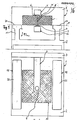
- the basic reference surface section 27 can serve to support a relatively large rectangular workpiece block 80, as shown in FIGS. 11 and 12.
- the block is set up in the machine by resting on the basic reference surface section 27 in the Z direction and by resting its side surface 82 on the side surface 36 in the X direction.
- the workpiece block 80 can be held in place by a plurality of clamps, of which a clamp 90 is shown in section in FIG. 11.
- the clamp 90 has a longitudinal slot 92 through which an elongated bolt 94 extends.
- the elongated bolt 94 penetrates one of the holes in the reference part 30 and is screwed with its threaded section into the associated bore in the carrier 11.
- a support element 96 keeps the end of the clamp 90 pointing away from the workpiece block 80 at a necessary distance from the basic reference surface section 25, and the front finger 98 of the clamp 90 engages over the workpiece block 80.
- FIGS. 10 and 11 the invention is illustrated in FIGS. 10 and 11 on a wire EDM machine in which the carrier 13 extends along two adjacent lateral boundaries of the working area 10 and has the shape of an angle for this purpose. Accordingly, a first reference part 30 is fastened on one leg of the carrier 13 and a second reference part 30 ′ on the other leg of the carrier 13.
- the reference part 30 ' is identical in all details to the reference part 30.
- the workpiece block 80 When the workpiece block 80 is placed in the manner shown in FIGS. 10 and 11 with the side surface 82 against the side surface 36 of the reference part 30 and with the adjacent side surface 84 against the side surface 36 'of the reference part 30', the workpiece block 80 is in X- Direction and in the Y direction aligned in the machine, since in this application the side surface 36 'represents a Y reference.
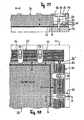
- the meaning of the inclined surface 39 of the reference part 30 as an X reference for secondary reference parts or holding parts results from FIGS. 8, 9 and 12, 13.
- the reference part 20 is fastened on the basic reference surface 20 of the carrier 11 in the manner described, so that the same basic reference surface sections 25, 27 remain free on both sides.
- a secondary reference part 13 consists essentially of an angle, one leg of which has a flat lower surface into which a swallow tail groove is cut. With the lower surface, the secondary reference part 13, comprising the reference part 30, rests on the basic reference surface sections 25 and 27, a counter-reference surface in the dovetail groove enclosing the inclined surface 39.
- the secondary reference part 13 is thus aligned on the one hand in the X direction, namely by the counter reference surface in the dovetail groove against the inclined surface 39, and on the other hand aligned in the Z direction, namely by contacting the lower surface of the secondary reference part 13 on the basic reference surface sections 25, 27.
- a rail running in the Z direction is formed on the upright, other leg of the secondary reference part 13, on which a holder 14 is mounted so as to be displaceable in the Z direction.
- the holder 14 can contain, for example, hydraulic chucks on its free front, in which an electrode holder with a raw electrode to be machined is clamped according to DE-PS 26 46 951.
- the secondary reference part 13 also has a stop 16 which limits the downward movement of the holder 14.
- the stop surface of the stop 16 lies exactly in the zero line and thus in the plane of the basic reference surface sections 25 and 27. It can be seen that in this way, by means of the reference system according to the invention, the workpiece clamped in the holder 14 by simply placing the secondary reference part 13 against the reference part 30 in Working area can be positioned exactly in the Z direction and in the X direction.
- FIG. 8 Another embodiment is shown in FIG. 8, in which a secondary holder 17 in the form of a bridge with the reference part 30 and a similar further reference part 30 ', which is mounted on the base reference surface 22 in the manner described.
- the bridge 17 is provided on the underside with bearing strips 18 on which a smaller workpiece can be positioned exactly in the working area of the machine.
- the inclined surfaces 39 of the reference part 30 and 39 'of the reference part 30' serve as reference surfaces in the X direction.
- the essentially dovetail-shaped cross-sectional profile of the reference part 30 thus has the advantage that secondary reference or holding parts, which are provided with a corresponding dovetail groove on their counter-reference surfaces, can be used without further ado.
- Such secondary reference and holding parts are usually used in other wire spark erosion machines, in which the basic reference surface lies below the zero line.
- FIGS. 12 and 13 show a further possibility of creating a Y reference on the reference part 30.
- a fixed stop 60 can be provided, which has the shape of a metal sleeve.
- the sleeve can be inserted into the extension of one of the through holes 42, 44, 46 of the reference part 30 without play. With its upper casing section, the sleeve protrudes upward above the surface 34 of the reference part.
- the sleeve is held by a bolt 62 which engages in the associated bore in the carrier 13.
- the outer circumference of the upper jacket section of the sleeve 60 thus represents a stop line as a Y reference.
- a slide 64 which can be moved on the reference part 30 and which is operated by a clamp can be used screw 66 can be clamped anywhere on the reference part 30.
- Each of the opposite side surfaces 67, 68, which extend across the longitudinal extent of the reference part 30, can serve as a Y reference, such as the stop surface 52 of the extension 50.
- the tab 64 is provided on its underside with a dovetail groove (not shown) and has counter-reference surfaces with which, on the one hand, it rests on the basic reference surface sections 25 and 27 and, on the other hand, it rests against the inclined surface 39 after tightening the clamping screw 66.
- An end face 65 of the tab 64 can coincide with the lateral boundary of the work area and thus form an X reference.
- FIGS. 11 to 13 also show that the reference part 30 can have a second end face 38 on the side opposite the end face 36, which runs parallel to the first end face 36.
- the reference part thus has a symmetrical cross section, so that both the first side surface 36 and the second side surface 38 and the first inclined surface 39 and the second inclined surface 37 can each be used as an X reference in the sense described above, if required.
Landscapes
- Engineering & Computer Science (AREA)
- Mechanical Engineering (AREA)
- Chemical & Material Sciences (AREA)
- Chemical Kinetics & Catalysis (AREA)
- Electrochemistry (AREA)
- Electrical Discharge Machining, Electrochemical Machining, And Combined Machining (AREA)
Priority Applications (3)
| Application Number | Priority Date | Filing Date | Title |
|---|---|---|---|
| DE8612663U DE8612663U1 (de) | 1985-05-21 | 1986-05-09 | Halte- und Referenzteil für eine Draht-Funkenerosionsmaschine |
| US06/865,136 US4786776A (en) | 1985-05-21 | 1986-05-20 | Holding and reference system for a wire spark-erosion machine |
| JP61118360A JP2566922B2 (ja) | 1985-05-21 | 1986-05-21 | 基準部材を備えた装置 |
Applications Claiming Priority (2)
| Application Number | Priority Date | Filing Date | Title |
|---|---|---|---|
| SE8502488A SE456229B (sv) | 1985-05-21 | 1985-05-21 | Hallar- och referenssystem i en tradgnistningsmaskin |
| SE8502488 | 1985-05-21 |
Publications (3)
| Publication Number | Publication Date |
|---|---|
| EP0202452A2 true EP0202452A2 (fr) | 1986-11-26 |
| EP0202452A3 EP0202452A3 (en) | 1988-07-27 |
| EP0202452B1 EP0202452B1 (fr) | 1991-12-11 |
Family
ID=20360286
Family Applications (1)
| Application Number | Title | Priority Date | Filing Date |
|---|---|---|---|
| EP19860104898 Expired - Lifetime EP0202452B1 (fr) | 1985-05-21 | 1986-04-10 | Système de fixation et de repérage pour une machine d'électroérosion à fil |
Country Status (3)
| Country | Link |
|---|---|
| EP (1) | EP0202452B1 (fr) |
| DE (1) | DE3682818D1 (fr) |
| SE (1) | SE456229B (fr) |
Cited By (1)
| Publication number | Priority date | Publication date | Assignee | Title |
|---|---|---|---|---|
| DE19937635C1 (de) * | 1999-08-12 | 2000-10-26 | System 3R International Ab Vae | Werkstück mit Referenzelementen |
Citations (2)
| Publication number | Priority date | Publication date | Assignee | Title |
|---|---|---|---|---|
| DE2646951A1 (de) | 1976-10-18 | 1978-04-20 | Boerje Ramsbro | Befestigungseinrichtung fuer werkzeuge bzw. werkzeughalter mit zylindrischem schaft |
| SE454491B (sv) | 1984-03-23 | 1988-05-09 | 3R Management Ab | Referenssystem vid en tradgnistningsmaskin |
Family Cites Families (1)
| Publication number | Priority date | Publication date | Assignee | Title |
|---|---|---|---|---|
| US3622145A (en) * | 1968-04-19 | 1971-11-23 | Edwin W Glbson | Work-positioning member |
-
1985
- 1985-05-21 SE SE8502488A patent/SE456229B/sv not_active IP Right Cessation
-
1986
- 1986-04-10 EP EP19860104898 patent/EP0202452B1/fr not_active Expired - Lifetime
- 1986-04-10 DE DE8686104898T patent/DE3682818D1/de not_active Revoked
Patent Citations (2)
| Publication number | Priority date | Publication date | Assignee | Title |
|---|---|---|---|---|
| DE2646951A1 (de) | 1976-10-18 | 1978-04-20 | Boerje Ramsbro | Befestigungseinrichtung fuer werkzeuge bzw. werkzeughalter mit zylindrischem schaft |
| SE454491B (sv) | 1984-03-23 | 1988-05-09 | 3R Management Ab | Referenssystem vid en tradgnistningsmaskin |
Cited By (3)
| Publication number | Priority date | Publication date | Assignee | Title |
|---|---|---|---|---|
| DE19937635C1 (de) * | 1999-08-12 | 2000-10-26 | System 3R International Ab Vae | Werkstück mit Referenzelementen |
| EP1075895A3 (fr) * | 1999-08-12 | 2002-07-03 | System 3R International AB | Pièce avec éléments de référence |
| DE19937635C5 (de) * | 1999-08-12 | 2007-02-01 | System 3R International Ab | Werkstück mit Referenzelementen |
Also Published As
| Publication number | Publication date |
|---|---|
| EP0202452B1 (fr) | 1991-12-11 |
| SE8502488D0 (sv) | 1985-05-21 |
| SE8502488L (sv) | 1986-11-22 |
| SE456229B (sv) | 1988-09-19 |
| EP0202452A3 (en) | 1988-07-27 |
| DE3682818D1 (de) | 1992-01-23 |
Similar Documents
| Publication | Publication Date | Title |
|---|---|---|
| DE19739059A1 (de) | Halteplatte für ein Werkstück | |
| DE69516971T2 (de) | Halterungsvorrichtung | |
| DE102006033625B4 (de) | Bohrverfahren | |
| DE3719167C1 (de) | Numerisch gesteuerte Leiterplatten-Bearbeitungsmaschine | |
| DE9007812U1 (de) | Mehrspindelmaschine zum Bohren, Fräsen o.dgl. | |
| EP0637482B2 (fr) | Procédé de positionnement d'un porte-pièce dans une machine d'usinage, ainsi que porte-pièce correspondant | |
| DE3112417C2 (de) | Vorrichtung zum Einstellen der Schneide eines in einen Werkzeughalter eingesetzten Werkzeuges außerhalb einer Werkzeugmaschine oder zum Messen der Schneidenlage | |
| DE8612663U1 (de) | Halte- und Referenzteil für eine Draht-Funkenerosionsmaschine | |
| EP0310967A2 (fr) | Dispositif de serrage | |
| DE3530783A1 (de) | Kombinierte anlage fuer die elektroerosion mittels draht und werkzeug | |
| EP0513664B1 (fr) | Machine d'usinage, en particulier d'usinage par électroérosion, et procédé d'usinage de pièces | |
| DE2632922A1 (de) | Anwendung einer positioniereinrichtung | |
| AT506161B1 (de) | Vorrichtung zum aufspannen von werkstücken | |
| WO1990000955A1 (fr) | Palette | |
| DE8330451U1 (de) | Wechselpalette | |
| EP0202452B1 (fr) | Système de fixation et de repérage pour une machine d'électroérosion à fil | |
| DE3246533C2 (fr) | ||
| DE3930463C2 (fr) | ||
| EP0538642B1 (fr) | Procédé pour l'abloquage, avec une longueur libre déterminée, d'un foret ou d'une fraise d'une perçeuse à circuits imprimés dans la broche équipée d'une pince étau de cette machine | |
| DE3005639A1 (de) | Spannvorrichtung bei funkenerosiven werkzeugmaschinen o.dgl. | |
| CH624329A5 (en) | Method of clamping a workpiece in order to machine or inspect it, and clamping body for carrying out the method | |
| DE19907100B4 (de) | Vorrichtung zum Positionieren eines Werkzeuges oder Werkstückes an einer Werkzeugmaschine | |
| DE4013029C2 (fr) | ||
| EP4678331A2 (fr) | Dispositif d'alignement | |
| DE3709643A1 (de) | Vorrichtungsplatte |
Legal Events
| Date | Code | Title | Description |
|---|---|---|---|
| PUAI | Public reference made under article 153(3) epc to a published international application that has entered the european phase |
Free format text: ORIGINAL CODE: 0009012 |
|
| AK | Designated contracting states |
Kind code of ref document: A2 Designated state(s): CH DE LI SE |
|
| PUAL | Search report despatched |
Free format text: ORIGINAL CODE: 0009013 |
|
| AK | Designated contracting states |
Kind code of ref document: A3 Designated state(s): CH DE LI SE |
|
| 17P | Request for examination filed |
Effective date: 19881017 |
|
| 17Q | First examination report despatched |
Effective date: 19900517 |
|
| GRAA | (expected) grant |
Free format text: ORIGINAL CODE: 0009210 |
|
| AK | Designated contracting states |
Kind code of ref document: B1 Designated state(s): CH DE LI SE |
|
| REF | Corresponds to: |
Ref document number: 3682818 Country of ref document: DE Date of ref document: 19920123 |
|
| PLBI | Opposition filed |
Free format text: ORIGINAL CODE: 0009260 |
|
| 26 | Opposition filed |
Opponent name: BUECHLER B-SET AG Effective date: 19920911 |
|
| PGFP | Annual fee paid to national office [announced via postgrant information from national office to epo] |
Ref country code: DE Payment date: 19940225 Year of fee payment: 9 |
|
| PGFP | Annual fee paid to national office [announced via postgrant information from national office to epo] |
Ref country code: SE Payment date: 19940422 Year of fee payment: 9 |
|
| PGFP | Annual fee paid to national office [announced via postgrant information from national office to epo] |
Ref country code: CH Payment date: 19940519 Year of fee payment: 9 |
|
| RDAG | Patent revoked |
Free format text: ORIGINAL CODE: 0009271 |
|
| STAA | Information on the status of an ep patent application or granted ep patent |
Free format text: STATUS: PATENT REVOKED |
|
| EUG | Se: european patent has lapsed |
Ref document number: 86104898.1 Effective date: 19950301 |
|
| REG | Reference to a national code |
Ref country code: CH Ref legal event code: PL |
|
| 27W | Patent revoked |
Effective date: 19941015 |
|
| PLAB | Opposition data, opponent's data or that of the opponent's representative modified |
Free format text: ORIGINAL CODE: 0009299OPPO |