EP0202003A2 - Méthode et dispositif de mesure de la différence de temps de propagation et/ou du gain - Google Patents
Méthode et dispositif de mesure de la différence de temps de propagation et/ou du gain Download PDFInfo
- Publication number
- EP0202003A2 EP0202003A2 EP86302190A EP86302190A EP0202003A2 EP 0202003 A2 EP0202003 A2 EP 0202003A2 EP 86302190 A EP86302190 A EP 86302190A EP 86302190 A EP86302190 A EP 86302190A EP 0202003 A2 EP0202003 A2 EP 0202003A2
- Authority
- EP
- European Patent Office
- Prior art keywords
- signal
- amplitude
- channels
- repetitive
- signals
- Prior art date
- Legal status (The legal status is an assumption and is not a legal conclusion. Google has not performed a legal analysis and makes no representation as to the accuracy of the status listed.)
- Withdrawn
Links
Images
Classifications
-
- H—ELECTRICITY
- H04—ELECTRIC COMMUNICATION TECHNIQUE
- H04N—PICTORIAL COMMUNICATION, e.g. TELEVISION
- H04N17/00—Diagnosis, testing or measuring for television systems or their details
Definitions
- This invention relates to a method and apparatus for measuring delay and/or gain difference.
- differences in delay and/or gain between two signal transmission channels are measured by impressing on each channel a repetitive signal comprising a burst packet.
- the two burst packets are of different predetermined frequencies and are timed to have a predetermined phase relationship at a selected time during each burst packet.
- the two signals that have been transmitted through the signal transmission channels respectively are additively combined, and depending upon whether it is the gain or delay of the channels that is to be measured, the amplitude of the combined signal at a turning point in the amplitude of the signal envelope or the difference, if any, between the selected time (at which the packets have the predetermined phase relationship) and the time at which a turning point in the amplitude of the envelope occurs, is measured.
- the burst packets occur at line rate and the two signals are synchronized so that the burst packets are in phase at the midpoint of the line.
- the output signals are subtracted and the difference signal is displayed on an oscilloscope, or the output signals are applied to the A and B terminals of a waveform monitor in the A-B mode. If the two channels are of equal delay and gain, the envelope signal will have zero amplitude at the midpoint of the line. If the gains are unequal, the turning point of the envelope amplitude will occur at a finite value of the envelope amplitude, and if the delays are different the turning point of the envelope amplitude will be displaced from the midpoint of the line.
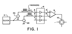
- the measurement system illustrated in FIG. 1 comprises a pair of video signal generators 2A and 2B.
- the two video signal generators are digital, each comprising a PROM that is programmed to produce a predetermined signal when the PROM is addressed.
- the two video signal generators 2A and 2B receive their clocks from a common master clock generator 4.
- the signal generated by each generator repeats at video line rate and includes a blanking interval and a full line burst packet on a pedestal.
- the two burst packets are at slightly . different frequencies (e. g. 500 kHz and 502 kHz) and are timed to be in phase in the middle of the video line.
- the two test signals are applied to the inputs A and B of two of the three channels of an analog component video system 6, and the signals at the outputs A' and B' are applied to respective inputs of a subtraction amplifier 8 that combines the signals in additive fashion.
- the output of the amplifier 8 is applied to the vertical input of a waveform monitor or other suitable display device, such as an oscilloscope.
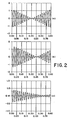
- FIG. 2(a) shows the display that is obtained when the burst packets are at 500 kHz and 510 kHz and there is no gain or delay difference between the two channels.
- the envelope of the combined signal then has zero amplitude at the midpoint of the horizontal line.
- the burst packets are at 500 kHz and at 510 kHz, and again the envelope of the combined signal has a point of zero amplitude, but this is spaced from the midpoint of the line, implying a delay difference between the channels.
- T is 5 us/division and this corresponds, in the case of FIGS. 2(a) and 2(b) to approximately 100 ns delay per division.
- FIG. 2(c) shows the display that is obtained with signals of 500 kHz and 502 kHz. This results in a calibration of about 20 ns delay per division.
- the two signals do not cancel completely, and accordingly the envelope has non-zero amplitude at its minimum amplitude point.
- the amplitude of the envelope at its minimum amplitude point represents a gain difference of about 5%.
- the minimum amplitude point is spaced from the midpoint of the line by about two and one-half divisions, corresponding to a delay of 50 ns between the channels.
- the blanking interval for the luminance component would include a horizontal sync pulse but it would not be necessary to include a horizontal sync pulse in the blanking intervals for the color difference components.
- one of the test signals could include markers (see FIG. 1) that are spaced apart along the line and provide the timing calibration independently of the calibration of the display. Markers of different height could be employed to provide a calibration of gain difference.
Landscapes
- Engineering & Computer Science (AREA)
- Health & Medical Sciences (AREA)
- Biomedical Technology (AREA)
- General Health & Medical Sciences (AREA)
- Multimedia (AREA)
- Signal Processing (AREA)
- Testing, Inspecting, Measuring Of Stereoscopic Televisions And Televisions (AREA)
- Measurement Of Resistance Or Impedance (AREA)
Applications Claiming Priority (2)
| Application Number | Priority Date | Filing Date | Title |
|---|---|---|---|
| US06/722,943 US4829366A (en) | 1985-04-12 | 1985-04-12 | Method and apparatus for measuring delay and/or gain difference using two different frequency sources |
| US722943 | 1985-04-12 |
Publications (2)
| Publication Number | Publication Date |
|---|---|
| EP0202003A2 true EP0202003A2 (fr) | 1986-11-20 |
| EP0202003A3 EP0202003A3 (fr) | 1988-09-14 |
Family
ID=24904093
Family Applications (1)
| Application Number | Title | Priority Date | Filing Date |
|---|---|---|---|
| EP86302190A Withdrawn EP0202003A3 (fr) | 1985-04-12 | 1986-03-25 | Méthode et dispositif de mesure de la différence de temps de propagation et/ou du gain |
Country Status (6)
| Country | Link |
|---|---|
| US (1) | US4829366A (fr) |
| EP (1) | EP0202003A3 (fr) |
| JP (1) | JPS6254173A (fr) |
| AU (1) | AU566220B2 (fr) |
| CA (1) | CA1272508A (fr) |
| DK (1) | DK165286A (fr) |
Cited By (1)
| Publication number | Priority date | Publication date | Assignee | Title |
|---|---|---|---|---|
| DE3900531A1 (de) * | 1988-01-11 | 1989-07-27 | Tektronix Inc | Anzeigevorrichtung fuer die messung des verzoegerungs- und verstaerkungsverhaeltnisses von chrominanz zu luminanz |
Families Citing this family (7)
| Publication number | Priority date | Publication date | Assignee | Title |
|---|---|---|---|---|
| US5010403A (en) * | 1990-04-12 | 1991-04-23 | Tektronix, Inc. | Measurement of timebase jitter for component video |
| US6124897A (en) * | 1996-09-30 | 2000-09-26 | Sigma Designs, Inc. | Method and apparatus for automatic calibration of analog video chromakey mixer |
| US5528309A (en) * | 1994-06-28 | 1996-06-18 | Sigma Designs, Incorporated | Analog video chromakey mixer |
| US7180537B2 (en) * | 2004-02-18 | 2007-02-20 | Tektronix, Inc. | Relative channel delay measurement |
| JP4980602B2 (ja) * | 2005-10-12 | 2012-07-18 | 株式会社エヌ・ティ・ティ・ドコモ | 伝搬遅延時間差を測定するための送信機および受信機 |
| JP2023090138A (ja) * | 2021-12-17 | 2023-06-29 | アストロデザイン株式会社 | 遅延時間測定方法および遅延時間測定装置 |
| CN114778915B (zh) * | 2022-03-16 | 2025-06-27 | 中电科思仪科技股份有限公司 | 一种减小数字示波器高阻通道输入电容的电路及方法 |
Family Cites Families (7)
| Publication number | Priority date | Publication date | Assignee | Title |
|---|---|---|---|---|
| US2333322A (en) * | 1940-02-22 | 1943-11-02 | Int Standard Electric Corp | Apparatus for measuring phase differences and for analogous purposes |
| NL298287A (fr) * | 1962-09-24 | |||
| GB1100655A (en) * | 1965-09-20 | 1968-01-24 | Marconi Instruments Ltd | Improvements in or relating to cathode ray tube display oscilloscope instruments |
| US3441843A (en) * | 1966-06-08 | 1969-04-29 | Claire R Wainwright | System for tilting frequency marker in sweep generator display |
| US3706931A (en) * | 1971-04-01 | 1972-12-19 | Bell Telephone Labor Inc | Apparatus for use in measuring phase dispersion produced by apparatus or a system |
| US3986113A (en) * | 1973-11-23 | 1976-10-12 | Hewlett-Packard Company | Two channel test instrument with active electronicphase shift means |
| DE3025971C2 (de) * | 1980-07-09 | 1984-03-08 | Institut für Rundfunktechnik GmbH, 8000 München | Verfahren zur Messung von Amplituden- und/oder Phasenverzerrungen eines FM-Übertragungssystems |
-
1985
- 1985-04-12 US US06/722,943 patent/US4829366A/en not_active Expired - Lifetime
-
1986
- 1986-03-25 EP EP86302190A patent/EP0202003A3/fr not_active Withdrawn
- 1986-04-10 CA CA000506331A patent/CA1272508A/fr not_active Expired - Fee Related
- 1986-04-11 DK DK165286A patent/DK165286A/da not_active IP Right Cessation
- 1986-04-11 AU AU56025/86A patent/AU566220B2/en not_active Ceased
- 1986-04-11 JP JP61083968A patent/JPS6254173A/ja active Pending
Cited By (1)
| Publication number | Priority date | Publication date | Assignee | Title |
|---|---|---|---|---|
| DE3900531A1 (de) * | 1988-01-11 | 1989-07-27 | Tektronix Inc | Anzeigevorrichtung fuer die messung des verzoegerungs- und verstaerkungsverhaeltnisses von chrominanz zu luminanz |
Also Published As
| Publication number | Publication date |
|---|---|
| CA1272508A (fr) | 1990-08-07 |
| JPS6254173A (ja) | 1987-03-09 |
| US4829366A (en) | 1989-05-09 |
| AU566220B2 (en) | 1987-10-15 |
| AU5602586A (en) | 1986-10-16 |
| DK165286A (da) | 1986-10-13 |
| EP0202003A3 (fr) | 1988-09-14 |
| DK165286D0 (da) | 1986-04-11 |
Similar Documents
| Publication | Publication Date | Title |
|---|---|---|
| US4829366A (en) | Method and apparatus for measuring delay and/or gain difference using two different frequency sources | |
| EP0090426A2 (fr) | Procédé et dispositif pour mesurer le rapport de phase entre synchronisation horizontale et sous-porteuse | |
| US2885470A (en) | Television transmission quality testing system | |
| US5010403A (en) | Measurement of timebase jitter for component video | |
| US3825835A (en) | Signal-to-noise ratio measurement | |
| GB1191256A (en) | Apparatus for measuring a characteristic of a repetitively varying electrical signal | |
| US4204228A (en) | Digital testing apparatus | |
| US4680620A (en) | Measurement of SC/H phase using a subcarrier time mark generator and a calibrated phase shifter | |
| US4069500A (en) | Arrangements for testing color television systems | |
| US4603346A (en) | Subcarrier/horizontal sync phase measurement | |
| US2855515A (en) | Television test apparatus | |
| US4635094A (en) | Method and apparatus for measurement of component video signal characteristics using an oscilloscope | |
| US4587551A (en) | Measurement of SC/H phase | |
| US4149044A (en) | Method and apparatus for graphically displaying amplitude and phase jitter | |
| EP0162236B1 (fr) | Mesure de la phase de la porteuse couleur et/ou de l'impulsion de synchronisation de lignes utilisant un dispositif d'affichage en coordonnées polaires | |
| US3250853A (en) | Color-television test signal generator | |
| US4123705A (en) | Oscillographic apparatus for measuring the magnitude and duration and for separately viewing an input signal | |
| JP2870874B2 (ja) | 相対遅延を測定する方法及び装置 | |
| Teear et al. | Measurement techniques in television studios and outside broadcasts | |
| SU946010A1 (ru) | Устройство дл измерени параметров трактов цветного телевидени | |
| GB949072A (en) | Apparatus for comparing amplitudes at selected points in recurrent electrical signal waveforms | |
| CA1256196A (fr) | Mesure de la phase entre le sous-porteuse et de signal de synchronisation horizontale au moyen d'un affichage polaire | |
| SU803127A1 (ru) | Способ измерени расхождени воВРЕМЕНи СигНАлОВ РКОСТи и цВЕТНОСТиВ ТЕлЕВизиОННыХ TPAKTAX | |
| JPS6238393Y2 (fr) | ||
| Sproul | A video visual measuring set with sync pulses |
Legal Events
| Date | Code | Title | Description |
|---|---|---|---|
| PUAI | Public reference made under article 153(3) epc to a published international application that has entered the european phase |
Free format text: ORIGINAL CODE: 0009012 |
|
| AK | Designated contracting states |
Kind code of ref document: A2 Designated state(s): DE FR GB NL |
|
| PUAL | Search report despatched |
Free format text: ORIGINAL CODE: 0009013 |
|
| AK | Designated contracting states |
Kind code of ref document: A3 Designated state(s): DE FR GB NL |
|
| 17P | Request for examination filed |
Effective date: 19881122 |
|
| STAA | Information on the status of an ep patent application or granted ep patent |
Free format text: STATUS: THE APPLICATION HAS BEEN WITHDRAWN |
|
| 18W | Application withdrawn |
Withdrawal date: 19910221 |
|
| RIN1 | Information on inventor provided before grant (corrected) |
Inventor name: PENNEY, BRUCE J. |