EP0201639A1 - Dispositif de changement de vitesse automatique pour bicyclettes - Google Patents
Dispositif de changement de vitesse automatique pour bicyclettes Download PDFInfo
- Publication number
- EP0201639A1 EP0201639A1 EP85303424A EP85303424A EP0201639A1 EP 0201639 A1 EP0201639 A1 EP 0201639A1 EP 85303424 A EP85303424 A EP 85303424A EP 85303424 A EP85303424 A EP 85303424A EP 0201639 A1 EP0201639 A1 EP 0201639A1
- Authority
- EP
- European Patent Office
- Prior art keywords
- fixed
- bicycle
- wheel
- chain
- sliding block
- Prior art date
- Legal status (The legal status is an assumption and is not a legal conclusion. Google has not performed a legal analysis and makes no representation as to the accuracy of the status listed.)
- Withdrawn
Links
Images


Classifications
-
- B—PERFORMING OPERATIONS; TRANSPORTING
- B62—LAND VEHICLES FOR TRAVELLING OTHERWISE THAN ON RAILS
- B62M—RIDER PROPULSION OF WHEELED VEHICLES OR SLEDGES; POWERED PROPULSION OF SLEDGES OR SINGLE-TRACK CYCLES; TRANSMISSIONS SPECIALLY ADAPTED FOR SUCH VEHICLES
- B62M1/00—Rider propulsion of wheeled vehicles
- B62M1/24—Rider propulsion of wheeled vehicles with reciprocating levers, e.g. foot levers
- B62M1/28—Rider propulsion of wheeled vehicles with reciprocating levers, e.g. foot levers characterised by the use of flexible drive members, e.g. chains
Definitions
- the present inventor has found the defects of conventional speed variating means of bicycle and invented the present automatic speed variating means for bicycle.
- a speed variating means for a bicycle includes a reciprocatable actuating means arranged for tensioning a driving chain by lateral deflection thereof, the chain being fixed in position at one end and wherein the resulting stroke of the driving chain is variable by variation of the position of the fixed and of the chain.
- the present invention further provides an automatic speed variating means for bicycle comprising an actuating means, a speed adjusting means and a driving chain wherein the speed adjusting means can be actuated automatically or manually to variate the driving speed of a bicycle.
- the present invention comprises: an actuating means 1, a stroke adjusting means 2, a driving chain 3 and a speed controller 4.
- Actuating means 1 comprises a pedal 11, a pedal rod 12, a pivot 13 pivoted in a bush 13a connected on the bottom fork B of a bicycle, an arcuated driving plate 14 extending from pivot 13 and forming an angle with pedal rod 12, and a lower rod 15 connecting the stroke adjusting means 2.
- Arcuated driving plate 14 has a curvature for the smooth infinitesimal adjustment of stroke adjusting means 2.
- Stroke adjusting means 2 comprises a sliding block 21 formed with a trapezoid hole 22, a side lug 23 having a hole for inserting a link 26, a bracket 24, a chain wheel 25 pivotedly fixed on bracket 24, a link 26 connected with a bottom striker 27.
- Bottom striker 27 is formed with two extensions 27a, 27b, both forming a bending angle therebetween.
- Trapezoid hole 22 is formed with an upper slope surface between edge 22a and edge 22c and a lower flat surface 22b.
- One end 31 of driving chain 3 is fixed on bottom fork B.
- the chain 3 has its one end 31 fixed on bottom fork B and has its remaining portion engaged with chain wheel 25, chain wheel 32 formed on the center of bicycle wheel T, chain wheel 33 and has its final end 36 fixed on bottom fork B.
- Chain wheel 33 is connected with a restored spring 34 which is connected to bush 13a by a bracket 35.
- Speed controller 4 comprises a lower bracket 41 fixed on bottom fork B, a striker trimner 42 pivotedly fixed on bracket 41 and formed with two extensions 42a for receiving striker 27, a central rod 43 extending fromtrimmer 42, a biasing link 44 of which on end is formed as a hook 44a inserted into a lengthy hole 43a of central rod 43 and the uppermost end is formed as a handle 45 for manual speed adjustment and a pivot 44b is centrally connected to the upper fork B' of bottom fork B and a magnetic actuator 46 which is pivotedly connected onto link 44 and connected with a restoned spring 47 secured to upper fork B'.
- Magnetic actuator 46 comprises a magnetic rotor core 46b and an outer stator collar 46a.
- the pedal 11 When driving the bicycle of the present invention, the pedal 11 is depressed to allow the driving rod 14 pulling the driving chain 3 3 in direction D so that the chain wheel 32 will be rotated to drive the bicycle.
- the restored spring 34 When releasing the depression of pedal, the restored spring 34 will retract the driving chain 3 for next driving operation.
- the handle 45 of speed controller 4 can be pulled in direction R1 as Figure 4 shown to biase rod 43 in direction R2 so as to rotate the striker trimmer 42 clockwise.
- the striker 27 of stroke adjusting means 2 After operating the actuating means 1, the striker 27 of stroke adjusting means 2 will backwards ride trimmer 42 at a new position as dotted line shown in Figure 5 and the link 26 will raise the sliding block 21 to a higher position. The higher position the block 21 is set, the faster speed of bicycle will be adjusted.
- This principle is shown in Figure 6 in that L' at the higher position will run longer stroke than the lower one L so as to exert a higher speed.
- the tension caused by spring 34 will exert a force F1 which, however, will act on the arcuated plate 14 at edge 22c so as to biase the sliding block 21 to the position as dotted line shown, the lower edge at point P will exert a counter force f1 to pressurize on arcuated plate 14 so as to prevent from slipping down the block 21 of the present invention.
- the force F1 When depressing the pedal 11 to move the plate 14 in direction D, the force F1 will be increased as bigger tension existing on chain 3 to become greater force F2 which in turn, forms a greater counter force f2 to further prevent from slipping down of sliding block 21.
- the present invention can be provided as dual combination on both sides of the bicycle so that either single side can be operated or both sides be alternatively operated at the same time.
- the present invention can be actuated automatically. If the running speed is getting higher and higher, the magnetic actuator 46 will be rotated faster to produce magnetic force to push link 44 in direction R1 so as to adjust the stroke adjusting means 2 for a higher speed.
- the spring 47 is provided to pressurize the magnetic actuator 46 on the wheel tire T and to tension the link 44 for normal operation.
- a sliding collar 45a with a stopping screw 45b is provided to slide along an arcuated guide 45c for variable speed adjustment.
- another preferred embodiment of the present invention comprises: an actuating means 1 1 , a speed adjusting means 2' and a driving chain 3'.
- Actuating means 1' comprises a pedal 11', a pedal rod 12' having pivot 13' fixed in a bush 13'a on bottom fork B and a driving rod 14' which forms an angle with the rod 12'.
- a chain wheel 32' is rotatably formed atop on the driving rod 14'.
- Speed adjusting means 2' comprises an arcuated plate 21' fixed between the seat tube S and the bottom fork B of a bicycle, a controlling link 23', a sliding block 22' lowerly connected to controlling link 23', a handle 24' upperly formed on link 23', a restored spring 25 1 fixed to the upper fork B' to restore the speed adjusting means 2 1 for normal running and magnetic actuator 26' fixed on the upper portion of link 23'.
- Sliding block 22' is formed with a hole 22a' for jacketing block 22' into arcuated plate 21'.
- a bracket 22b' of block 22' is provided to fix one end 31' of driving chain 3 1.
- a side lug 22'c of block 22' having a hole is provided for the insertion of link 23'.
- Link 23 1 is centrally and pivotedly fixed on the upper fork B 1 of a bicycle by a pivot 23'a.
- the magnetic actuator 26 1 is pressurized on bicycle wheel T as restored by spring 25'.
- Magnetic actuator 26' comprises a rotator core 26'a and a stator collar 26'b. Briefly, the magnetic actuator 26' operates by rotating the stator collar about the rotor core. The rotor core would rotate slightly compared to the faster rotating collar due to the magnetic attraction between the magnetic core and the magnetic collar.
- Driving chain 3 1 has its one end 31' fixed on block 22 1 and has its remaining portion engaged with chain wheel 32' rotatably fixed atop on driving rod 14', a chain wheel 33 1 formed on the center of bicycle wheel T, a chain wheel 34 1 which is connected with a restored spring 35' fixed on bottom fork B by a bracket 36', and has its final end 37' fixed on bottom fork B.
- Handle 24' is adjustably moved along an arcuated guide 24'b and can be stopped by a stopping screw 24'a for manual speed adjustment of the invention.
- the magnetic actuator 26' can be fast rotated if the driving speed is getting higher to exert a greater torque to biase the link 23' in direction R to lower block 22 1 for faster speed adjustment.
- the structure of chain wheel 33 1 is designed as usual sprocket of a conventional bicycle.
- the pedal 11' When driving the bicycle of the present invention, the pedal 11' is depressed to pull the driving chain 3' so that the chain wheel 33' will be rotated to drive the bicycle.
- the restored spring 35' When releasing the depression of pedal, the restored spring 35' will retract the driving chain 3' for next driving operation.
- the invention changes the conventional way for driving a bicycle by treadling the pedal and rotating the chain sprocket to the present way by depressing the pedal 11' to pull chain 3' to move bicycle forwards and by releasing pedal 11' to reverse the driving chain for next moving operation.
- Such a modification of pedal movement is especially designed for the speed variation of the present invention.
- the length of driving chain 3' among block 22 1 , chain wheel 32' and chain wheel 33 1 during moving the block 22' should be always the same.
- the length of La + Lb should be equal to the length of Lc + Ld.
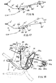
- FIG. 13 through 17 which comprises an actuating means 1", a driving chain 3" and a speed controller 4".
- Actuating means 1" comprises a pedal 11", a pedal rod 12" terminated by a rear pivot 13" pivotedly fixed in a bush 13"a and a driving rod 15" pivotedly formed on pedal rod 12" by a front pivot 15"a positioned beyond the rear pivot 13"a.
- Driving rod 15" is formed with a bracket 15"b for rotatably fixing a chain wheel 32" on the bracket 15"b.
- Driving chain 3" has its one end 31" fixed on the bottom fork B” and has its remaining portion engaged with a chain wheel 32" rotatably fixed atop on driving rod 15", a chain wheel 33" formed on the center of bicycle wheel T, a chain wheel 34" which is connected with a restored spring 35" fixed on bottom fork by a bracket 36", and has its another end 37" fixed onto bottom fork.
- Speed controller 4" comprises a fulcrum adjusting plate 41", a sliding block 42” adjustably sliding on plate 41", a fulcrum wheel 43” rotatably formed on sliding block 42", a link 44" lowerly connected with block 42" and upperly pivotedly connected to seat tube S by a pivot 44"a, a restored spring 46" fixed on the upper fork to restore the controller 4" and a magnetic actuator 45" pivotedly fixed on the upper portion of link 44" and pressurized on wheel tire T as restored by spring 46".
- the driving rod is riding fulcrum wheel 43".
- FIG. 18 is modified from the present invention as shown in Figure 1 to include an actuating means 1, a stroke adjusting means 2, a driving wire 3a and a speed controller 28.
- the original driving chain 3 is modified as a wire 3a of which one end 31a is fixed on the bottom fork B and the remaining wire portion is guided by an idler 25a pivoted on the sliding block 21 and then wound for several turns on the hub 32b of central wheel 32a which is tensioned by a restoring spring 34a secured to the'bottom fork so that once depressing the pedal 11, the driving plate 14 will pull the wire 3a and rotate the wheel 32a as another wire end 36a is fixed on the wheel hub 32b.
- the original speed controller 4 is also modified as the speed controller 28 which includes a first restoring spring 28a securing the sliding block 21 to the pedal rod 12, a wire 28b having one end secured to the sliding block 21 and having the remaining wire guided by an idler 28c fixed atop on driving plate 14 and then secured to a ratchet wheel 28e through a second restoring spring 28d, a ratchet wheel 28e
- each quick depression (D) of pedal 11 will allow the driving plate 14 striking the ratchet wheel 28e to rotate clockwise for a small radians so as to tension the wire 28b in which the tensioning energy is temporarily stored in the second restored spring 28d.
- the tensioning energy of spring 28d will pull the wire 28b to raise sliding block 21 for a little bit of higher speed variation.
- the sliding block 21 will be raised to the highest position stably since the ratchet wheel 28c has been rotated to the non-toothed portion 28'e on ratchet perimeter. The highest speed variation can thus be achieved.
- the catch 28f is unlocked to release the ratchet wheel 28e as restored by spring 28i so that the first restoring spring 28a will pull the sliding block 21 to its lowest position for normal running.
- the trapezoid hole 22 may be modified as other shapes and a lining or packing plate may be further provided to embed the hole 22 to prevent from wearing the arcuate plate 14.
Landscapes
- Engineering & Computer Science (AREA)
- Chemical & Material Sciences (AREA)
- Combustion & Propulsion (AREA)
- Transportation (AREA)
- Mechanical Engineering (AREA)
- Transmission Devices (AREA)
Applications Claiming Priority (1)
| Application Number | Priority Date | Filing Date | Title |
|---|---|---|---|
| US06/501,656 US4549874A (en) | 1983-06-06 | 1983-06-06 | Automatic speed variating means for bicycle |
Publications (1)
| Publication Number | Publication Date |
|---|---|
| EP0201639A1 true EP0201639A1 (fr) | 1986-11-20 |
Family
ID=23994485
Family Applications (1)
| Application Number | Title | Priority Date | Filing Date |
|---|---|---|---|
| EP85303424A Withdrawn EP0201639A1 (fr) | 1983-06-06 | 1985-05-15 | Dispositif de changement de vitesse automatique pour bicyclettes |
Country Status (2)
| Country | Link |
|---|---|
| US (1) | US4549874A (fr) |
| EP (1) | EP0201639A1 (fr) |
Cited By (2)
| Publication number | Priority date | Publication date | Assignee | Title |
|---|---|---|---|---|
| WO1991008136A1 (fr) * | 1989-11-23 | 1991-06-13 | Werner Stahl | Trottinette |
| EP2679480A1 (fr) * | 2012-06-26 | 2014-01-01 | Graditech Entwicklungs GmbH | Véhicule |
Families Citing this family (21)
| Publication number | Priority date | Publication date | Assignee | Title |
|---|---|---|---|---|
| US4549874A (en) * | 1983-06-06 | 1985-10-29 | Maz Wen | Automatic speed variating means for bicycle |
| US4713042A (en) * | 1986-03-24 | 1987-12-15 | Daniel Imhoff | Automatic transmission for a bicycle |
| US5256110A (en) * | 1991-05-13 | 1993-10-26 | Olsen William K | Continuous infinite-ratio power transmission device |
| US5988662A (en) * | 1997-06-09 | 1999-11-23 | Volunteers For Medical Engineering | Lever driven bicycle |
| US6551210B2 (en) | 2000-10-24 | 2003-04-22 | Motion Technologies, Llc. | Continuously variable transmission |
| US7753386B2 (en) * | 2002-03-20 | 2010-07-13 | Robert Drymalski | Steering mechanism and method for a manually powered vehicle |
| US7195264B2 (en) * | 2002-03-20 | 2007-03-27 | Robert Drymalski | Manually powered vehicle having improved steering |
| US6764089B2 (en) * | 2002-03-20 | 2004-07-20 | Robert Drymalski | Manually powered drive mechanism and vehicle employing same |
| US7510201B2 (en) * | 2004-04-16 | 2009-03-31 | Rashad Na'im Scarborough | Lever enhanced pedaling system |
| US20070202976A1 (en) * | 2005-10-18 | 2007-08-30 | Daren Luedtke | Power regeneration system with electromagnetic variable speed control |
| KR101422475B1 (ko) | 2005-11-22 | 2014-07-28 | 폴브룩 인텔렉츄얼 프로퍼티 컴퍼니 엘엘씨 | 연속 가변 변속기를 구비한 자전거 |
| US7882762B2 (en) | 2006-01-30 | 2011-02-08 | Fallbrook Technologies Inc. | System for manipulating a continuously variable transmission |
| US20080070729A1 (en) * | 2006-05-11 | 2008-03-20 | Fallbrook Technologies Inc. | Continuously variable drivetrain |
| US20080272596A1 (en) * | 2007-05-02 | 2008-11-06 | House Edward T | Wind turbine variable speed transmission |
| WO2009065057A2 (fr) * | 2007-11-15 | 2009-05-22 | Fallbrook Technologies Inc. | Transmission variable en continu |
| CA2708634C (fr) | 2007-12-21 | 2017-08-01 | Fallbrook Technologies Inc. | Transmissions automatiques et procedes correspondants |
| US7862062B2 (en) * | 2008-02-08 | 2011-01-04 | Bravo Sports | Non-motorized vehicle |
| CN102084155B (zh) | 2008-06-23 | 2014-06-11 | 福博科知识产权有限责任公司 | 无级变速器 |
| WO2010120933A1 (fr) | 2009-04-16 | 2010-10-21 | Fallbrook Technologies Inc. | Ensemble stator et mécanisme de changement de vitesse pour une transmission à variation continue |
| JP4589446B1 (ja) * | 2009-10-21 | 2010-12-01 | 時雄 中川 | 2本のテコを用いた人力駆動装置及びそれを備えた人力駆動車両 |
| KR102433297B1 (ko) | 2013-04-19 | 2022-08-16 | 폴브룩 인텔렉츄얼 프로퍼티 컴퍼니 엘엘씨 | 무단 변속기 |
Citations (4)
| Publication number | Priority date | Publication date | Assignee | Title |
|---|---|---|---|---|
| DE103792C (fr) * | ||||
| DE92497C (fr) * | ||||
| FR2465633A1 (fr) * | 1979-09-21 | 1981-03-27 | Charrier Marcel | Systeme de pedalage a tres haut rendement |
| US4549874A (en) * | 1983-06-06 | 1985-10-29 | Maz Wen | Automatic speed variating means for bicycle |
Family Cites Families (4)
| Publication number | Priority date | Publication date | Assignee | Title |
|---|---|---|---|---|
| US636184A (en) * | 1898-11-09 | 1899-10-31 | Axel Fredrik Abrahamson Roxendorff | Automatic variable driving-gear for velocipedes. |
| DE2027885B2 (de) * | 1970-06-06 | 1978-12-07 | Daimler-Benz Ag, 7000 Stuttgart | Radaufhängung für Kraftfahrzeuge |
| US3913945A (en) * | 1974-05-01 | 1975-10-21 | Marion A Clark | Bicycle with variable speed lever action drive |
| US3954282A (en) * | 1974-07-15 | 1976-05-04 | Hege Advanced Systems Corporation | Variable speed reciprocating lever drive mechanism |
-
1983
- 1983-06-06 US US06/501,656 patent/US4549874A/en not_active Expired - Fee Related
-
1985
- 1985-05-15 EP EP85303424A patent/EP0201639A1/fr not_active Withdrawn
Patent Citations (4)
| Publication number | Priority date | Publication date | Assignee | Title |
|---|---|---|---|---|
| DE103792C (fr) * | ||||
| DE92497C (fr) * | ||||
| FR2465633A1 (fr) * | 1979-09-21 | 1981-03-27 | Charrier Marcel | Systeme de pedalage a tres haut rendement |
| US4549874A (en) * | 1983-06-06 | 1985-10-29 | Maz Wen | Automatic speed variating means for bicycle |
Cited By (2)
| Publication number | Priority date | Publication date | Assignee | Title |
|---|---|---|---|---|
| WO1991008136A1 (fr) * | 1989-11-23 | 1991-06-13 | Werner Stahl | Trottinette |
| EP2679480A1 (fr) * | 2012-06-26 | 2014-01-01 | Graditech Entwicklungs GmbH | Véhicule |
Also Published As
| Publication number | Publication date |
|---|---|
| US4549874A (en) | 1985-10-29 |
Similar Documents
| Publication | Publication Date | Title |
|---|---|---|
| EP0201639A1 (fr) | Dispositif de changement de vitesse automatique pour bicyclettes | |
| US5213005A (en) | Speed control device for bicycle derailleur | |
| US4279172A (en) | Derailleur for a bicycle | |
| US9802671B2 (en) | Control device for a bicycle derailleur | |
| US6619154B2 (en) | Electrical control device for a motor-driven derailleur for bicycles | |
| US4198873A (en) | Speed changing device for a bicycle and the like | |
| EP0006021B1 (fr) | Dérailleur | |
| JP2009523652A (ja) | 自転車のディレイラ用の制御装置 | |
| EP2074014B1 (fr) | Bicyclette à large plage de puissance avec système de changement de vitesse intuitif positif | |
| JPH0829744B2 (ja) | 多段変速自転車のためのディレイラー | |
| US4421334A (en) | High speed cycle | |
| US6718844B2 (en) | Twist-grip shift control device for a bicycle | |
| US4816008A (en) | Variable-ratio transmissions, separately and in bicycles | |
| US4889354A (en) | Eccentrically operating speed-variating means for bicycle | |
| US4887990A (en) | Gear-shift control bicycles and similar vehicles | |
| JP2007008458A (ja) | 自転車のディレーラの制御デバイス | |
| US4322209A (en) | Derailleur with improved mechanism for moving and retaining a movable member to and in a desired speed change stage | |
| US6471610B1 (en) | Front derailleur for a bicycle | |
| US4285419A (en) | Brake clutch release control for belt driven riding mowers | |
| US20160114858A1 (en) | Variably expanding chain transmission | |
| US5302155A (en) | Bicycle derailleur | |
| KR100822308B1 (ko) | 다단 기어자전거의 자동변속기 | |
| US4925201A (en) | Variable-ratio transmissions, separately and in bicycles | |
| CN205632877U (zh) | 自行车控制装置 | |
| US6142264A (en) | Brake device for children's vehicle |
Legal Events
| Date | Code | Title | Description |
|---|---|---|---|
| PUAI | Public reference made under article 153(3) epc to a published international application that has entered the european phase |
Free format text: ORIGINAL CODE: 0009012 |
|
| AK | Designated contracting states |
Kind code of ref document: A1 Designated state(s): AT BE CH DE FR GB IT LI LU NL SE |
|
| STAA | Information on the status of an ep patent application or granted ep patent |
Free format text: STATUS: THE APPLICATION IS DEEMED TO BE WITHDRAWN |
|
| 18D | Application deemed to be withdrawn |
Effective date: 19870521 |