EP0201135A2 - Bodenbearbeitungsmaschine - Google Patents
Bodenbearbeitungsmaschine Download PDFInfo
- Publication number
- EP0201135A2 EP0201135A2 EP86200780A EP86200780A EP0201135A2 EP 0201135 A2 EP0201135 A2 EP 0201135A2 EP 86200780 A EP86200780 A EP 86200780A EP 86200780 A EP86200780 A EP 86200780A EP 0201135 A2 EP0201135 A2 EP 0201135A2
- Authority
- EP
- European Patent Office
- Prior art keywords
- soil
- roller
- cultivating machine
- machine
- soil working
- Prior art date
- Legal status (The legal status is an assumption and is not a legal conclusion. Google has not performed a legal analysis and makes no representation as to the accuracy of the status listed.)
- Granted
Links
Images


Classifications
-
- A—HUMAN NECESSITIES
- A01—AGRICULTURE; FORESTRY; ANIMAL HUSBANDRY; HUNTING; TRAPPING; FISHING
- A01B—SOIL WORKING IN AGRICULTURE OR FORESTRY; PARTS, DETAILS, OR ACCESSORIES OF AGRICULTURAL MACHINES OR IMPLEMENTS, IN GENERAL
- A01B49/00—Combined machines
- A01B49/04—Combinations of soil-working tools with non-soil-working tools, e.g. planting tools
- A01B49/06—Combinations of soil-working tools with non-soil-working tools, e.g. planting tools for sowing or fertilising
- A01B49/065—Combinations of soil-working tools with non-soil-working tools, e.g. planting tools for sowing or fertilising the soil-working tools being actively driven
-
- G—PHYSICS
- G11—INFORMATION STORAGE
- G11C—STATIC STORES
- G11C7/00—Arrangements for writing information into, or reading information out from, a digital store
- G11C7/10—Input/output [I/O] data interface arrangements, e.g. I/O data control circuits, I/O data buffers
- G11C7/1078—Data input circuits, e.g. write amplifiers, data input buffers, data input registers, data input level conversion circuits
Definitions
- the invention relates to a soil cultivating machine comprising a frame and soil working members rotatable about upwardly extending axes, the machine furthermore comprising a seed drill and a roller.
- the construction according to the invention provides a soil cultivating machine of the above-defined kind, which machine is perfectly suitable for sowing fine seeds such as grass seed.
- outlet openings of the seed drill are located between the soil working members and the roller constituted mainly by a tubular part.
- a further aspect of the invention relates to a soil cultivating machine having two co-operating rollers.
- An other aspect of the invention relates to a soil cultivating machine of the above-defined kind which additionally includes a fertilizer spreader. With the aid of this implement it is possible to thoroughly mix the top soil layer, to which the seed is to be applied, with a fertilizer.
- a still further aspect of the invention relates to a machine of the above-defined kind in which the roller is adjustable in height relative to the-frame by means of a pivotal quadrangle. If the pivotal quadrangle has a structure such that the spacing between the foremost pivot pins is less than the spacing between the rear pivot pins, it can be achieved that, when the height of the roller is adjusted, it remains at substantially the same distance from the soil working members.
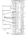
- the apparatus shown in Figures 1 -3 is an agri cultural machine, more specifically a soil cultivating machine for preparing a seed bed.
- the machine comprises a box-like frame portion 1 extending transversaly of the intended direction of operative travel A and extending at least substantially horizontal.
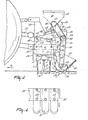
- each of the soil working members 3 includes a carrier 4 which extends at least substantially horizontally and is mounted on the lower end of a shaft 2, which end projects from the frame portion 1. At its ends, the carrier 4 accommodates a bushing 5, whose longitudinal centre line extends at least substantially parallel with the rotary axis of a soil working member 3. A fastening portion 6 of a tine 7 is disposed in each of the bushings 5.
- the portion 6 is fixed at the upper side by means of a nut 8 which can co-operate with screw-thread on the free end of the fastening portion, and at the bottom side by means of studs 9 relative to the bushing 5.
- the fastening portion 6 of the tine merges into a soil working portion 10, which is preferably blade-like.
- the working portion 10 of the tine has an at least substantially round cross-section which in the downward direction merges into a rectangular cross-section which, as is shown in the Figures 2 and 3, is in the form of a strip, via diametrically facing tapering parts 11.
- the downwardly tapering parts 11 reach to just above midway a working portion 10.
- the soil working portion 10 is bent rearwardly relative to the direction of rotation of a soil working member 3 in accordance with an at least substantially uniform curve (Figure 3).
- the portion 10 is furthermore twisted, in such a way that its leading side is located at a larger distance from the rotary axis of a soil working member 3 than its rear side.
- the ends of the box-like frame portion 1 are closed by plates 12 which extend upwardly and at least substantially parallel with the direction of operative travel A. The plates 12 reach to above the box-like frame portion and, at the leading side, are higher than at the rear side.
- each plate 12 is provided with a horizontal pin 13, which extends at least substantially transversely of the intended direction of operative travel A and about which an arm 14 which extends rearwardly along the inner side of the plate, is freely rotatable.
- the arms 14 are hingeably connected via pins 15, which extend _parallel to the pins 13, to an upwardly, preferably vertically, extending support 16.
- the longitudinal axes of the pins 13 and 15 constitute the pivots of a pivotal quadrangle 17.
- the foremost pivot points formed by the longitudinal centre lines of the pins 13 are separated from each other by a distance which is approximately half the distance between the pivot points constituted by the longitudinal centre lines of the pins 15 at the rear.
- the supports 16 are interconnected by means of a beam 18 which extends transversely of the direction of operative travel A and is located, when the arms 14 are in their lowest position, at the level of the box-like frame portion 1 (Figure 3).
- the beam 18 which extends at least substantially transversely of the direction of operative travel and at least substantially horizontally, is tube-like and preferably has a square cross-section.
- the beam 18 is arranged such that, considered from the bottom upwards, the upright edges are at a slight forward angle.
- the supports 16 are interconnected by means of a beam 19 ( Figure 2) which, as regards its construction, is similar to the beam 18 and extends parallel thereto.
- the supports 16 and the beam 19 constitute a supporting structure for a hopper 20, which extends transversely of the direction of operative travel A, that belongs to an apparatus 21 for applying fertilizer on or into the soil, e.g. artificial fertilizer.
- the bottom side of the hopper 20 includes a discharge mechanism, with the aid of which material can be fed from the hopper to discharging elements 22 which are contiguous to openings provided next to each other at the bottom side of the hopper.
- the discharge members in the form of pipes extend from the bottom of the hopper 20 through a portion 23 at an obliquely forward and downward angle, which portion merges at the level of, and somewhat above the box-like frame portion 1 via a curved portion into an at least substantially vertically arranged downwardly directed part 24, which extends to the upper side of the operative portion of the tines of the soil working members 3 ( Figures 2 and 3).
- the parts 24 are supported by a common support 25 at the front side of the box-like frame portion 1.
- a hopper 26 of a seed drill 27, which hopper extends transversely of the direction of operative travel A, is disposed just above the centre of and at the rear of the supports 16.
- the seed drill 27 is particularly suitable for grass seed.
- the hopper has a mechanism for feeding seed to a plurality of adjacent discharge members 28.
- the discharge members 28, constituted by pipes, extend from the bottom side of the hopper 26 through a portion 29 at a downward and forward angle and are folded over at the level of the box-like frame beam, merging into a part 30 which terminates at the level of the middle of the fastening portion 6 of the tines 7 of the soil working member 3 ( Figures 2 and 3).
- the part 30 tilts slightly forward.
- the discharge members 28 are supported by a common support 31 provided at the front side of the frame beam 18.
- the ends of the beam 18 are provided with plates 32 of a mainly triangular shape and whose upper side extends at a downward and rearward angle from the beam 18.
- a roller is arranged freely rotatably between the plates by means of shafts 33.
- the roller 34 includes a tubular portion 35 on which spaced-apart combs 36 formed by tines are arranged, the arrangement being such that the roller constitutes a packer roller.
- scraper elements 40 On the plate 38 are mounted by means of bolts 39 scraper elements 40, which extend downwardly and forwardly between the combs 36.
- the scraper elements 40 have concave upper sides and a rounded tip which bears against the tubular portion 35 in a point at a circumferential angle of approximately 45° from a horizontal plane through the rotary axis of the roller 34.
- a sprocket wheel 42 is fitted at one end of the roller 34 on a shaft 33 outside a plate 32 and . disposed inside a protecting cover 41.
- a chain 43 is passed round the sprocket wheel 42, which chain is also passed round a sprocket wheel 44 on a shaft 45 of the discharge mechanism of the seed drill 27.
- a second, identical sprocket wheel is provided on the shaft 45, round which sprocket wheel a chain 46 is passed, which is also passed round an identical sprocket wheel 47 on the shaft of the discharge mechanism at the bottom side of the hopper 20 of the fertilizer spreader 21.
- the chain 46 and the sprocket wheel 47 are contained within a protective cover 48.
- a straighttoothed pinion 48A is provided within the box-like frame portion 1 on the shaft 2 of each soil working member 3, in such a way that the pinions on the shafts of adjacent soil working members are in driven connection.
- the shaft of a soil working member 3 is extended and reaches into a gear box 49, in which the shaft is in driving connection via a speed variator 50 at the rear side, with a shaft which extends in the intended direction of operative travel A.
- the said shaft projects at the front side from the gear box 49 and can be connected to the power take-off shaft of a tractor via an intermediate shaft 51.
- the box-like frame portion 1 has a trestle 52 comprising a three-point hitch attachment for coupling to the three-point lifting hitch of a tractor.
- the machine described in the foregoing is particularly suitable for preparing a seed bed and subsequent sowing of grass seed.
- a working depth can be set with the aid of the roller 34 that the tines 7 cultivate a 3 -5 centimeters thick layer of soil.
- fertilizer can be fed from the hopper 20 of the fertilizer spreader 21 via the discharge members 22 in front of the soil working members 3, the fertilizer being intimately mixed with the soil by the tines 7.
- the grass seed is supplied in the region of the upper side of the roller 34 via the portions 30, the grass seed being brought, with a slight counter flow, directly into the earth which was previously displaced towards the roller 34 by the soil working members 3.
- roller 34 together with the fertilizer spreader 21 and the seed drill 27 can be adjusted in height relative to the box-like portion 1, it is achieved that the drive for the discharge mechanism of the fertilizer spreader and the seed drill, which is effected from the roller, can be maintained.
- the presence of the combs 36 promotes a continuous drive of the roller 34, whilst the tubular portion 35 ensures an appropriate compacting of the recently cultivated and sown earth.
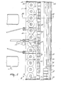
- Figures 5 -7 illustrate a second embodiment of a construction according to the invention. Components of the machine corresponding to those of the preceding embodiment have been given the same reference numerals.
- each soil working member 3 includes a blade-like tine 7A fitted in the same way as the tine 7 in the preceding embodiment, the upper side of the soil working portion also having an at least substantially round cross-section which, towards the free end, merges in the same manner into an at least substantially rectangular cross-section, all this such that also here the working portion of the tine is mainly blade-like.
- the soil working portion of the tine is straight and extends uniformly down whereby the longest side of the rectangle is located at feast substantially tangentially.
- the ends of the box-like frame 1 are closed by upwardly directed plates 55, which are located at least substantially parallel to the direction of operative travel A.
- each plate 55 has, above the upper side of the box-like frame portion 1, a pin 56 which extends transversely of the direction of operative travel A and about which one end of an arm 57 is freely rotatable. Behind the box-like frame portion, the arm 57 merges into a support 58 which extends downwardly and rearwardly.
- the roller 34 which also in this embodiment comprises scraper elements 40 of a construction identical to that of the preceding embodiment, is disposed capable of free rotation between the bottom sides of the supports 58.
- the beam 37 to which the scraper elements 40 are fitted is supported by plates 59 fitted to the rear of the supports 58 which extend at a downward and rearward angle.
- each support 58 is provided with strips 60 ( Figure 7) which extend at a rearward and upward angle and accommodate the hopper 26 of the grass seed drill 27.
- discharge members 61 are provided, which comprise a vertically downwardly extending portion 6a which ends before the roller 34 at the level of the bottom side of the tubular part 35 of this roller.
- the portions 62 of the discharge members 61 are supported by a common support 63 which, by means of arms 64, is mounted at the front of the support 58.
- the distance between the circumference of the roller 34 and the path described by the tines 7A is greater in this embodiment and is approximately five times the said distance in the first embodiment.
- a similar transmission as in the preceding embodiment is provided for driving the discharge mechanism of the seed drill 27.
- the arms 57 are adjustable in height with the aid of a known adjusting means 57A and consequently also the roller 34 for setting the working depth of the tines 7A.
- the mode of operation of the machine in accordance with the second embodiment substantially corresponds to the mode of operation of the first embodiment of the machine; however, now no fertilizer is fed in front of the soil working members, whereas the grass seed is discharged near the bottom side of the roller 34 into the rearwardly displaced earth. Discharging the grass seed from a low position may result in a reduced spread, so that optionally a greater density of the spread pattern can be obtained, whilst, in addition, the risk of the grass seed being dispersed by the wind is reduced.
- the seed drill 27 can be adjusted in height together with the roller 34.
- a tandem system of two rollers 34 is substituted for one roller, these rollers being so arranged relative to each other that the combs 36 on one roller move between the combs 36 on the other roller.
- Driving of the discharge mechanism of the seed drill 27 is effected in this embodiment from a sprocket 65 on a shaft 33 of the foremost roller 34 via a chain 66 and two adjacent sprockets 67 provided on a shaft 68 disposed between the rollers 34.
- a chain 69 is passed round the outermost sprocket 67 and also around the sprocket 44 on the shaft of the discharge mechanism of the seed drill 27.
- the working depth of the blade-like tines 7A can be set with the aid of the rollers 34 and this working depth is preferably such that the tines leave a cultivated layer of soil of 3 -5 centimeters thick.
- the seed drill 27 can be adjusted, together with the rollers 34, in the vertical direction relative to the box-like frame portion 1, whereby the drive for the discharge mechanism of the seed drill 27 is maintained.
- the round-tipped scraper members 40 it is achieved that the earth is removed very gradually from the tubular portion 35 of the roller 34, thus preventing the forming of clods.
- the rearmost roller may comprise scraper members 40. Furthermore, the combs of the last roller effect scraping of the earth of the first roller. Clogging can be easily obviated by means of the rounded tips of the scraper elements 40.
- the tines as used in the first embodiment are very suitable for use in heavy soils.
Landscapes
- Life Sciences & Earth Sciences (AREA)
- Engineering & Computer Science (AREA)
- Mechanical Engineering (AREA)
- Soil Sciences (AREA)
- Environmental Sciences (AREA)
- Soil Working Implements (AREA)
Applications Claiming Priority (4)
| Application Number | Priority Date | Filing Date | Title |
|---|---|---|---|
| NL8501285 | 1985-05-07 | ||
| NL8501286 | 1985-05-07 | ||
| NL8501286A NL8501286A (nl) | 1985-05-07 | 1985-05-07 | Grondbewerkingsmachine. |
| NL8501285A NL8501285A (nl) | 1985-05-07 | 1985-05-07 | Grondbewerkingsmachine. |
Publications (3)
| Publication Number | Publication Date |
|---|---|
| EP0201135A2 true EP0201135A2 (de) | 1986-11-12 |
| EP0201135A3 EP0201135A3 (en) | 1987-10-21 |
| EP0201135B1 EP0201135B1 (de) | 1995-03-08 |
Family
ID=26646044
Family Applications (1)
| Application Number | Title | Priority Date | Filing Date |
|---|---|---|---|
| EP19860200780 Expired - Lifetime EP0201135B1 (de) | 1985-05-07 | 1986-05-05 | Bodenbearbeitungsmaschine |
Country Status (3)
| Country | Link |
|---|---|
| EP (1) | EP0201135B1 (de) |
| AU (1) | AU588590B2 (de) |
| DE (1) | DE3650254T2 (de) |
Cited By (2)
| Publication number | Priority date | Publication date | Assignee | Title |
|---|---|---|---|---|
| EP0327869A1 (de) * | 1988-02-08 | 1989-08-16 | Amazonen-Werke H. Dreyer GmbH & Co. KG | Geschlossene Bestellkombination |
| FR2951901A1 (fr) * | 2009-11-04 | 2011-05-06 | Alois Pottinger Maschinenfabrik Gmbh | Machine de travail du sol |
Citations (13)
| Publication number | Priority date | Publication date | Assignee | Title |
|---|---|---|---|---|
| US1916330A (en) * | 1932-05-19 | 1933-07-04 | Nordstrom Abel | Roller for crushing clods |
| US2667362A (en) * | 1951-09-20 | 1954-01-26 | Leslie R Woodward | Corn planter packer wheel scraper |
| NL7200225A (de) * | 1972-01-07 | 1973-07-10 | ||
| FR2284264A1 (fr) * | 1974-09-14 | 1976-04-09 | Amazonen Werke Dreyer H | Combinaison d'instruments pour semer des graminees |
| DE2462240A1 (de) * | 1974-08-09 | 1976-06-24 | Amazonen Werke Dreyer H | Packerwalze |
| FR2342015A1 (fr) * | 1976-02-25 | 1977-09-23 | Lely Nv C Van Der | Machine pour travailler le sol |
| DE2738211A1 (de) * | 1976-08-30 | 1978-03-09 | Lely Nv C Van Der | Bodenbearbeitungsgeraet mit einem zusatzgeraet |
| AT342906B (de) * | 1976-04-09 | 1978-04-25 | Prillinger Karl | Bodenbearbeitungsgerat |
| US4088083A (en) * | 1976-11-05 | 1978-05-09 | C. Van Der Lely N.V. | Rotary harrow and attachments |
| FR2414856A1 (fr) * | 1978-01-23 | 1979-08-17 | Niemeyer Gmbh & Co Kg Soehne | Machine pour la culture du sol et pour les semailles |
| FR2499817A1 (fr) * | 1981-02-17 | 1982-08-20 | Amazonen Werke Dreyer H | Semoir mecanique attelable a un tracteur |
| GB2139462A (en) * | 1981-01-13 | 1984-11-14 | Lely Nv C Van Der | Soil cultivating implements |
| US4509438A (en) * | 1982-08-31 | 1985-04-09 | Maschinenwerk Rau Gmbh | Combination implement for agricultural cultivation |
-
1986
- 1986-05-02 AU AU57039/86A patent/AU588590B2/en not_active Ceased
- 1986-05-05 EP EP19860200780 patent/EP0201135B1/de not_active Expired - Lifetime
- 1986-05-05 DE DE19863650254 patent/DE3650254T2/de not_active Expired - Fee Related
Patent Citations (13)
| Publication number | Priority date | Publication date | Assignee | Title |
|---|---|---|---|---|
| US1916330A (en) * | 1932-05-19 | 1933-07-04 | Nordstrom Abel | Roller for crushing clods |
| US2667362A (en) * | 1951-09-20 | 1954-01-26 | Leslie R Woodward | Corn planter packer wheel scraper |
| NL7200225A (de) * | 1972-01-07 | 1973-07-10 | ||
| DE2462240A1 (de) * | 1974-08-09 | 1976-06-24 | Amazonen Werke Dreyer H | Packerwalze |
| FR2284264A1 (fr) * | 1974-09-14 | 1976-04-09 | Amazonen Werke Dreyer H | Combinaison d'instruments pour semer des graminees |
| FR2342015A1 (fr) * | 1976-02-25 | 1977-09-23 | Lely Nv C Van Der | Machine pour travailler le sol |
| AT342906B (de) * | 1976-04-09 | 1978-04-25 | Prillinger Karl | Bodenbearbeitungsgerat |
| DE2738211A1 (de) * | 1976-08-30 | 1978-03-09 | Lely Nv C Van Der | Bodenbearbeitungsgeraet mit einem zusatzgeraet |
| US4088083A (en) * | 1976-11-05 | 1978-05-09 | C. Van Der Lely N.V. | Rotary harrow and attachments |
| FR2414856A1 (fr) * | 1978-01-23 | 1979-08-17 | Niemeyer Gmbh & Co Kg Soehne | Machine pour la culture du sol et pour les semailles |
| GB2139462A (en) * | 1981-01-13 | 1984-11-14 | Lely Nv C Van Der | Soil cultivating implements |
| FR2499817A1 (fr) * | 1981-02-17 | 1982-08-20 | Amazonen Werke Dreyer H | Semoir mecanique attelable a un tracteur |
| US4509438A (en) * | 1982-08-31 | 1985-04-09 | Maschinenwerk Rau Gmbh | Combination implement for agricultural cultivation |
Cited By (2)
| Publication number | Priority date | Publication date | Assignee | Title |
|---|---|---|---|---|
| EP0327869A1 (de) * | 1988-02-08 | 1989-08-16 | Amazonen-Werke H. Dreyer GmbH & Co. KG | Geschlossene Bestellkombination |
| FR2951901A1 (fr) * | 2009-11-04 | 2011-05-06 | Alois Pottinger Maschinenfabrik Gmbh | Machine de travail du sol |
Also Published As
| Publication number | Publication date |
|---|---|
| EP0201135A3 (en) | 1987-10-21 |
| DE3650254D1 (de) | 1995-04-13 |
| EP0201135B1 (de) | 1995-03-08 |
| AU5703986A (en) | 1986-11-13 |
| AU588590B2 (en) | 1989-09-21 |
| DE3650254T2 (de) | 1996-08-01 |
Similar Documents
| Publication | Publication Date | Title |
|---|---|---|
| US4088083A (en) | Rotary harrow and attachments | |
| US3810434A (en) | Agricultural cultivator and seed frill combinations | |
| US4241674A (en) | Sub-soil planter | |
| US4762075A (en) | Seed/fertilizer minimum tillage planter | |
| US4361191A (en) | Seedbed preparation implement | |
| US4036154A (en) | Soil cultivating implements | |
| US4324295A (en) | Agricultural implement attachable to a tractor | |
| US4034687A (en) | Cultivators | |
| US4155315A (en) | Mobile spreader | |
| US3995570A (en) | Cultivators | |
| CZ115498A3 (cs) | Integrované zařízení pro kultivaci půdy | |
| US3899029A (en) | Rotary harrows | |
| US4058068A (en) | Soil cultivating and sowing implement | |
| US5361712A (en) | Cultivating apparatus for leveling, cultivating, and resowing lawns or fields | |
| GB1559887A (en) | Machine for depositing seeds and fertiliser in the ground | |
| EP0337534B1 (de) | Bodenbearbeitungsmaschine | |
| EP0506210B1 (de) | Streuer | |
| EP0201135A2 (de) | Bodenbearbeitungsmaschine | |
| US4127074A (en) | Soil cultivating implement | |
| EP0150080A2 (de) | Bodenbearbeitungsgeräte | |
| EP0616757A2 (de) | Bodenbearbeitungsmaschine | |
| US4057110A (en) | Rotary harrows | |
| US3664279A (en) | Earth working and planting apparatus and method of planting seed | |
| US4147117A (en) | Cultivating implements | |
| EP0305601B1 (de) | Gerät zur Bodenbearbeitung |
Legal Events
| Date | Code | Title | Description |
|---|---|---|---|
| PUAI | Public reference made under article 153(3) epc to a published international application that has entered the european phase |
Free format text: ORIGINAL CODE: 0009012 |
|
| AK | Designated contracting states |
Kind code of ref document: A2 Designated state(s): DE FR GB NL |
|
| PUAB | Information related to the publication of an a document modified or deleted |
Free format text: ORIGINAL CODE: 0009199EPPU |
|
| RA1 | Application published (corrected) |
Date of ref document: 19861217 Kind code of ref document: A2 |
|
| PUAL | Search report despatched |
Free format text: ORIGINAL CODE: 0009013 |
|
| AK | Designated contracting states |
Kind code of ref document: A3 Designated state(s): DE FR GB NL |
|
| 17P | Request for examination filed |
Effective date: 19880411 |
|
| 17Q | First examination report despatched |
Effective date: 19890125 |
|
| GRAA | (expected) grant |
Free format text: ORIGINAL CODE: 0009210 |
|
| AK | Designated contracting states |
Kind code of ref document: B1 Designated state(s): DE FR GB NL |
|
| PG25 | Lapsed in a contracting state [announced via postgrant information from national office to epo] |
Ref country code: FR Effective date: 19950308 |
|
| REF | Corresponds to: |
Ref document number: 3650254 Country of ref document: DE Date of ref document: 19950413 |
|
| PG25 | Lapsed in a contracting state [announced via postgrant information from national office to epo] |
Ref country code: GB Effective date: 19950608 |
|
| EN | Fr: translation not filed | ||
| PLBE | No opposition filed within time limit |
Free format text: ORIGINAL CODE: 0009261 |
|
| STAA | Information on the status of an ep patent application or granted ep patent |
Free format text: STATUS: NO OPPOSITION FILED WITHIN TIME LIMIT |
|
| GBPC | Gb: european patent ceased through non-payment of renewal fee |
Effective date: 19950608 |
|
| 26N | No opposition filed | ||
| PGFP | Annual fee paid to national office [announced via postgrant information from national office to epo] |
Ref country code: NL Payment date: 20020418 Year of fee payment: 17 |
|
| PGFP | Annual fee paid to national office [announced via postgrant information from national office to epo] |
Ref country code: DE Payment date: 20020520 Year of fee payment: 17 |
|
| PG25 | Lapsed in a contracting state [announced via postgrant information from national office to epo] |
Ref country code: NL Free format text: LAPSE BECAUSE OF NON-PAYMENT OF DUE FEES Effective date: 20031201 |
|
| PG25 | Lapsed in a contracting state [announced via postgrant information from national office to epo] |
Ref country code: DE Free format text: LAPSE BECAUSE OF NON-PAYMENT OF DUE FEES Effective date: 20031202 |
|
| NLV4 | Nl: lapsed or anulled due to non-payment of the annual fee |
Effective date: 20031201 |