EP0200595A2 - Dispositif de chauffage - Google Patents
Dispositif de chauffage Download PDFInfo
- Publication number
- EP0200595A2 EP0200595A2 EP86400646A EP86400646A EP0200595A2 EP 0200595 A2 EP0200595 A2 EP 0200595A2 EP 86400646 A EP86400646 A EP 86400646A EP 86400646 A EP86400646 A EP 86400646A EP 0200595 A2 EP0200595 A2 EP 0200595A2
- Authority
- EP
- European Patent Office
- Prior art keywords
- fire
- allowing
- hearth
- wood
- combustion
- Prior art date
- Legal status (The legal status is an assumption and is not a legal conclusion. Google has not performed a legal analysis and makes no representation as to the accuracy of the status listed.)
- Granted
Links
Images

Classifications
-
- F—MECHANICAL ENGINEERING; LIGHTING; HEATING; WEAPONS; BLASTING
- F24—HEATING; RANGES; VENTILATING
- F24B—DOMESTIC STOVES OR RANGES FOR SOLID FUELS; IMPLEMENTS FOR USE IN CONNECTION WITH STOVES OR RANGES
- F24B1/00—Stoves or ranges
- F24B1/18—Stoves with open fires, e.g. fireplaces
- F24B1/191—Component parts; Accessories
- F24B1/195—Fireboxes; Frames; Hoods; Heat reflectors
- F24B1/1952—Multiple fire-boxes
-
- F—MECHANICAL ENGINEERING; LIGHTING; HEATING; WEAPONS; BLASTING
- F24—HEATING; RANGES; VENTILATING
- F24B—DOMESTIC STOVES OR RANGES FOR SOLID FUELS; IMPLEMENTS FOR USE IN CONNECTION WITH STOVES OR RANGES
- F24B1/00—Stoves or ranges
- F24B1/18—Stoves with open fires, e.g. fireplaces
- F24B1/185—Stoves with open fires, e.g. fireplaces with air-handling means, heat exchange means, or additional provisions for convection heating ; Controlling combustion
- F24B1/188—Stoves with open fires, e.g. fireplaces with air-handling means, heat exchange means, or additional provisions for convection heating ; Controlling combustion characterised by use of heat exchange means , e.g. using a particular heat exchange medium, e.g. oil, gas
- F24B1/1885—Stoves with open fires, e.g. fireplaces with air-handling means, heat exchange means, or additional provisions for convection heating ; Controlling combustion characterised by use of heat exchange means , e.g. using a particular heat exchange medium, e.g. oil, gas the heat exchange medium being air only
-
- F—MECHANICAL ENGINEERING; LIGHTING; HEATING; WEAPONS; BLASTING
- F24—HEATING; RANGES; VENTILATING
- F24B—DOMESTIC STOVES OR RANGES FOR SOLID FUELS; IMPLEMENTS FOR USE IN CONNECTION WITH STOVES OR RANGES
- F24B13/00—Details solely applicable to stoves or ranges burning solid fuels
- F24B13/02—Arrangement or mountings of fire-grate assemblies; Arrangement or mountings of linings for fire-boxes, e.g. fire-backs
Definitions
- the invention relates to an energy-saving heat recuperator provided with a brazier-hearth sealed storage store whose inclinations make it possible to recover the embers and a maximum of energy produced by them.
- a double chimney flue provided with a special drain with two outlets, one of which is provided with a closing hatch, allows operation with decorative open fire or continuous fire.
- recuperator makes it possible to recover the heat by the radiation of normal and decorative wood fire, by embers and by gases in rising combustion. It is installed in a traditional decorative fireplace. It is used for individuals, small and medium industry. It is constituted by a triple hearth with triple combustion, normal decorative fire on chenets, fire by embers falling in the brazier - combustion chamber which recovers in rising combustion, fire by combustion chamber wood, coal, gas, fuel.
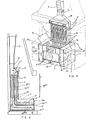
- FIG. 1 shows the sectional view of the exchanger (1) for the production of hot water, or mixed hot water - hot air (fig. 3).
- the exchanger (1 and 1a - fig. 1 - 3 - 5 and 6) is inside the combustion chamber (3).
- the brazier-hearth (2) is a store for storing embers and wood or charcoal at continuous fire. On the top of the brazier-foyer storage store (2) the fire is normal decorative on crawlers and recovers by radiation. As the wood burns, the embers descend into the brazier-hearth warehouse (2) towards the grate (17) at this time the combustion is rising.
- the placement of secondary ventilations (6ter) allows horizontal combustion, the position of the exchanger (17bis) retaining the wood allows reverse and horizontal combustion. So three combustions at a time. All energies are recovered. Secondary air arrives through the inlet (6bis) or through the rear. A fan controlled by a room thermostat or an aquastat can be placed at this entry (6bis) to pulsate the secondary air, which avoids the risks of
- an oil or gas burner can be placed in the combustion chamber (3bis).
- the doors (14 fig. 1 and 5) can be replaced by a sliding plate for adjusting the primary air flow rate of the perforated angle (47).
- a grid (17 ter) slightly inclined can be placed to retain the embers and allows the evacuation of the ashes towards the grid (17).
- FIG. 2 represents an interior and exterior view of the brazier-foyer storage store (2), there is the drawer (7) with the primary or secondary air supply (6) for rising light.
- the inclinations of the walls of this brazier-hearth warehouse store (2) allow the oven (32), the loading door with continuous fire (28) allows the loading of wood or coal, the grid (17), the arrivals of secondary air (6ter) and a perforated angle iron (47) for primary air intake for horizontal and inverted fire.
- the casing (48) of the brazier-hearth store storage (2) allows the interlocking of the exchanger (1 and lbis) and its envelope (19 fig. 3 - 5 and 9) which is closed by a trap door for cleaning (19bis - fig 6).
- FIG 3 shows the exchangers (1 and lbis) which are closed by a removable tip (21) for cleaning the smoke outlets (34).
- the exchangers (1 and lbis) are provided with a non-figured inlet of fresh air or pulsed by a fan, this air exits through the outlet (22) which can be double.
- FIG. 4 represents a drain (44) with two smoke outlets, the outlet (49) for the normal decorative fire, the outlet (50) for the continuous wood, coal, fuel or gas fire.
- a hatch (43) can close the outlet (49).
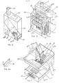
- Figure 5 shows the barbecue, stove and rotisserie assembly.
- Two lateral cabinets (33) on each lateral side of the furnace and the brazier serve as housing for pumps, manometers, batteries, flexon, etc ... or possibly flat heaters. They are not compulsory o They can, if necessary, be incorporated into the decorative fireplace.
- tubular exchangers (1 and 1a) as well as the tubulars (17a) placed inside this decorative fireplace or stove recover and allow to heat a restaurant, a hotel and one or more hot water tanks and tanks of storage.
- FIG. 6 represents the brazier-hearth storage warehouse (2) which is hollow under the exchangers (1 and 1a) each of these exchangers being made up of tubular elements. It has sealed doors ( 14 - fig 5) for continuous fire operation either wood or charcoal, these doors can be replaced by a sliding plate for adjusting the air flow primary of the perforated angle (47).
- the interior of the brazier-foyer storage store (2) can be provided with tubulars (17 bis) with water circulation connected by the inlets and outlets (11) to the tubular exchangers (1 and 1a), the grid (17 ) retains the embers under the tubulars (17bis).
- a watertight door (28) can be fitted on the front of the brazier-fireplace storage store (2) to allow the loading of wood, coal or the installation of a combustion burner l i qu i - de and access for cleaning.
- the tubulars (17 bis) will be placed in the upper part of the brazier, the doors (14) and the grid (17) will be removed and the brazier-foyer storage store (2) in refractory steel will be fully. closed and waterproof.
- the exchanger hatch (4) will be closed and the gases and fumes will pass through the second duct (5).
- FIG. 7 represents the exploded view of the brazier-hearth storage store (2) for an automatic charcoal fire which is hollow under the exchangers (1 fig. 9) for the production of hot water and (lbis fig 9) for the hot air production.
- the brazier-hearth store store (2) has a double hearth inside, one for wood combustion, it has a grate (17) which retains the embers, the other for coal combustion with a inclined grid (37) which acts as a burner
- a zipper movable in all directions (37 bis) is used for cleaning the two fireplaces and provides the primary air which penetrates through the adjustable hatch (6) of the drawer (7) under the wood fireplace . Secondary air arrives through the inlets (6bis) and leaves through the outlets (6ter).
- a motor pulses the primary air through the inlet (6quat.) Under the grid (37).
- the brazier-hearth is composed of a ramp (39) for the automatic lowering of the coal, the second distribution adjustment is made by a manual shutter (36) and separates the two wood and coal hearths.
- Figure 8 shows the coal tank which is incorporated in the chimney and is not visible outside, it is provided with an inlet (40) for receiving the coal, it can be above, on the sides or behind. Inside there can be two inclinations (45) which make it possible to direct the charcoal towards a central hearth or towards two hearths by the exits (42 bis).
- a manual shutter (42) actuated by a lever (41) makes it possible to regulate the automatic arrival of the coal.
- FIG. 9 shows the exploded view of the entire recuperator, both with water and with hot air.
- the gases and smoke pass through the conduits (34) and go towards the outlet (5).
- the conduits (34) are located in a sealed envelope (19) provided with grids (33) which retain the heat by braking the push of air which is thus further heated and is sent to the outlets (22).
- the gases and smoke from the water recuperator pass through the conduit (3) and go towards the outlet (5).
- Figure 10 shows in detail the manual shutter (36) of the second setting of the arrival of coal.
Landscapes
- Engineering & Computer Science (AREA)
- Chemical & Material Sciences (AREA)
- Combustion & Propulsion (AREA)
- Mechanical Engineering (AREA)
- General Engineering & Computer Science (AREA)
- Solid-Fuel Combustion (AREA)
Abstract
Description
- L'invention concerne un récupérateur de chaleur économiseur d'énergie muni d'un brasier-foyer magasin de stokage étanche dont les inclinaisons permettent de récupérer les braises et un maximum d'énergie produitent par celles-ci. Un double conduit de cheminée muni d'un avaloir spécial à deux sorties dont l'une d'elles est munie d'une trappe de fermeture permet le fonctionnement à feu ouvert décoratif ou à feu continu.
- Les avantages du récupérateur sont multiples, il permet de récupérer la chaleur par le rayonnement du feu normal et décoratif bois, par les braises et par les gaz en combustion montante. Il s'installe dans une cheminée traditionnelle décorative. Il sert aux particuliers, à la petite et moyenne industrie. Il est constitué par un triple foyer à triple combustion, feu décoratif normal sur chenêts, feu par les braises tombant dans le brasier- chambre de combustion qui récupère en combustion montante, feu par chambre de combustion bois, charbon, gaz, fuel.
- La figure 1 représente la vue en coupe de l'échangeur (1) pour la production d'eau chaude, ou mixte eau chaude - air chaud (fig. 3). L'échangeur (1 et 1 bis - fig. 1 - 3 - 5 et 6) est à l'intérieur de la chambre de combustion (3). Le brasier-foyer (2) est un magasin de stokage des braises et du bois ou du charbon à feu continu. Sur le dessus du brasier-foyer magasin de stokage (2) le feu est décoratif normal sur chenets et récupère par rayonnement. Au fur et à mesure de la combustion du bois les braises descendent dans le brasier-foyer magasin de stokage (2) vers la grille (17) à ce moment la combustion est montante. Le placement des ventilations secondaires (6ter) permet la combustion horizontale, la position de l'échangeur (17bis) retenant le bois permet la combustion inversée et horizontale. Donc trois combustions à la fois. Toutes les énergies sont récupérées. L'air secondaire arrive par l'entrée (6bis) ou par la partie arrière. Un ventilateur controlé par un thermostat d'ambiance ou un aquastat peut être placé à cette entrée (6bis) pour pulser l'air secondaire, ce qui évite les risques de surchauffe.
- Dans la chambre de combustion (3bis) un bruleur à mazout ou à gaz peut être placé. Les portes (14 fig. 1 et 5) peuvent être remplacées par une plaque coulissante pour réglage du débit de l'air primaire de la cornière perforée (47).
- Pour les barbecues ou rotissoires une grille (17 ter) légèrement inclinée peut être placée afin de retenir les braises et permet l'évacuation des cendres vers la grille (17).
- La figure 2 représente une vue intérieure et extérieure du brasier-foyer magasin de stokage (2) on y remarque le tiroir (7) avec l'arrivée d'air primaire ou secondaire (6) pour feu montant. Les inclinaisons des parois de ce brasier-foyer magasin de stokage (2) permettent le four (32), la porte de chargement à feu continu (28) permet le chargement du bois ou du charbon, la grille (17), les arrivées d'air secondaire (6ter) et une cornière perforée (47) pour arrivée d'air primaire pour feu horizontal et inversé. Le caisson (48) du brasier-foyer magasin de stokage (2) permet l'emboitement de l'échangeur (1 et lbis) et de son enveloppe (19 fig. 3 - 5 et 9) qui est fermé par unetrappe de visite pour nettoyage (19bis - fig 6).
- La figure 3 représente les échangeurs (1 et lbis) qui sont fermés par un embout (21) démontable pour le nettoyage des sorties des fumées (34). Les échangeurs (1 et lbis) sont munis d'une entrée non figurée d'air frais ou pulsé par un ventilateur, cet air sort par la sortie (22) qui peut être double.
- La figure 4 représente un avaloir (44) avec deux sorties de fumée, la sortie (49) pour le feu décoratif normal, la sortie (50) pour le feu continu bois, charbon, fuel ou gaz. Une trappe (43) peut fermer la sortie (49).
- La figure 5 représente l'ensemble barbecue, cuisinière et rotis- soire. Deux armoires latérales (33) de chaque coté latéral du four et du brasier servent de logement aux pompes, manomètres, batteries, flexon, etc... ou éventuellement de chauffe plats. Elles ne sont pas obligatoireso Elles peuvent être, éventuellement, incorporées dans la cheminée décorative.
- Les échangeurs tubulaires (1 et 1 bis) ainsi que.les tubulaires (17 bis) placés à l'intérieur de cette cheminée décorative ou cuisinière récupèrent et permettent de chauffer un restaurant, un hotel et un ou plusieurs ballons d'eau chaude et ballons de stokage.
- La disposition sur la figure 6 en coupe représente le brasier-foyer magasin de stokage (2) qui est en creux sous les échangeurs (1 et 1 bis) chacun de ces échangeurs étant composé d'éléments tubu- laireso Il comporte des portes étanches (14 - fig 5) pour fonctionnement à feu continu soit bois soit charbon, ces portes peuvent être remplacées par une plaque coulissante pour réglage du débit de l'air primaire de la cornière perforée (47). L'intérieur du brasier-foyer magasin de stokage (2) peut être muni de tubulaires (17 bis) à circulation d'eau reliés par les entrées et sorties (11) aux échangeurs tubulaires (1 et 1 bis), la grille (17) retient les braises sous les tubulaires (17bis). Une porte étanche (28) peut être aménagée sur le devant du brasier-foyer magasin de stokage (2) pour permettre le chargement du bois, du charbon ou la pose d'un bruleur à combustion liqui- de et l'accès pour son nettoyage. Dans le cas de la pose d'un bruleur, les tubulaires (17 bis) seront placés en partie haute du brasier, les portes (14) et la grille (17) seront supprimées et le brasier-foyer magasin de stokage (2) en acier réfractaire sera entièrement . fermé et étanche. La trappe échangeur (4) sera fermée et les gaz et fumées emprunteront le deuxième conduit (5).
- La figure 7 représente la vue éclatée du brasier-foyer magasin de stokage (2) pour feu à charbon automatique qui est en creux sous les échangeurs (1 fig. 9) pour la production d'eau chaude et (lbis fig 9) pour la production d'air chaud. Le brasier-foyer magasin de stokage (2) est à double foyer à l'intérieur, l'un pour la combustion au bois, il comporte une grille (17) qui retient les braises, l'autre pour la combustion au charbon avec une grille inclinée (37) qui fait office de bruleuro Une tirette mobile en tous sens (37 bis) sert au nettoyage des deux foyers et apporte l'air primaire qui penètre par la trappe règlable(6) du tiroir (7) sous le foyer bois. L'air secondaire arrive par les entrées (6bis) et s'en va par les sorties (6ter).
- Pour le fonctiornement au charbon un moteur pulse l'air primaire par l'entrée (6quat.) sous la grille (37).
- Le brasier-foyer est composé d'une rampe (39) pour la descente automatique du charbon, le deuxième réglage de distribution se fait par un volet manuel (36) et sépare les deux foyers bois et charbon.
- La figure 8 représente le réservoir à charbon qui est incorporé dans la cheminée et n'est pas visible à l'extérieur, il est muni d'une entrée (40) pour réception du charbon, elle peut se trouver au-dessus, sur lescotés ou derrière. A l'intérieur il peut y avoir deux inclinaisons (45) qui permettent de diriger le charbon vers un foyer central ou vers deux foyers par les sorties (42 bis). Un volet manuel (42) actionné par une manette (41) permet de régler l'arrivée automatique du charbon.
- La figure 9 représente la vue éclatée de l'ensemble du récuoé- rateur, tant à eau qu'à air chaud. Pour l'air chaud les gaz et fumée passent par les conduits (34) et vont vers la sortie (5). Les conduits (34) se trouvent dans une enveloppes étanche (19) muni de grilles (33) qui retiennent la chaleur en freinant la poussée d'air qui est ainsi davantage réchauffé et est envoyé vers les sorties (22). Les gaz et fumée du récupérateur à eau passe par le conduit (3) et vont vers la sortie (5).
- La figure 10 représente en détail le volet manuel (36) du deuxième réglage de l'arrivée du charbon.
Claims (9)
Applications Claiming Priority (6)
| Application Number | Priority Date | Filing Date | Title |
|---|---|---|---|
| FR8504578A FR2579726B2 (fr) | 1985-03-27 | 1985-03-27 | Recuperateur de chaleur pour economiser l'energie |
| FR8504578 | 1985-03-27 | ||
| FR8512105 | 1985-08-07 | ||
| FR8512105A FR2586088B2 (fr) | 1985-08-07 | 1985-08-07 | Recuperateur de chaleur pour economiser l'energie |
| FR8603953 | 1986-03-19 | ||
| FR8603953A FR2596142B2 (fr) | 1986-03-19 | 1986-03-19 | Recuperateur de chaleur pour economiser l'energie |
Publications (3)
| Publication Number | Publication Date |
|---|---|
| EP0200595A2 true EP0200595A2 (fr) | 1986-11-05 |
| EP0200595A3 EP0200595A3 (en) | 1987-03-04 |
| EP0200595B1 EP0200595B1 (fr) | 1992-03-18 |
Family
ID=27251270
Family Applications (1)
| Application Number | Title | Priority Date | Filing Date |
|---|---|---|---|
| EP19860400646 Expired - Lifetime EP0200595B1 (fr) | 1985-03-27 | 1986-03-26 | Dispositif de chauffage |
Country Status (2)
| Country | Link |
|---|---|
| EP (1) | EP0200595B1 (fr) |
| DE (1) | DE3684356D1 (fr) |
Cited By (5)
| Publication number | Priority date | Publication date | Assignee | Title |
|---|---|---|---|---|
| EP0867662A1 (fr) * | 1997-03-27 | 1998-09-30 | CDK International | Dispositif de réglage de la combustion dans une cheminée à double foyer |
| FR2764971A1 (fr) * | 1997-06-18 | 1998-12-24 | Cheminees Seguin Duteriez Sa | Dispositif domestique de combustion combinant foyer ouvert et foyer ferme |
| EP1344979A1 (fr) * | 2002-03-15 | 2003-09-17 | Rüegg Cheminée AG | Cuisinière |
| FR2923288A1 (fr) * | 2007-11-05 | 2009-05-08 | David Lachaize | Dispositif de combustion comportant un foyer superieur et un foyer inferieur,la paroi superieure du foyer inferieur, divisee en deux volets pivotants, formant une sole pour le foyer superieur. |
| FR3012576A1 (fr) * | 2013-10-31 | 2015-05-01 | Jean-Michel Delage | Dispositif de chauffage de type chaudiere et procede de fonctionnement |
Families Citing this family (1)
| Publication number | Priority date | Publication date | Assignee | Title |
|---|---|---|---|---|
| CN104315545A (zh) * | 2014-11-03 | 2015-01-28 | 昆山富凌能源利用有限公司 | 多用途节能灶 |
Family Cites Families (7)
| Publication number | Priority date | Publication date | Assignee | Title |
|---|---|---|---|---|
| GB280035A (en) * | 1926-11-15 | 1927-11-10 | Karl Mellor Gibbons | Improvements in household ranges |
| GB331943A (en) * | 1929-04-19 | 1930-07-17 | John Warr | Improved method of and means for preventing or diminishing the formation of smoke in the burning of coal in open fireplaces |
| GB366156A (en) * | 1930-01-14 | 1932-02-04 | William Cheyne | Improvements in fire grates |
| FR2471553A1 (fr) * | 1979-12-10 | 1981-06-19 | Mollard Pierre | Capteur de chaleur pouvant etre installe notamment dans une cheminee domestique et procede pour porter a une temperature plus elevee un fluide tel que de l'eau |
| FR2475696A1 (fr) * | 1980-02-13 | 1981-08-14 | Manteau Jean Louis | Chaudiere d'atre |
| DE3126186A1 (de) * | 1980-07-04 | 1982-05-06 | Urban 1040 Wien Egger | "offener kamin zur verfeuerung insbesondere von festem, aber auch gasfoermigem oder fluessigem brennstoff" |
| FR2541429B1 (fr) * | 1983-02-17 | 1986-11-21 | Graziani Adelciso | Recuperateur de chaleur pour economiser l'energie |
-
1986
- 1986-03-26 DE DE8686400646T patent/DE3684356D1/de not_active Expired - Lifetime
- 1986-03-26 EP EP19860400646 patent/EP0200595B1/fr not_active Expired - Lifetime
Cited By (6)
| Publication number | Priority date | Publication date | Assignee | Title |
|---|---|---|---|---|
| EP0867662A1 (fr) * | 1997-03-27 | 1998-09-30 | CDK International | Dispositif de réglage de la combustion dans une cheminée à double foyer |
| FR2761460A1 (fr) * | 1997-03-27 | 1998-10-02 | Cdk International | Dispositif de reglage de la combustion dans une cheminee a double foyer |
| FR2764971A1 (fr) * | 1997-06-18 | 1998-12-24 | Cheminees Seguin Duteriez Sa | Dispositif domestique de combustion combinant foyer ouvert et foyer ferme |
| EP1344979A1 (fr) * | 2002-03-15 | 2003-09-17 | Rüegg Cheminée AG | Cuisinière |
| FR2923288A1 (fr) * | 2007-11-05 | 2009-05-08 | David Lachaize | Dispositif de combustion comportant un foyer superieur et un foyer inferieur,la paroi superieure du foyer inferieur, divisee en deux volets pivotants, formant une sole pour le foyer superieur. |
| FR3012576A1 (fr) * | 2013-10-31 | 2015-05-01 | Jean-Michel Delage | Dispositif de chauffage de type chaudiere et procede de fonctionnement |
Also Published As
| Publication number | Publication date |
|---|---|
| EP0200595B1 (fr) | 1992-03-18 |
| EP0200595A3 (en) | 1987-03-04 |
| DE3684356D1 (de) | 1992-04-23 |
Similar Documents
| Publication | Publication Date | Title |
|---|---|---|
| US4068650A (en) | Fireplace heating channel | |
| US4088113A (en) | Wood burning automatic swimming pool heater | |
| CN104236076A (zh) | 一种电气化采暖炉 | |
| US4254756A (en) | Fireplace apparatus | |
| EP0200595B1 (fr) | Dispositif de chauffage | |
| US4368721A (en) | Woodburning stove | |
| US3934554A (en) | Water and room heater | |
| GB2100419A (en) | A stove | |
| RU2087806C1 (ru) | Печь для бань | |
| FR2473157A1 (fr) | Cheminee a foyer ouvert et foyer ferme incorpore dans le socle | |
| US2181624A (en) | Fireplace heater | |
| FR2596142A2 (fr) | Recuperateur de chaleur pour economiser l'energie | |
| FR2579726A2 (fr) | Recuperateur de chaleur pour economiser l'energie | |
| KR20230010966A (ko) | 수납형 가열돔을 이용한 선택적 편의기능을 사용할 수 있는 화목 및 펠릿 겸용 다기능 난로 | |
| FR2527315A1 (fr) | Appareil de combustion a double foyer pour combustibles solides | |
| GB2049163A (en) | Solid-fuel heating appliances | |
| FR2586088A2 (fr) | Recuperateur de chaleur pour economiser l'energie | |
| US3107662A (en) | Space heater stove | |
| RU2740962C1 (ru) | Конвекторная печь | |
| CA1125129A (fr) | Poele a bois | |
| EP0034136B1 (fr) | Installations de chauffage à usage domestique | |
| FR2476800A1 (fr) | Perfectionnements apportes aux cheminees a coffrage munies d'une enceinte a eau | |
| RU1731U1 (ru) | Печь-камин | |
| FR2518222A1 (fr) | Un poele-chaudiere brule-tout | |
| GB2073406A (en) | Converting an open fireplace into a closed stove |
Legal Events
| Date | Code | Title | Description |
|---|---|---|---|
| PUAI | Public reference made under article 153(3) epc to a published international application that has entered the european phase |
Free format text: ORIGINAL CODE: 0009012 |
|
| AK | Designated contracting states |
Kind code of ref document: A2 Designated state(s): BE CH DE GB IT LI LU NL SE |
|
| PUAL | Search report despatched |
Free format text: ORIGINAL CODE: 0009013 |
|
| AK | Designated contracting states |
Kind code of ref document: A3 Designated state(s): BE CH DE GB IT LI LU NL SE |
|
| 17P | Request for examination filed |
Effective date: 19870901 |
|
| 17Q | First examination report despatched |
Effective date: 19890118 |
|
| GRAA | (expected) grant |
Free format text: ORIGINAL CODE: 0009210 |
|
| AK | Designated contracting states |
Kind code of ref document: B1 Designated state(s): BE CH DE GB IT LI LU NL SE |
|
| REF | Corresponds to: |
Ref document number: 3684356 Country of ref document: DE Date of ref document: 19920423 |
|
| ITF | It: translation for a ep patent filed | ||
| GBT | Gb: translation of ep patent filed (gb section 77(6)(a)/1977) | ||
| PLBE | No opposition filed within time limit |
Free format text: ORIGINAL CODE: 0009261 |
|
| STAA | Information on the status of an ep patent application or granted ep patent |
Free format text: STATUS: NO OPPOSITION FILED WITHIN TIME LIMIT |
|
| 26N | No opposition filed | ||
| ITTA | It: last paid annual fee | ||
| EPTA | Lu: last paid annual fee | ||
| EAL | Se: european patent in force in sweden |
Ref document number: 86400646.5 |
|
| PGFP | Annual fee paid to national office [announced via postgrant information from national office to epo] |
Ref country code: DE Payment date: 19990729 Year of fee payment: 14 |
|
| PG25 | Lapsed in a contracting state [announced via postgrant information from national office to epo] |
Ref country code: DE Free format text: LAPSE BECAUSE OF NON-PAYMENT OF DUE FEES Effective date: 20000331 |
|
| PGFP | Annual fee paid to national office [announced via postgrant information from national office to epo] |
Ref country code: GB Payment date: 20010419 Year of fee payment: 16 |
|
| PGFP | Annual fee paid to national office [announced via postgrant information from national office to epo] |
Ref country code: NL Payment date: 20010430 Year of fee payment: 16 |
|
| REG | Reference to a national code |
Ref country code: GB Ref legal event code: IF02 |
|
| PG25 | Lapsed in a contracting state [announced via postgrant information from national office to epo] |
Ref country code: GB Free format text: LAPSE BECAUSE OF NON-PAYMENT OF DUE FEES Effective date: 20020326 |
|
| PGFP | Annual fee paid to national office [announced via postgrant information from national office to epo] |
Ref country code: SE Payment date: 20020328 Year of fee payment: 17 |
|
| PGFP | Annual fee paid to national office [announced via postgrant information from national office to epo] |
Ref country code: BE Payment date: 20020402 Year of fee payment: 17 |
|
| PGFP | Annual fee paid to national office [announced via postgrant information from national office to epo] |
Ref country code: CH Payment date: 20020701 Year of fee payment: 17 |
|
| PGFP | Annual fee paid to national office [announced via postgrant information from national office to epo] |
Ref country code: LU Payment date: 20020710 Year of fee payment: 17 |
|
| PG25 | Lapsed in a contracting state [announced via postgrant information from national office to epo] |
Ref country code: NL Free format text: LAPSE BECAUSE OF NON-PAYMENT OF DUE FEES Effective date: 20021001 |
|
| GBPC | Gb: european patent ceased through non-payment of renewal fee |
Effective date: 20020326 |
|
| NLV4 | Nl: lapsed or anulled due to non-payment of the annual fee |
Effective date: 20021001 |
|
| PG25 | Lapsed in a contracting state [announced via postgrant information from national office to epo] |
Ref country code: LU Free format text: LAPSE BECAUSE OF NON-PAYMENT OF DUE FEES Effective date: 20030326 |
|
| PG25 | Lapsed in a contracting state [announced via postgrant information from national office to epo] |
Ref country code: SE Free format text: LAPSE BECAUSE OF NON-PAYMENT OF DUE FEES Effective date: 20030327 |
|
| PG25 | Lapsed in a contracting state [announced via postgrant information from national office to epo] |
Ref country code: LI Free format text: LAPSE BECAUSE OF NON-PAYMENT OF DUE FEES Effective date: 20030331 Ref country code: CH Free format text: LAPSE BECAUSE OF NON-PAYMENT OF DUE FEES Effective date: 20030331 Ref country code: BE Free format text: LAPSE BECAUSE OF NON-PAYMENT OF DUE FEES Effective date: 20030331 |
|
| BERE | Be: lapsed |
Owner name: *GRAZIANI ADELCISO Effective date: 20030331 Owner name: *MARTIN JEANNE Effective date: 20030331 |
|
| EUG | Se: european patent has lapsed | ||
| REG | Reference to a national code |
Ref country code: CH Ref legal event code: PL |
|
| PG25 | Lapsed in a contracting state [announced via postgrant information from national office to epo] |
Ref country code: IT Free format text: LAPSE BECAUSE OF NON-PAYMENT OF DUE FEES;WARNING: LAPSES OF ITALIAN PATENTS WITH EFFECTIVE DATE BEFORE 2007 MAY HAVE OCCURRED AT ANY TIME BEFORE 2007. THE CORRECT EFFECTIVE DATE MAY BE DIFFERENT FROM THE ONE RECORDED. Effective date: 20050326 |