EP0200549A2 - Ölbrenner mit Sicherheitsvorrichtung - Google Patents
Ölbrenner mit Sicherheitsvorrichtung Download PDFInfo
- Publication number
- EP0200549A2 EP0200549A2 EP19860303302 EP86303302A EP0200549A2 EP 0200549 A2 EP0200549 A2 EP 0200549A2 EP 19860303302 EP19860303302 EP 19860303302 EP 86303302 A EP86303302 A EP 86303302A EP 0200549 A2 EP0200549 A2 EP 0200549A2
- Authority
- EP
- European Patent Office
- Prior art keywords
- combustion
- safety device
- oil burner
- actuation
- starting means
- Prior art date
- Legal status (The legal status is an assumption and is not a legal conclusion. Google has not performed a legal analysis and makes no representation as to the accuracy of the status listed.)
- Granted
Links
- 238000002485 combustion reaction Methods 0.000 claims abstract description 128
- 238000010276 construction Methods 0.000 claims description 30
- 230000007480 spreading Effects 0.000 claims description 9
- 230000004044 response Effects 0.000 claims description 3
- 230000003287 optical effect Effects 0.000 claims 2
- 238000001816 cooling Methods 0.000 claims 1
- 230000008878 coupling Effects 0.000 claims 1
- 238000010168 coupling process Methods 0.000 claims 1
- 238000005859 coupling reaction Methods 0.000 claims 1
- 231100001261 hazardous Toxicity 0.000 claims 1
- 230000009347 mechanical transmission Effects 0.000 claims 1
- 230000000717 retained effect Effects 0.000 claims 1
- 230000001960 triggered effect Effects 0.000 claims 1
- 230000002159 abnormal effect Effects 0.000 abstract description 53
- 230000007246 mechanism Effects 0.000 abstract description 29
- 230000003247 decreasing effect Effects 0.000 abstract description 25
- 239000000567 combustion gas Substances 0.000 abstract description 11
- 239000003921 oil Substances 0.000 description 83
- 230000004048 modification Effects 0.000 description 21
- 238000012986 modification Methods 0.000 description 21
- 238000001514 detection method Methods 0.000 description 10
- 239000003990 capacitor Substances 0.000 description 6
- 239000000295 fuel oil Substances 0.000 description 5
- 230000006835 compression Effects 0.000 description 3
- 238000007906 compression Methods 0.000 description 3
- 239000007769 metal material Substances 0.000 description 3
- 238000013021 overheating Methods 0.000 description 3
- UGFAIRIUMAVXCW-UHFFFAOYSA-N Carbon monoxide Chemical compound [O+]#[C-] UGFAIRIUMAVXCW-UHFFFAOYSA-N 0.000 description 2
- QVGXLLKOCUKJST-UHFFFAOYSA-N atomic oxygen Chemical compound [O] QVGXLLKOCUKJST-UHFFFAOYSA-N 0.000 description 2
- 229910002091 carbon monoxide Inorganic materials 0.000 description 2
- 230000007812 deficiency Effects 0.000 description 2
- 238000010586 diagram Methods 0.000 description 2
- 239000000428 dust Substances 0.000 description 2
- 238000010438 heat treatment Methods 0.000 description 2
- 238000000034 method Methods 0.000 description 2
- 229910052760 oxygen Inorganic materials 0.000 description 2
- 239000001301 oxygen Substances 0.000 description 2
- 229910001285 shape-memory alloy Inorganic materials 0.000 description 2
- 101100445488 Neurospora crassa (strain ATCC 24698 / 74-OR23-1A / CBS 708.71 / DSM 1257 / FGSC 987) ptr-2 gene Proteins 0.000 description 1
- 230000002411 adverse Effects 0.000 description 1
- 230000003321 amplification Effects 0.000 description 1
- FRLJSGOEGLARCA-UHFFFAOYSA-N cadmium sulfide Chemical compound [S-2].[Cd+2] FRLJSGOEGLARCA-UHFFFAOYSA-N 0.000 description 1
- 229910052980 cadmium sulfide Inorganic materials 0.000 description 1
- 230000001276 controlling effect Effects 0.000 description 1
- 239000007789 gas Substances 0.000 description 1
- 239000003350 kerosene Substances 0.000 description 1
- 230000007257 malfunction Effects 0.000 description 1
- 239000000463 material Substances 0.000 description 1
- 238000003199 nucleic acid amplification method Methods 0.000 description 1
- 230000001105 regulatory effect Effects 0.000 description 1
- 230000035939 shock Effects 0.000 description 1
Images


Classifications
-
- F—MECHANICAL ENGINEERING; LIGHTING; HEATING; WEAPONS; BLASTING
- F24—HEATING; RANGES; VENTILATING
- F24C—DOMESTIC STOVES OR RANGES ; DETAILS OF DOMESTIC STOVES OR RANGES, OF GENERAL APPLICATION
- F24C5/00—Stoves or ranges for liquid fuels
- F24C5/16—Arrangement or mounting of control or safety devices
-
- F—MECHANICAL ENGINEERING; LIGHTING; HEATING; WEAPONS; BLASTING
- F23—COMBUSTION APPARATUS; COMBUSTION PROCESSES
- F23D—BURNERS
- F23D3/00—Burners using capillary action
- F23D3/02—Wick burners
- F23D3/18—Details of wick burners
- F23D3/28—Wick-adjusting devices
-
- F—MECHANICAL ENGINEERING; LIGHTING; HEATING; WEAPONS; BLASTING
- F23—COMBUSTION APPARATUS; COMBUSTION PROCESSES
- F23M—CASINGS, LININGS, WALLS OR DOORS SPECIALLY ADAPTED FOR COMBUSTION CHAMBERS, e.g. FIREBRIDGES; DEVICES FOR DEFLECTING AIR, FLAMES OR COMBUSTION PRODUCTS IN COMBUSTION CHAMBERS; SAFETY ARRANGEMENTS SPECIALLY ADAPTED FOR COMBUSTION APPARATUS; DETAILS OF COMBUSTION CHAMBERS, NOT OTHERWISE PROVIDED FOR
- F23M11/00—Safety arrangements
-
- F—MECHANICAL ENGINEERING; LIGHTING; HEATING; WEAPONS; BLASTING
- F23—COMBUSTION APPARATUS; COMBUSTION PROCESSES
- F23N—REGULATING OR CONTROLLING COMBUSTION
- F23N5/00—Systems for controlling combustion
- F23N5/24—Preventing development of abnormal or undesired conditions, i.e. safety arrangements
Definitions
- This invention relates to a safety device for an oil burner such as an oil-fired space heater, and more particularly to a safety device for an oil burner which is adapted to detect abnormal combustion of fuel oil in the oil burner which forms, in particular, an abnormally decreased flame sufficient to produce incomplete combustion gas.
- An oil burner generally has an automatic fire-extinguishing device incorporated therein which serves to rapidly stop combustion of fuel oil in the oil burner when any emergency such as earthquake or the like occurs.
- a fire-extinguishing device is typically activated depending upon an abnormal variation in a combustion temperature of the oil burner detected by means of bimetal or shape memory alloy to carry out fire-extinguishing of the oil burner prior to the abnormal combustion of the oil burner.
- Abnormal combustion includes excessively increased combustion which forms an abnormally large flame and excessively decreased combustion which forms an abnormally small flame.
- the latter abnormal combustion generally is apt to cause a large amount of incomplete combustion gas, accordingly, it is highly desirable to start an automatic fire-extinguishing device prior to the abnormal combustion.
- the stopping of the excessively decreased combustion by detecting a combustion temperature of the oil burner as in the excessively increased combustion requires the detection of a decrease in a temperature of the oil burner from.the stationary combustion to the abnormal combustion. However, this undesirably detects a low temperature of the oil burner immediately after the ignition as well, to -thereby fail to effectively start combustion of the oil . burner.
- the present invention has been made in view of the foregoing disadvantage of the prior art.
- a safety device for an oil burner which includes an abnormal combustion sensing and actuation mechanism.
- the mechanism is adapted to detect abnormal combustion in an oil burner which forms an excessively or abnormally'decreased flame, for example, sufficient to produce incomplete combustion gas such as carbon monoxide or the like.
- the abnormal combustion sensing and actuation mechanism may be constructed in a manner to receive heat rays emitted'from a combustion cylinder construction of the oil burner and carry out its mechanical actuation when it detects the abnormal combustion due to a variation in a temperature of the combustion cylinder construction. Alternatively, it may be constructed so as to electrically detect the abnormal combustion due to a variation in heat rays emitted from the combustion cylinder construction. In the latter case, the abnormal combustion sensing and actuation mechanism may also include a means for detecting abnormal combustion which forms an excessively or abnormally increased flame which is in danger of, for example, overheating of the oil burner.
- the safety device also includes a starting means for starting a fire-extinguishing device of the oil burner.
- the starting means is operatedly connected to the abnormal combustion sensing and actuation mechanism so as to be actuated to operate the fire-extinguishing device when the abnormal combustion sensing and actuation mechanism detects the abnormal combustion in the oil burner.
- the starting means may be constructed either mechanically or electrically.
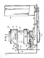
- Fig. 1 shows an embodiment of a safety device for an oil burner according to the present invention.
- An oil burner in which a safety device of the present invention is adapted to be incorporated is generally designated by reference numeral 10 and may be constructed in such a manner as widely known in the art.
- the oil burner.10 is of the wick ignition type and includes a combustion cylinder construction 12 comprising a red-heated cylinder section 14 and a flame spreading section 16 in which a white-yellow flame is formed.
- the red-heated section-14 as shown in Fig. 2, includes a perforated outer cylindrical member 18 and a perforated inner cylindrical member 20 and is adapted to carry out combustion of fuel oil vaporized from a wick.
- the flame spreading section 16 includes a flame spreader 22 which serves to burn incomplete combustion gas and unburned fuel oil gas remaining in combustion gas formed in the red-heated cylinder section 14 to form a long white-yellow flame.
- the red-heated cylinder section 14 and flame spreading section 16 are adapted to emit heat rays therefrom through heat-permeable cylinder 24 and 26 to the exterior of the oil burner 10 to heat a room, respectively.
- the red-heated cylinder section 14 may be so constructed that the outer cylindrical member 18 is covered with porcelin emanel and the inner combustion cylinder 20 is provided with a top plate or red-heated hemispherical wire-mesh member which is red-heated to emit heat rays therefrom.
- the oil burner 10 also includes an automatic fire-extinguishing device 28 disposed below the combustion cylinder construction 12.
- the oil burner 10 illustrated in Figs. 1 and 2 is the wick-ignition type wherein a wick 30 is constantly dipped at a lower portion thereof in fuel oil 32 such as kerosene received in an oil reservoir 34 communicated with an oil tank 36 invertedly supported on the reservoir 34 and adapted to be raised at an upper'end thereof into the combustion cylinder construction 12 when the combustion is to be carried out.
- the fire-extinguishing device 28 is adapted to forcedly lower the wick 30 at the time of fire-extinguishing.
- the fire-extinguishing device 28, as shown in Fig. 2 includes a wick operating shaft 38 having a knob 40 provided at one end thereof and a gear 42 freely fitted on the wick operating shaft 38.
- the device 28 also includes a return spring 44 interposed between a burner body and the gear 42 and a stopper 46 (Fig. 1) which is adapted to be engaged with the gear 42 to stop rotation of the gear, to thereby cause the spring 44 wound up when the wick operating shaft 38 is rotated in the direction of raising the wick 30 to be kept at a wound-up state.
- the automatic fire-extinguishing device 28 further includes a vibration sensing weight 48 which is connected to the stopper 46 and serves to disengage the stopper 46 from the gear 42 when it falls down due to shock such as earthquake, so that the wick operating shaft 38 may be rotated in the opposite direction due to the force of the wound-up spring 44 to lower the wick 30, to thereby accomplish the fire-extinguishing.
- the connection of the fire-extinguishing device 28 to the wick 30 may be carried out utilizing a pinion-rack mechanism 49.
- a safety device for an oil burner of the embodiment shown in Fig. 1 is adapted to be used for, for example, such an oil burner as described above and generally designated by reference numeral 50.
- the safety device 50 of the illustrated embodiment may include a heat collecting means 52 arranged to receive heat emitted from the combustion cylinder construction 12.
- the heat collecting means 52 comprises a plate member formed of a metal material and arranged laterally opposite to the combustion cylinder construction 12.
- the safety device 50 also includes an abnormal combustion sensing and actuation mechanism 54 adapted to be in response to a variation in a temperature of the combustion cylinder construction 12.
- an abnormal combustion sensing and actuation mechanism 54 adapted to be in response to a variation in a temperature of the combustion cylinder construction 12.
- the mechanism 54 includes a movable means which is adapted to be moved due to a variation in a temperature of the combustion cylinder construction 12 and may be mechanically and thermally connected to the heat collecting plate 52.
- the movable means comprises a thermally deformable element 56 formed of a material deformed depending upon a variation in temperature such as bimetal or shape memory alloy and mechanically and thermally connected to the heat collecting plate 52 and a movable member 58 attached to the deformable element 56 so as to downwardly extend therefrom.
- the movable member 58 is provided at a suitable portion thereof with an engagement means 60 which, in the illustrated embodiment, comprises a projection.
- the abnormal combustion sensing and actuation mechanism 54 further includes an actuation means 62 which is operatedly connected to the movable member 58 which is selectively actuated due to the movement of the movable member 58.
- the actuation means 62 comprises an actuation member which is pivotally mounted on a body of the oil burner 10 through a pin 64, so that it may be vertically pivotally moved about the pin 64 when the movable member 58 actuates it through the projection 60.
- the safety device of the illustrated embodiment also includes a starting means 66 operatedly connected in a manner to be selectively operated by the actuation member 62 to start the fire-extinguishing device 28 as described hereinafter when abnormal combustion forming an excessively decreased flame occurs.
- the starting means 66 comprises an extension of the stopper 46 of the fire-extinguishing device 28.
- the actuation member 62 is interposedly arranged between the movable member 58 and the starting means 66, so that it may be selectively engaged with the projection 60 of the movable member 58 to actuate the starting means 34 when the vertically extending movable member 58 is vertically moved.
- the projection 60 is adapted to be positioned below the actuation member 62-when the oil burner does not carry out combustion operation. Then, when the combustion of the oil burner starts and proceeds, the projection 60 is gradually upwardly moved with the movement of the movable member 58 as indicated by an arrow in Fig. 1 due to the deformation of the deformable member 56, during which the projection 60 abutts against the actuation member 62 to lift it. During the combustion operation of the oil burner, the projection 60 is held at a position above the actuation member 62 as indicated by dotted lines in Fig. 1.
- the projection 60 is lowered with the lowering of the movable member 58 to pivotally move the actuation member 62 about the pin 64 in the counterclockwise direction to actuate the starting means 66, resulting in the fire-extinguishing device 22 being started, and then positioned below the actuation member 62.
- the projection 60 of the movable member 58 is further lowered because the thermally deformable element 56 is further cooled to a room temperature.
- the safety device of illustrated embodiment is adapted not to actuate the fire-extinguishing device 62, even when the projection 60 is lowered below the actuation member 62. More particularly, when the projection 60 of the movable member 58 is lowered to a low temperature position below the actuation member 62 the actuation member 62, as shown in Fig. 3A, is pivotally moved about the pin 64 in the direction separated from the projection 60 in arcs, so that it may be released from the projection 60.
- the abnormal combustion sensing and actuation mechanism 54 reaches such a position as indicated at phantom lines in Fig. 1.
- the fire-extinguishing device 28 is kept stationary because the actuation member 62 does not actuate the starting member 66, so that the engagement between the gear 42 and the stopper 46 is not released.
- the projection 60 fails to contact with the actuation member 62, because the locus of movement of the projection 60 is linear, whereas that of the actuation member 62 is arcuate.
- the actuation member 62 is at a position shown in Fig. 3C.
- the manual fire-extinguishing is carried out by rotating the wick operating shaft 38 in the opposite direction, during which the engagement between the gear 42 and the stopper 46 is kept, to thereby keep the spring 44 at a wound-up state.
- the projection 60 is downwardly moved while pivotally moving the actuation member 62 in the counterclockwise direction as shown in Fig. 3D and finally returns to the position shown in Fig. 3A.
- the actuation member 62 is rotated in the counterclockwise direction as described above, so that it may actuate the starting member 66 as shown in Fig. 3D, resulting in the stopper being actuated.
- This causes the gear 42 to be disengaged from the stopper 46 and reversely rotated by the wound-up return spring 44 to be returned to the original position.
- the projection 60 and actuation member 62 are at the position shown in Fig. 3A; accordingly, the projection 60 fails to contact with the actuation member 62 when it is upwardly moved again for the purpose of ignition, because the member 62 has been pivotally moved in the direction separated from the projection 60 in arcs.
- the oil burner may be ignited again by repeating the ignition procedures described above.
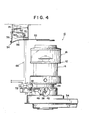
- Fig. 4 shows a modification of the embodiment shown in Fig. 1.
- the modification shown in Fig. 4 is adapted to operate an automatic fire-extinguishing device 28 of an oil burner 10 through an electrically constructed starting means 66 when the abnormal combustion occurs.
- the starting means 66 comprises a micro switch 70 arranged above a combustion cylinder construction 12 and a solenoid 72 electrically connected to the micro switch 70 and arranged adjacent to a vibration sensing weight 48 to actuate the weight 48.
- An abnormal combustion sensing and actuation mechanism 54 further comprises a deformable element 56 arranged below the micro switch 70 and mechanically and thermally connected to a heat collecting means 52 arranged just above the combustion cylinder construction 12, a movable member 58 mounted on the deformable member 56 so as to upwardly extend therefrom and provided with a projection 60, and an actuation member 62 counted on the micro switch 70 so as to be engaged with the projection 60 and operatedly connected to the micro switch 70.
- the heat collecting means 52 may comprise a plate member formed of a metal material into a suitable shape such as an annular shape, a circular shape or the like. Also, the modification shown in Fig.
- the projection 60 is preferably formed to upwardly obliquely extend from the movable member 58 toward the actuation member 62 for the purpose of ensuring the smooth engagement between the projection 60 and the actuation member 62.
- the actuation member 62 mounted on the micro switch 70 is regulated to carry out the pivotal movement at a small angle as compared with the embodiment of Fig. 1. More particularly, the pivotal movement of the actuation member 62 is limited to a range within which the member 62 is moved by the vertical movement of the movable member 58, so that when the movable member 58 upwardly moves to lift the actuation member 62, the projection 60 of the member 58 which is upwardly moved outwardly escapes from the actuation member 62 while moving along the member 62. This results in the movable member 58 being slightly rotated in the counterclockwise direction in Fig. 4 about the the lower end thereof against the compression spring 74.
- the projection 60 is upwardly moved to a position above the actuation member 62 with the progress of combustion of the oil burner.
- the movable member 58 is lowered, during which the projection 60 of the movable member 58 downwardly pushes the actuation member 62 to turn on the micro switch 70.
- the downward pivotal movement of the actuation member 62 is limited to such a position. Accordingly, the projection 60 escapes from the actuation member 62 during the lowering of the movable member while moving along the member 62. This results in the movable member 58 being slightly rotated in the counterclockwise direction in Fig. 4 about the the lower end thereof against the compression spring 74. Then, the projection 60 is lowered to a position below the actuation member 62 with the downward movement of the movable member 58.
- Fig. 5 shows another embodiment of a safety device for an oil burner according to the present invention.
- a movable member 58 is connected directly to an actuation member 62, so that the vertical movement of the movable member 58 may pivotally move the actuation member 62 about a pin 64.
- the embodiment illustrated lacks an engagement means such as the projection 60 in the first embodiment.
- the actuation member 62 comprises an actuation member body 76 selectively abutted against a starting means 66 and a leaf spring 78 mechanically connected to the actuation member body 76 and fittedly engaged directly with the movable member 58.
- An abnormal combustion sensing and actuation mechanism 54 also includes a timer 80 and a lever 82 for operating the timer which are mounted on an oil burner 10, and a cam plate 84 fitted on a wick operating shaft.
- the cam plate 84 acts to set the timer operating lever 82 at the wick lowering position of the wick operating shaft 38.
- the timer operating lever 82 is formed integral with a cam 86 for the timer 80, which is formed with a recess 88.
- Reference'numeral 90. designates a lever which is pivotally mounted at one end thereof on the timer 80 and is provided with a projection 92 adapted to be engaged with the recess 88 of the timer cam 86.
- an abnormal combustion sensing and actuation mechanism 54 includes an actuation rod 96 connected between a lower end of the push lever 94 and a lower end of the lever 90.
- the push lever 94 serves to hold the actuation means 62 at a position separated from the the starting means 66 against the leaf spring 78 at the time of setting the timer 80.
- the oil burner 10 starts combustion.
- This causes the movable member 58 to be lifted to straighten the leaf spring 78 as indicated at phantom lines in Fig. 5, during which the cam plate 84 is moved in the direction separated from the timer operating lever 82 to actuate the timer 80.
- the illustrated embodiment is so constructed that even when the cam plate 84 is moved away from the timer operating lever 82, the timer is adapted to pivotally move the timer operating lever and timer cam in a predetermined period of time, accordingly, the actuation rod 96 is held at a pushed position for about ten to fifteen minutes until the mechanism 54 detects a high temperature. After about ten to fifteen minutes, the projection 92 of the lever 90 is fitted in the recess 88 of the timer cam 86 to rotate the push lever 94 in the counterclockwise direction.
- the cam plate 84 rotates the timer operating lever 82 in the clockwise direction to reset the lever 82. This releases the engagement between the recess 88 of the timer cam 86 and the projection 92 of the lever 90, so that the push lever 94 may be rotated in the clockwise direction through the actuation rod 96 to return to the position shown in Fig. 5.
- the movable member 58 When abnormal combustion occurs during the normal combustion operation of the oil burner, the movable member 58 is lowered, during which the push lever 94 is kept at the position obtained due to the above-described counterclockwise rotation. Accordingly, the actuation member 62 is at a state separated from the push lever 94, so that the fire-extinguishing device starts. This results in the wick operating shaft 38 being rotated in the direction of lowering the wick. At this time, the push lever 94 is rotated in the clockwise direction to bend the leaf spring 78.
- Fig. 6 shows a modification of the embodiment shown in Fig. 5.
- the modification shown in Fig. 6 is adapted to operate an automatic fire-extinguishing device 28 through an electrically constructed starting means 66 when the abnormal combustion occurs, as in the modification shown in Fig. 4.
- the starting means 66 comprises a micro switch 70 arranged above a combustion cylinder construction 12 and a solenoid 72 electrically connected to the micro switch 70 and arranged adjacent to a vibration sensing weight 48 of a fire-extinguishing device 28 to actuate the weight 48.
- An abnormal combustion sensing and actuation mechanism 54 further comprises a heat collecting means 52 arranged just above the combustion cylinder construction 12, a deformable element 56 arranged below the micro switch 70 and mechanically and thermally connected to the heat collecting means 52, and an actuation member 62 mounted on a lower surface of the micro switch 70 so as to allow the deformable element 56 to be abutted against the actuation member 62 when the element 56 is deformed due to a variation in temperature.
- the deformable element 56 also acts as a member corresponding to the movable member 58 in the embodiment described above.
- the heat collecting means 52 comprises a plate member formed of a metal material into a suitable shape such as an annular shape, a circular shape or the like.
- the modification is constructed in such a manner that a cam plate 84 of a wick operating shaft 38 turns off a timer switch 98 through a timer operating lever 82 at the wick lowering position of the wick operating shaft 38, to thereby open a contact of the timer 80, so that an electric circuit between the micro switch 70 and the solenoid 72 is opened to set a fire-extinguishing device 28.
- the timer 80 acts to feed-an electric current to the micro switch 70 and solenoid 72 in a predetermined period of time.
- the electric circuit is kept at an interrupted state for ten to fifteen minutes until the mechanism 54 detects a high temperature sufficient to actuate the micro switch 70.
- the embodiments described above each are capable of effectively detecting excessively decreased combustion due to, for example, the adhering of much tar to the wick; the excessive lowering of the wick, the clogging of an air rectifying plate and/or air filter with dust, the deficiency of air in a room or the like to cause the fire-extinguishing device to be automatically actuated, to thereby provide the oil burner with sufficiently improved safety.
- the above-described embodiments each are adapted to allow the fire-extinguishing device to be placed at a state to be reset when the fire-extinguishing is carried out, to thereby carry out in the operation of the oil burner with ease.
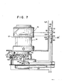
- Fig. 7 shows a further embodiment of a safety device for an oil burner according to the present invention.
- a safety device of the illustrated embodiment generally designated by reference numeral 50
- an abnormal combustion sensing and actuation mechanism indicated by 54' utilizes a heat ray sensing means which is generally designated by reference numeral 100.
- the safety device 50 of the illustrated embodiment may include a heat reflection plate 52' arranged opposite to a combustion cylinder construction 12.
- the abnormal combustion sensing and actuation mechanism 54' includes a heat ray sensing means 100 which, in the illustrated embodiment, is arranged behind the heat reflection plate 52' and directly opposite to the combustion cylinder construction 12 through an opening 102 of the heat reflection plate 52'.
- the sensing means 100 is arranged opposite to a red-heated cylinder section 14 of the combustion cylinder construction 12.
- the heat ray sensing means 100 has a guide tube 104 mounted on a front surface thereof which serves to specify a heat ray emitting position of the cylinder section 14.
- the heat ray sensing means 100 serves to detect heat rays emitted from the red-heated and convert the so-detected heat rays into an electrical signal.
- the heat ray sensing means 100 also generates a heat ray non-detection signal while it does not detect heat rays and a heat ray detection signal while it detects heat rays.
- a sensing element for the heat ray sensing means 100 is conveniently used an element which is capable of detecting visible rays as well as heat rays, such as a photoconductive cell including a phototransistor, a cadmium sulfide cell and the like.
- an element adapted to sense only heat rays may be used for the heat ray sensing means 100 as well.
- the abnormal combustion sensing and actuation mechanism 54' also includes an actuation means 62 for starting a fire-extinguishing device 28 of the oil burner through a starting means 66, the actuation means 62 being adapted to be actuated by a signal supplied from the heat ray sensing means 100 through an output terminal 106 thereof.
- the actuation means 62 comprises a heater 108 actuating when an electrical current (heat ray non-detection signal) is supplied thereto through the output terminal 106 of the heat ray sensing means 100, a projection 110, and a deformable member 112 formed of bimetal and adapted to be invertedly moved in one or two seconds to lift the projection 110 when it is heated by the heater 108.
- the actuation means 62 is adapted to lift one end of the starting means 66 through the projection 110 to actuate when the projection is pushed up, to thereby operate the fire-extinguishing device 28.
- the abnormal combustion sensing and actuation mechanism 54' also includes a cam plate 84 fitted on a wick operating shaft 38 of the fire-extinguishing device 28, the cam plate 84 serving to turn off a main switch 98 for controlling the start of a timer 80 described hereinafter when the wick operating shaft 38 is at a wick lowering position.
- the main switch 98 is turned on when the wick operating shaft is rotated to a wick ignition position shown in Fig. 7.
- the embodiment shown in Fig. 7 may be constructed to include a second abnormal combustion sensing and actuation mechanism 114 which is adapted to detect abnormal combustion which forms an excessively increased flame which is in danger of, for example, overheating of the oil burner and/or a fire.
- the second mechanism 114 includes a second heat ray sensing means 116 which has a sensing element arranged opposite to the combustion cylinder construction 12 through an opening of the heat reflection plate 52'.
- the second heat ray sensing means 116 is arranged above the first heat ray sensing means 100 and opposite to a flame spreading section 16.
- the second heat ray sensing means 116 also has a guide tube 120 mounted on a front surface thereof which serves to specify a heat ray emitting position of the flame spreading section 16.
- the second heat ray sensing means 116 is to detect a height of a flame formed at the flame spreading section, thus, it preferably has precision higher than the first one 100.
- heat rays which have been incident into the guide tube 120 in a manner to be oblique with respect to an opening of the tube 120 is apt to cause malfunction of the senser 116, because the heat rays reach the senser 116 while reflecting on ar. inner surface of the tube 120.
- a top of the flame exhibits high luminance.
- the guide tube 120 is desirably formed to have a small diameter.
- the second heat ray sensing means 116 is adapted to detect heat rays emitted from a flame formed at the flame spreading section 16 to generate a heat ray detection signal for actuating the actuation means 62, when the flame is excessively increased to a degree sufficient to reach a predetermined position.
- the second abnormal combustion sensing and actuation mechanism 114 also may include an alarm 122 such as a buzzer or the like, which is adapted to be actuated when a heat ray detection signal is generated from the second heat ray sensing means 116.
- the alarm 122 may be constructed in any desired manner. For example, it may be so constructed that it is actuated in a predetermined period of time before the actuation means 62 is actuated, to thereby call a user's attention. Such construction allows the manual adjustment of combustion due to the wick lowering operation to be effectively carried out before the automatic fire-extinguishing operation is carried out through the actuation means 62, when an operator is near the oil burner.
- Fig. 8 shows one example of an electric circuit which may be employed in the embodiment of Fig. 7 in relation to the first and second abnormal combustion sensing and actuation mechanisms 54' and 114.
- the turning-on of the main switch 98 causes the timer 80 to be connected to a power source (not shown).
- the timer 80 used in the illustrated embodiment is a CR timer in which a capacitor and resistors are used.
- the timer 80 comprises a series circuit comprising a resistor Rl and a capacitor C connected in parallel to an output terminal of the power source (not shown), a diode D1, a Zener diode ZD of which a cathode is connected to a connection between the resistor Rl and the capacitor C, a transistor Trl of which a cathode-emitter circuit is connected in series to the switch 98, a resistor R2 of which one end is connected to a base of the transistor Trl, and a transistor Tr2 of which a collector is connected to the other end of the resistor R2, a base is connected to an anode of the Zener diode ZD and an emitter is grounded.
- the timer 80 feeds an output of the power source (not shown) therethrough to the first and second heat ray sensing means 100 and 116, the actuation means 62, and the alarm 122.
- the timer 80 is determined to have a time interval longer than a time required from ignition to the generation of heat rays of a predetermined intensity at the portion of the combustion cylinder construction to which the first heat ray sensing means 100 is arranged opposite.
- the first heat ray sensing means 100 includes a phototransistor PTrl serving as an element for detecting heat rays emitted from the combustion cylinder construction 12.
- the phototransistor PTrl is connected through a resistor R41 to a collector of the transistor Trl of the timer 80.
- a collector-emitter circuit of the phototransistor PTrl is connected in parallel to a base- collector circuit of a transistor Tr41 for amplification.
- a collector of the transistor Tr41 is connected through a resistor R42 to a positive terminal of an operational amplifier OP1 acting as a comparator.
- To a negative terminal of the operational amplifier OP1 is connected the connection between a resistor R43 and a resistor R44.
- a series circuit comprising the resistors R43 and R44 constitutes a reference voltage generating circuit which serves to generate a reference voltage for carrying out distinction between heat rays to be detected'and disturbance light which enter a base of the phototransistor PTrl.
- the so-generated reference voltage is determined to have a value larger than a detection voltage supplied to the positive terminal of the operational amplifier OP1 when only disturbance light enters the phototransistor and smaller than a detection voltage supplied to the positive terminal when heat rays enter it.
- An output of the operational amplifier OP1 is decreased to a low level or a ground level when an input .
- voltage supplied to the positive terminal is equal to or above the reference voltage fed to the negative terminal and increased to a high level when the input voltage is lower than the reference voltage.
- the voltage input to the positive terminal of the operational amplifier OP1 is decreased below the reference voltage. This causes an electric current to flow from the power source through the resistors R45, R46 and R47, so that a current may flow through a base of a transistor Tr42 to turn on the transistor Tr42.
- the phototransistor PTrl detects heat rays
- the voltage supplied to the positive terminal is decreased above the reference voltage. This causes an output of the operational amplifier OP1 to be at a ground level to turn off the transistor Tr42, so that the actuation means 62 may not be actuated.
- the second heat ray sensing means 116 is constructed in substantially the same manner as the first one 100 except for that the manner of input to positive and negative terminals of an operational amplifier OP2 is opposite to that in the operational amplifier OP1 and an output of the operational amplifier OP2 is opposite to that of the operational amplifier OP1.
- a phototransistor PTr2 of the second heat ray sensing means 100 is turned on to cause an input voltage fed to a negative terminal of the operational amplifier OP2 to be increased above a reference voltage fed to a positive terminal of the operational amplifier OP2.
- the heat ray sensing means 100 and 116, actuation means 62, and alarm 122 are electrically isolated from the power source unless the timer 80 counts a predetermined time period or interval. Accordingly, even when a temperature of the combustion cylinder-construction 12 remains low because of immediately after the ignition or combustion is not sufficient to cause the heat ray sensing means 100 to detect heat rays, the fire-extinguishing is not operated because the heat ray sensing means 100 is kept at a non-operation state.
- a temperature of the combustion cylinder construction 12 is kept low even after the timer 80 completes the counting operation. This causes the heat ray sensing means 100 which has reached an operable state to generate a signal from the output terminal 106, so that the actuation means 62 may be actuated to operate the fire-extinguishing device 28 through the starting means 66.
- Fig. 9 is a circuit diagram showing a modification of the timer 80.
- a timer 80 shown in Fig. 9 when the main switch 98 is closed, a current flows through a heating element 124 comprising a resistor, so that the heating element 124 may heat bimetal 126 arranged adjacent thereto.
- the so-heated bimetal straightly extends in a few'minutes to contact a movable contact 130 with a fixed contact 128, to thereby connect the heat ray sensing means 100 and 116 to the power source.
- the timer 80 of Fig. 9 is a bimetal timer in which the bimetal'126 is adapted to determine a time interval.
- the heat ray sensing means 100 and 116 each may include a filter which is capable of passing only'light of a predetermined wavelength therethrough to detect only heat rays .
- the embodiment shown in Fig. 7 as well as the embodiments shown in Figs. 1 to 6 is capable of effectively detecting excessively decreased combustion forming incomplete combustion gas such as carbon monoxide due to the adhesion of much tar to the wick, the excessive lowering of the wick in the combustion operation, the clogging of an air rectifying plate or air filter with dust, the deficiency of oxygen in a room to automatically operate the fire-extinguishing device, so that the oil burner may be provided with highly improved safety.
- the embodiment is constructed to utilize heat rays for detecting abnormal combustion in the oil burner. This allows the heat ray sensing means to be arranged at any desired position so long as it can detect heat rays, to thereby simplify the structure of the oil burner.
- the embodiment is capable of detecting both abnormal combustion forming an excessively decreased flame and that forming an excessively increased flame, because the detection of heat rays provides an oil burner with a place sufficient to allow the heat ray sensing means detecting excessively decreased combustion as well as that detecting excessively decreased combustion to be arranged.
Landscapes
- Engineering & Computer Science (AREA)
- Chemical & Material Sciences (AREA)
- Combustion & Propulsion (AREA)
- Mechanical Engineering (AREA)
- General Engineering & Computer Science (AREA)
- Regulation And Control Of Combustion (AREA)
- Feeding And Controlling Fuel (AREA)
- Control Of Combustion (AREA)
Priority Applications (1)
| Application Number | Priority Date | Filing Date | Title |
|---|---|---|---|
| AT86303302T ATE84133T1 (de) | 1985-04-30 | 1986-04-30 | Oelbrenner mit sicherheitsvorrichtung. |
Applications Claiming Priority (4)
| Application Number | Priority Date | Filing Date | Title |
|---|---|---|---|
| JP93445/85 | 1985-04-30 | ||
| JP60093445A JPS61252429A (ja) | 1985-04-30 | 1985-04-30 | 石油燃焼器の安全装置 |
| JP254513/85 | 1985-11-12 | ||
| JP60254513A JPS62112921A (ja) | 1985-11-12 | 1985-11-12 | 石油燃焼器の安全装置 |
Publications (3)
| Publication Number | Publication Date |
|---|---|
| EP0200549A2 true EP0200549A2 (de) | 1986-11-05 |
| EP0200549A3 EP0200549A3 (en) | 1988-08-31 |
| EP0200549B1 EP0200549B1 (de) | 1992-12-30 |
Family
ID=26434811
Family Applications (1)
| Application Number | Title | Priority Date | Filing Date |
|---|---|---|---|
| EP86303302A Expired - Lifetime EP0200549B1 (de) | 1985-04-30 | 1986-04-30 | Ölbrenner mit Sicherheitsvorrichtung |
Country Status (7)
| Country | Link |
|---|---|
| US (1) | US4797088A (de) |
| EP (1) | EP0200549B1 (de) |
| KR (1) | KR900000950B1 (de) |
| AT (1) | ATE84133T1 (de) |
| DE (1) | DE3687363T2 (de) |
| DK (1) | DK167549B1 (de) |
| NO (1) | NO166895C (de) |
Cited By (2)
| Publication number | Priority date | Publication date | Assignee | Title |
|---|---|---|---|---|
| GB2328276A (en) * | 1997-08-14 | 1999-02-17 | Waterford Foundry | Oil-fired stove |
| EP3002516A1 (de) * | 2014-09-30 | 2016-04-06 | Paseco Co., Ltd. | Heizer mit automatischem feuerlöscher |
Families Citing this family (16)
| Publication number | Priority date | Publication date | Assignee | Title |
|---|---|---|---|---|
| NZ222930A (en) * | 1987-12-15 | 1990-08-28 | Moffat Appliances Ltd | Gas infra-red burner in heat exchanger |
| US5057005A (en) * | 1989-05-25 | 1991-10-15 | Kwok Wai Shi | Candle device |
| US5080578A (en) * | 1991-02-12 | 1992-01-14 | Harold Josephs | Liquid fuel burning heater having flame stopping means |
| US5338185A (en) * | 1993-10-04 | 1994-08-16 | Southeastern Research Laboratories, Inc. | Safety device for preventing uncontrolled flareup in wick-fed liquid fuel burners |
| US5456595A (en) * | 1994-05-23 | 1995-10-10 | Henderson; Richard W. | Device for preventing flareup in barometric-type wick-fed liquid fuel burners |
| US5409370A (en) * | 1994-09-30 | 1995-04-25 | Henderson; Richard W. | Liquid fuel burner safety device employing fuel tank shutoff |
| US5549470A (en) * | 1994-12-29 | 1996-08-27 | Henderson; Richard W. | Anti-flareup device for liquid fuel burners |
| US5662468A (en) * | 1995-08-14 | 1997-09-02 | Henderson; Richard W. | Device that prevents flareup in liquid fuel burners |
| US5551865A (en) * | 1995-11-17 | 1996-09-03 | Henderson; Richard W. | Safety shut-off device for liquid fuel burners |
| US5772425A (en) * | 1996-07-19 | 1998-06-30 | Henderson; Richard W. | Device for preventing flareup in liquid fuel burners by containing sump vapors |
| US5730115A (en) * | 1996-07-19 | 1998-03-24 | Henderson; Richard W. | Device for preventing flareup in liquid fuel burners by regulating fuel flow into the fuel chamber |
| US5899682A (en) * | 1997-03-31 | 1999-05-04 | Henderson; Richard W. | Device for preventing flareup in liquid fuel burners by regulating fuel flow from the removable fuel tank |
| US5967765A (en) * | 1997-08-19 | 1999-10-19 | Henderson; Richard W. | Device for preventing flareup in liquid-fuel burners by providing constant-rate fuel flow from removable fuel tank |
| US6254380B1 (en) | 2000-05-30 | 2001-07-03 | Richard W. Henderson | Device for preventing flareup in barometric-type liquid fuel burners by preventing excessive temperature levels at removable fuel tank |
| KR100381256B1 (ko) * | 2000-06-09 | 2003-04-23 | 주식회사 파세코 | 자동소화장치 |
| ES1135492Y (es) * | 2014-12-11 | 2015-04-13 | Eika S Coop | Foco radiante adaptado a una encimera de cocción |
Family Cites Families (10)
| Publication number | Priority date | Publication date | Assignee | Title |
|---|---|---|---|---|
| US2074637A (en) * | 1936-06-01 | 1937-03-23 | Solar Ind Inc | Flame failure indicator |
| US2363443A (en) * | 1941-05-15 | 1944-11-21 | Servel Inc | Wick type oil burner control |
| US2640920A (en) * | 1949-07-09 | 1953-06-02 | Gen Controls Co | Safety fuel burner control system utilizing flame conduction |
| GB908973A (en) * | 1960-05-21 | 1962-10-24 | Sankey & Sons Ltd Joseph | Improvements relating to oil-burning space-heating appliances |
| US3301307A (en) * | 1963-11-12 | 1967-01-31 | Ngk Insulators Ltd | Device for detecting the configuration of a burning flame |
| JPS5630520A (en) * | 1979-08-20 | 1981-03-27 | Matsushita Electric Ind Co Ltd | Safety device for combusting apparatus |
| US4493634A (en) * | 1982-04-28 | 1985-01-15 | Yang Jerry S C | Kerosene heating stove with temperature and carbonic oxide sensors |
| JPS5937628A (ja) * | 1982-08-25 | 1984-03-01 | 松下電工株式会社 | オイルダツシユポツト |
| JPS5987518U (ja) * | 1982-11-27 | 1984-06-13 | 株式会社トヨトミ | 石油燃焼器の芯高調節装置 |
| JPS59139754U (ja) * | 1983-03-04 | 1984-09-18 | 株式会社トヨトミ | バ−ナの安全装置 |
-
1986
- 1986-04-28 NO NO861654A patent/NO166895C/no not_active IP Right Cessation
- 1986-04-29 US US06/857,013 patent/US4797088A/en not_active Expired - Lifetime
- 1986-04-30 DE DE8686303302T patent/DE3687363T2/de not_active Expired - Lifetime
- 1986-04-30 DK DK197886A patent/DK167549B1/da not_active IP Right Cessation
- 1986-04-30 KR KR1019860003346A patent/KR900000950B1/ko not_active Expired
- 1986-04-30 AT AT86303302T patent/ATE84133T1/de not_active IP Right Cessation
- 1986-04-30 EP EP86303302A patent/EP0200549B1/de not_active Expired - Lifetime
Cited By (4)
| Publication number | Priority date | Publication date | Assignee | Title |
|---|---|---|---|---|
| GB2328276A (en) * | 1997-08-14 | 1999-02-17 | Waterford Foundry | Oil-fired stove |
| GB2328276B (en) * | 1997-08-14 | 1999-10-27 | Waterford Foundry | Oil-fired stove |
| EP3002516A1 (de) * | 2014-09-30 | 2016-04-06 | Paseco Co., Ltd. | Heizer mit automatischem feuerlöscher |
| CN105465826A (zh) * | 2014-09-30 | 2016-04-06 | 帕饰克股份有限公司 | 具有自动熄火器的加热器 |
Also Published As
| Publication number | Publication date |
|---|---|
| EP0200549B1 (de) | 1992-12-30 |
| NO861654L (no) | 1986-10-31 |
| US4797088A (en) | 1989-01-10 |
| EP0200549A3 (en) | 1988-08-31 |
| NO166895C (no) | 1991-09-11 |
| DK167549B1 (da) | 1993-11-15 |
| KR900000950B1 (ko) | 1990-02-19 |
| DK197886D0 (da) | 1986-04-30 |
| ATE84133T1 (de) | 1993-01-15 |
| NO166895B (no) | 1991-06-03 |
| DE3687363T2 (de) | 1993-04-29 |
| DK197886A (da) | 1986-10-31 |
| KR860008408A (ko) | 1986-11-15 |
| DE3687363D1 (de) | 1993-02-11 |
Similar Documents
| Publication | Publication Date | Title |
|---|---|---|
| EP0200549B1 (de) | Ölbrenner mit Sicherheitsvorrichtung | |
| US5165883A (en) | Apparatus and method for safe operation of kerosene heaters | |
| US4482311A (en) | Burner with oxygen shortage sensor | |
| US4664095A (en) | Safety device for open-type combustor | |
| US4790745A (en) | Automatic fire-extinguishing device for oil burner | |
| US4534727A (en) | Liquid fuel burner having an oxygen sensor located in a flame | |
| CA1215314A (en) | Oil heating equipment | |
| JPS5896924A (ja) | 燃焼器の酸欠安全装置 | |
| JPS58203319A (ja) | 燃焼器の酸欠安全装置 | |
| EP0719985B1 (de) | Ölbrenner mit automatischer Verbrennungsreduktion | |
| JPS6146732B2 (de) | ||
| JPH018855Y2 (de) | ||
| JPS63217133A (ja) | 開放型燃焼器の安全装置 | |
| JPS63131920A (ja) | 石油燃焼器 | |
| JPS63217132A (ja) | 開放型燃焼器の安全装置 | |
| JPS6157530B2 (de) | ||
| IE72463B1 (en) | A process of monitoring and ensuring the safe operation of unvented stoves particularly kerosene stoves and apparatus for practising said process | |
| JPS623602Y2 (de) | ||
| JPS63217135A (ja) | 開放型燃焼器の安全装置 | |
| JPS63217137A (ja) | 開放型燃焼器の安全装置 | |
| JPS6151209B2 (de) | ||
| JPS58184426A (ja) | 燃焼器 | |
| JPS6123293B2 (de) | ||
| JPS63267831A (ja) | 開放型燃焼器の安全装置 | |
| JPS63267823A (ja) | 開放型燃焼器の安全装置 |
Legal Events
| Date | Code | Title | Description |
|---|---|---|---|
| PUAI | Public reference made under article 153(3) epc to a published international application that has entered the european phase |
Free format text: ORIGINAL CODE: 0009012 |
|
| AK | Designated contracting states |
Kind code of ref document: A2 Designated state(s): AT BE CH DE FR GB IT LI LU NL SE |
|
| RAP1 | Party data changed (applicant data changed or rights of an application transferred) |
Owner name: TOYOTOMI KOGYO CO., LTD. |
|
| PUAL | Search report despatched |
Free format text: ORIGINAL CODE: 0009013 |
|
| AK | Designated contracting states |
Kind code of ref document: A3 Designated state(s): AT BE CH DE FR GB IT LI LU NL SE |
|
| 17P | Request for examination filed |
Effective date: 19890226 |
|
| 17Q | First examination report despatched |
Effective date: 19890629 |
|
| RAP3 | Party data changed (applicant data changed or rights of an application transferred) |
Owner name: TOYOTOMI CO., LTD. |
|
| RAP1 | Party data changed (applicant data changed or rights of an application transferred) |
Owner name: TOYOTOMI KOGYO CO., LTD. |
|
| GRAA | (expected) grant |
Free format text: ORIGINAL CODE: 0009210 |
|
| ITF | It: translation for a ep patent filed | ||
| AK | Designated contracting states |
Kind code of ref document: B1 Designated state(s): AT BE CH DE FR GB IT LI LU NL SE |
|
| REF | Corresponds to: |
Ref document number: 84133 Country of ref document: AT Date of ref document: 19930115 Kind code of ref document: T |
|
| ET | Fr: translation filed | ||
| REF | Corresponds to: |
Ref document number: 3687363 Country of ref document: DE Date of ref document: 19930211 |
|
| PLBE | No opposition filed within time limit |
Free format text: ORIGINAL CODE: 0009261 |
|
| STAA | Information on the status of an ep patent application or granted ep patent |
Free format text: STATUS: NO OPPOSITION FILED WITHIN TIME LIMIT |
|
| 26N | No opposition filed | ||
| EPTA | Lu: last paid annual fee | ||
| EAL | Se: european patent in force in sweden |
Ref document number: 86303302.3 |
|
| REG | Reference to a national code |
Ref country code: GB Ref legal event code: IF02 |
|
| PGFP | Annual fee paid to national office [announced via postgrant information from national office to epo] |
Ref country code: GB Payment date: 20050422 Year of fee payment: 20 |
|
| PGFP | Annual fee paid to national office [announced via postgrant information from national office to epo] |
Ref country code: IT Payment date: 20050426 Year of fee payment: 20 |
|
| PGFP | Annual fee paid to national office [announced via postgrant information from national office to epo] |
Ref country code: DE Payment date: 20050428 Year of fee payment: 20 |
|
| PGFP | Annual fee paid to national office [announced via postgrant information from national office to epo] |
Ref country code: SE Payment date: 20050429 Year of fee payment: 20 Ref country code: NL Payment date: 20050429 Year of fee payment: 20 Ref country code: FR Payment date: 20050429 Year of fee payment: 20 Ref country code: AT Payment date: 20050429 Year of fee payment: 20 |
|
| PGFP | Annual fee paid to national office [announced via postgrant information from national office to epo] |
Ref country code: CH Payment date: 20050503 Year of fee payment: 20 |
|
| PGFP | Annual fee paid to national office [announced via postgrant information from national office to epo] |
Ref country code: BE Payment date: 20050511 Year of fee payment: 20 |
|
| PGFP | Annual fee paid to national office [announced via postgrant information from national office to epo] |
Ref country code: LU Payment date: 20050601 Year of fee payment: 20 |
|
| PG25 | Lapsed in a contracting state [announced via postgrant information from national office to epo] |
Ref country code: GB Free format text: LAPSE BECAUSE OF EXPIRATION OF PROTECTION Effective date: 20060429 |
|
| PG25 | Lapsed in a contracting state [announced via postgrant information from national office to epo] |
Ref country code: NL Free format text: LAPSE BECAUSE OF EXPIRATION OF PROTECTION Effective date: 20060430 |
|
| REG | Reference to a national code |
Ref country code: GB Ref legal event code: PE20 |
|
| REG | Reference to a national code |
Ref country code: CH Ref legal event code: PL |
|
| NLV7 | Nl: ceased due to reaching the maximum lifetime of a patent |
Effective date: 20060430 |
|
| EUG | Se: european patent has lapsed | ||
| BE20 | Be: patent expired |
Owner name: *TOYOTOMI KOGYO CO. LTD Effective date: 20060430 |