EP0200439A2 - Drehbarer Typenträger und Auswahlvorrichtung für eine Druckeinheit in Schreibmaschinen - Google Patents
Drehbarer Typenträger und Auswahlvorrichtung für eine Druckeinheit in Schreibmaschinen Download PDFInfo
- Publication number
- EP0200439A2 EP0200439A2 EP86302946A EP86302946A EP0200439A2 EP 0200439 A2 EP0200439 A2 EP 0200439A2 EP 86302946 A EP86302946 A EP 86302946A EP 86302946 A EP86302946 A EP 86302946A EP 0200439 A2 EP0200439 A2 EP 0200439A2
- Authority
- EP
- European Patent Office
- Prior art keywords
- character
- carrying member
- plates
- disc
- carrying
- Prior art date
- Legal status (The legal status is an assumption and is not a legal conclusion. Google has not performed a legal analysis and makes no representation as to the accuracy of the status listed.)
- Granted
Links
Images

Classifications
-
- B—PERFORMING OPERATIONS; TRANSPORTING
- B41—PRINTING; LINING MACHINES; TYPEWRITERS; STAMPS
- B41J—TYPEWRITERS; SELECTIVE PRINTING MECHANISMS, i.e. MECHANISMS PRINTING OTHERWISE THAN FROM A FORME; CORRECTION OF TYPOGRAPHICAL ERRORS
- B41J1/00—Typewriters or selective printing mechanisms characterised by the mounting, arrangement or disposition of the types or dies
- B41J1/22—Typewriters or selective printing mechanisms characterised by the mounting, arrangement or disposition of the types or dies with types or dies mounted on carriers rotatable for selection
- B41J1/24—Typewriters or selective printing mechanisms characterised by the mounting, arrangement or disposition of the types or dies with types or dies mounted on carriers rotatable for selection the plane of the type or die face being perpendicular to the axis of rotation
- B41J1/243—Mounting or fixing the carriers
Definitions
- the present invention relates to a rotary character-carrying member and the selector device therefor for a print unit of typing machines and in particular electronic typewriters, comprising a motor shaft which can be positioned in a plurality of angular positions and in which the character-carrying member can be removably connected to the motor shaft and is provided with identification eie- ments disposed in a coded fashion along a circular ring thereon.
- Typewriters which use character-carrying members with identification elements are generally provided with a detection or recognition circuit which, in an initialisation phase of the machine, provides for rotary movement of the character-carrying member and for recognition of some characteristic parameters of the character-carrying member, thus simplifying use of the machine.
- the character-carrying member is of the daisywheel type, in which the motor shaft is rotated by a stepping motor and in which the circuit for recognition of the identification elements detects the coded position of the identification elements, recognises a particular reference position of the character-carrying member and activates the motor for a number of steps such as to position the character-carrying daisywheel in its zero position.
- That arrangement requires a recognition circuit which has a high degree of angular resolution and positioning of the identification elements which is so accurate as to discriminate the reference position with a maximum error that is less than half the angular step of the character-carrying petals. That is necessary in order to avoid the zero position of the daisywheel being associated with a different petal from the predetermined petal.
- the character-carrying daisywheel and the recognition circuit are therefore rather expensive.
- the object problem of the present invention is to provide a character-carrying member provided with identification elements, and the selector device therefor, which are reliable and of restricted cost both individually and jointly.
- the selector arrangement which, in accordance with a first characteristic thereof, comprises a position transducer having a movable portion synchronous with the character-carrying member and a detection portion which generates a position signal having a period which is double the angular spacing of two adjacent characters of the character-carrying member.
- a zeroing circuit which is controlled by the recognition circuit coarsely positions the character-carrying member in a zero area associated with the reference positions of the character-carrying member and a servo mechanism which is controlled by the position signal from the position transducer precisely stops the character-carrying member in a zero position which is unambiguously associated with the zero area and with a character thereof of predetermined positional parity.
- the character-carrying member is of the daisywheel type and the position of the identification elements is detected by a suitable detection member which generates a corresponding presence signal when an identification element is disposed in front of the detection member.
- a suitable detection member which generates a corresponding presence signal when an identification element is disposed in front of the detection member.
- Such member is mounted on a support which provides for angular regulation with respect to the print hammer. That makes it possible to modify the position of the detection member with respect to the character-carrying daisywheel and thus the phase of the presence signal with respect to a position of alignment of the character-carrying spoke with respect to the print hammer.
- the character-carrying daisywheel comprises, as identification elements, reflective identification plates and a reflective phasing or timing plate associated with the zero position.
- Each identification plate occupies an angular sector of constant width and the phasing or timing plate occupies an angular sector of an extent which is substantially less than that occupied by an identification plate.
- the daisywheel comprises coded elements for generating a reference control code. That permits the electronic circuits of the typewriter to accept the identification code only if the reference control code is checked and found to be equal to a control code calculated by the electronic circuit unambiguously from the identification code of the character-carrying daisywheel.
- the selector device comprises second initialisation means which define the zero position of the character-carrying member, independently of the first initialisation means.
- Other means detect non-reading of the phasing element and/or non-recognition of the identification code to activate the second initialisation means.
- the selector device comprises a transducer which produces a periodic position signal of variable amplitude in response to the rotation of the character-carrying member around given reference positions and a period which is equal to double the angular pitch of the characters.
- a motor has its rotor connected to the character-carrying member for rotation thereof and a discrimination circuit activates the selector motor for an increasing direction of rotation upon an increase in the position signal for the characters having a given position parity and activates the selector motor for a decreasing direction of rotation upon an increase in the position signal for the characters of opposite parity.
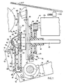
- the typewriter comprises a platen roller 11 and a print unit formed by a carriage 12 which is movable on a cylindrical guide 13 parallel to the roller 11 and on a second guide which is not shown in the drawings.
- the carriage 12 carries a selector device 14 for a character-carrying member 15 or 46 of the disc or 'daisywheel' type, and a print hammer or striker 16.
- the carriage 12 comprises two side members 17 and 18 which are parallel to each other and orthogonal to the axis of the cylindrical guide 13.
- the translatory movement of the carriage 12 in front of the platen roller 11 is controlled in known fashion, for example as described in our published European patent application EP 0 122 039.
- a frame 19 which is disposed between the side members 17 and 18 of the carriage 12 is of such a shape as to have two side members 21 which support a plate 22 parallel to the platen roller 11 and on which are mounted the hammer 16 and the selector device 14.
- the side members 21 of the frame 19 are fixed to two bushes 23 which are mounted coaxially to the cylindrical guide 13 inside the side members 17 and 18 of the carriage 12. In that way the frame 19 is pivoted with respect to the cylindrical guide 13 and follows the movements of the carriage 12 in front of the platen roller 11.
- a single bush 23 and a single side member 21 can be seen in the drawings.
- the frame 19 and the plate 22 can rotate through 16° approximately with respect to the cylindrical guide 13, as described in above-mentioned patent application EP 0 122 039.
- the selector mechanism 14 comprises an electrical dc motor 26 which is capable of rotating in the clockwise and anticlockwise directions.
- the motor 26 has a shaft 27 on which there is fixed a pinion 28,that is always engaged with a toothed wheel 29 mounted on a sleeve 31 on a shaft 33.
- the angular positions of the shaft 33 are detected by a transducer 36 comprising a synchronisation disc 32 fixed on the shaft 33 and provided with a series of transmitting windows 34 disposed adjacent to the circumference thereof, a collimator or an illuminating means 37 and a photodetector 38, which are disposed on opposite sides with respect to the path of movement of the windows 34.
- a transducer 36 comprising a synchronisation disc 32 fixed on the shaft 33 and provided with a series of transmitting windows 34 disposed adjacent to the circumference thereof, a collimator or an illuminating means 37 and a photodetector 38, which are disposed on opposite sides with respect to the path of movement of the windows 34.
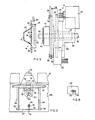
- the shaft 33 is rotatable in a flange 39 (see. Figure 5) of a container 40 which is mounted in such a way that it can be angularly adjusted by means of three screws 53 disposed at 120° to each other, housed in respective slots 54 in the plate 22. Only two screws 53 and two slots 54 can be seen in the drawings. Figure 6 shows a detail of the slots 54 in the plate 22 for the screws 53.
- a sleeve 41 (see Figure 5) is fixed on the shaft 33 and comprises front-mounted coupling means 42 capable of coupling with corresponding coupling means 43 on an adaptor disc 44 mounted on the character-carrying disc 15 or 46.
- the disc 46 is of known type, for example of the type described in Italian patent No 1 016 552 granted to the present applicants on 20th June 1977, and comprises a central hub 45 (see Figure 1) and a hundred radial and flexible spokes or 'petals' 47 which carry a respective print character 48 at their ends.
- a gripping portion 49 having a front wall 51 is fixed to a front surface 52 of the central hub 45.
- the adaptor disc 44 is of known type, for example of the type described in European patent application EP 0 118 277.
- the disc 44 is of plastics material and is of such a configuration as to couple on the one hand with the hub 45 of the character-carrying disc 15 and on the other hand with the sleeve 41. More particularly, the disc 44 comprises two pairs of hooks or catches (not shown in the drawings) which project perpendicularly and which are arranged to engage into respective cavities 56 (see Figure 4) in the character-carrying disc 46 to connect the two discs 44 and 46 together, as described in above-mentioned patent application No 67223-A/83. A cylindrical peg 56 for angular positioning is arranged to co-operate with the hole in the character-carrying disc 46 for angularly positioning the disc 44 and the character-carrying disc 15 or 46 relative to each other.
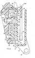
- a seat 58 for receiving a tooth 59.
- the tooth 59 is elastically connected to a frame 60 (see Figure 7) for lifting a correction ribbon 55 which can be lifted by a control element 50 of the type described in European patent application EP 0 118 317 and is part of the arrangement for the zero positioning operation described in European patent application EP 0 119 764.
- a tray member 61 (see Figure 1) of plastics material is disposed substantially vertically between the frame 19 and the platen roller 11.
- the tray member 61 is of substantially parallelepipedic shape, being hollow internally, for housing the character-carrying disc 46.
- the tray member 61 is laterally provided at its bottom with two lugs 62 of which only one is shown in the drawings and which are each pivoted on a pin 63 on the frame 19.
- the tray member 61 further comprises two ribs 64 and 66 (see Figures 1 and 2), each of which has a seat 67 for housing a leg 68 of a lever 69.
- the lever 69 is constantly urged towards the ribs 64 and 66 on the tray member 61 by a spring 71 formed by a steel bar, the ends of which are engaged to two vertical legs 72 of which only one is shown in the drawings and which are disposed at the sides of the tray member 61.
- the lever 69 by means of the end 70 and the element 75, normally bears against the front part 51 of the gripping portion 49 to maintain the coupling between the portions 41 and 42 during the rotary movement of the daisywheel 15.
- the lever 69 is provided with a lower leg 73 - (see Figure 3) housed in a seat in the tray member 61 and an upper leg 76 which is capable of engaging a projection 77 on a plate portion 78, in turn provided with two legs 79 for engaging a vertical plate portion 81 of the lever 69.
- An intermediate support 91 of plastics material has a pin 92 which can be housed in a seat 93 in the lever 69 and supports a photoelectric pair 89 comprising, in side-by-side relationship, an illuminating element 90 and a photosensing element 94, which are housed in a seat or opening 95 in a front wall 100 of the tray member 61.
- the photoelectric arrangement 89 is part of a recognition circuit carried by a printed circuit 96 of which components 97 and 98 have been shown.
- the intermediate support 91 is fixed to the lever 69 by means of an eccentric screw 99 having a nut 101 and a recording sector 102, which permit the photoelectric arrangement 89 to change its angular position with respect to the character-carrying disc 15.
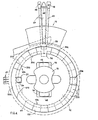
- the electronic typewriter as described hereinbefore may alternatively mount character-carrying daisywheels 46 (see Figure 7) of the type which is already known or daisywheels 15 which are substantially identical to the disc 46 but which are further provided with reflective identification plates 106 (see Figure 4) disposed in a coded fashion in twenty five sectors of a circular ring 109 on the front wall 52.
- the machine further comprises a transparent cover 107 which, when it is closed, protects the region in which the carriage 12 moves in front of the platen roller 11 and which acts on a microswitch 108. Any replacement of the daisywheel 15 or 46 requires the cover 107 first to be opened, and causes the production of a signal COVER by the microswitch 108.
- the position of the photoelectric arrangement 89 (see Figure 3) is regulated by means of the eccentric screw 99.
- a 'specimen' daisywheel (not shown in the drawings) comprising a single petal and a single reflective zone 106 is fitted in position.
- the daisywheel is disposed in front of the arrangement 89, the illuminating element 90 is supplied with a predetermined current and the current at the photosensor element 94 is detected.
- the nut 101 is then slackened and, by means of the registration sector 102, the eccentric screw 99 is rotated.
- the support 91 is thus rotated in a clockwise or anticlockwise direction together with the photoelectric arrangement 89 and the printed circuit 96, thus modifying the relative angular positioning as between the arrangement 89 and the reftective plate.
- the rotary movement as between the arrangement 89 and the 'specimen' daisywheel continues until there is detected at the photosensor 94 a preset current value which conventionally increases in response to an anticlockwise rotation of the support 91, indicating that only the input or leading edge of the plate is aligned with the arrangement 89. That value is intermediate between the maximum value associated with the presence of a reflective plate precisely aligned with the arrangement 89, and the minimum value associated with the absence of reflective plates. When that intermediate value is attained, the nut 101 is locked and the recognition circuit is set.
- the signal at an intermediate value from the element 94 is such as to activate a circuit 109 (see Figure 8) for switching to zero a signal REMAIN that is normally at high logic level.
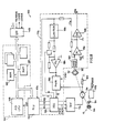
- the motor 26 is servo-controlled by the electron i c circuit 170 of the machine ( Figure 8) comprising a microprocessor 171 with a central unit 168 connected to an input-output unit 169 and a print control unit (PCU) 172.
- the electron i c circuit 170 of the machine Figure 8
- PCU print control unit
- the input-output unit 169 receives and/or transmits signals from the input members of the machine such as the keyboard and other external memory units and receives other signals such as inter alia the signal REMAIN coming from the photosensor 94 and the signal COVER coming from the microswitch 108:
- the unit 172 controls the motor 26 by means of an integrated logic-analog circuit (IC) 173 and a switching-type feeder 174 substantially as described in our European patent application EP 0 102 248 and European application 85307893.9 - (publication EP).
- IC integrated logic-analog circuit
- the feeder 174 feeds the motor 26 with a current whose magnitude depends on the relationship between two pulses of opposite signs, PW1 and PW2 of a frequency which is fixed and high with respect to the activation times of the motor and of variable relative duration.
- the pulses PW1 and PW2 are obtained from a pulse Q of a pulse modulator (PWM) 182, the duration thereof in turn being controlled by a decoder 183 of the circuit 170, in response to the state of three logic signals M1, M2 and M3.
- PWM pulse modulator
- the relationship between PW1 and PW2 is variable in a range of between 0 and 0.5 for a first direction of movement or between 0.5 and 1 for a direction of movement which is opposite to the first, in per se known manner.
- the two ranges are determined by the instantaneous state of the signals M1 and M2.
- the pulse modulator 182 receives feedback signals from the transducer 38 and from the motor 26 and defines the value of the relationship between the signals PW1 and PW2 in the range determined by the signals M1 and M2. For that purpose, the modulator 182 is connected to the photodetector 38 by way of a pre-amplifier 181, an amplifier 184, an amplifier 185 and a dynamic limiter 186, and to the stator circuit of the motor 26 by way of a current sampling resistor 187.
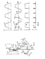
- the fifty transmissive windows 34 in the synchronisation disc 38 are equally spaced from each other. Due to the effect of irradiation by the illuminating means 37 and the rotary movement of the disc 32, the output signal A from the pre-amplifier 181 disposed on the output side of the photodetector 38 is thus trapezoidal.
- the amplifier 184 subtracts from the signal A a reference signal VR and provides a signal FTA (see Figure 9) which is symmetrical with respect to VR, also being trapezoidal, whose amplitude, in the vicinity of the position of alignment of each petal with respect to the hammer, is proportional to the angular displacement of the petal with respect to its position of alignment.
- the signal FTA in response to a clockwise rotation of the character-carrying daisywheel 15 or 46, presents fifty rising edges 188 (see Figure 9) and fifty falling edges 189, so that the period of the signal FTA is double the angular distance between two adjacent petals of the daisywheel 15 or 46.
- the angular spacing between the two edges 188 and 189 is therefore equal to the angular spacing between the axes of three adjacent spokes 47 of the daisywheel 15 or 46.
- the reference voltage VR is also regulated in such a way that two contiguous zero points Xo and X'o of the signal FTA of the two edges 188 and 189 correspond to the angular spacings between the axes of two adjacent petals 47 of the daisywheel 15 or 46.
- the dynamic limiter 186 ( Figure 8) limits the amplitude of the signal FTA at the input to the amplifier 185, to a preset value. Below the maximum value, the signal at each edge 188 is substantially proportional to the angular displacement of each petal at an 'even' position with respect to the position of alignment with the hammer, while the signal of each edge 189 is substantially proportional to the opposite or reverse of the angular displacement of each petal in an odd position.
- the decoder 183 in response to the low state of the signal M3, can produce a signal T which sends the dynamic limiter 186 into a condition of saturation, independently of the value of FTA and, in response to a particular state of the signals M1 and M2, supplies a signal G which modifies the gain of the amplifier 185.
- the values of M1, M2 and M3 are up-dated in response to processing operations internal to the circuit 172 and in response to fresh information received by the microprocessor 171.
- the rising and falling edges of the signal STA in turn represent the moment at which the respectively even and odd petals pass in front of the hammer 16.
- the configuration of the signals M1 and M2 is varied in the varying periods of time between different angular steps, in dependence on the difference in time between the actual time of passage in the preceding period and a theoretical time which is read in a memory ROM 190 of the microprocessor 171.
- the theoretical times in the ROM 190 are preset in dependence on the number of angular steps to be performed and provide acceleration phases and braking phases in order to minimise the total selection time.
- a movement command in accordance with the actual direction of movement of the motor causes acceleration.
- a movement command which is not in accordance with the actual direction of movement causes braking of the motor.
- the motor is subjected to a weak braking action independently of the direction of rotation thereof.
- the signals M1 and M2 are generally variable.
- a first phase of each digital control in the period between two signals INT provides for acceleration or braking substantially as far as half the angular step between two petals and takes account of the difference between the actual time of passage and the theoretical time in the preceding period between two INT and due to a movement which is respectively slower or faster than the theoretical movement. That phase is followed by a short circuit phase until the theoretical time has elapsed.
- the circuit 172 immediately detects that there has been a lag and immediately generates a pair of values M1 and M2 which causes acceleration in advance of the motor, aimed at making up the lag.
- the circuit 172 generates for a fixed time a pair of values M1 and M2 which permit the petal of the desired character to reach an approximate print alignment zone, up to about half a step from the striker.
- the circuit 172 then immediately switches the signal M3 to zero and activates an alignment phase with a particular configuration of the signals M1 and M2.
- the signal M3 0 puts the signal T to zero and the signal FTA can modify the input signal of the pulse modulator 182 by way of the limiter 186 and the amplifier 185 so that the current in the motor 26 is proportional to the angular displacement of the petal from its position of alignment.
- the control of the motor is therefore of analog-positional type.
- the signals STA and FTA are rising in response to a clockwise rotation of the daisywheel and the movement stops at the point Xo in Figure 9.
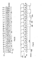
- the plates 106 comprise a phase timing or synchronisation plate 203 (indicated at 1 in Figure 12) which occupies an angular sector which is congruent with that of three character-carrying petals 47, a sector 202 of four petals (indicated at 2 in Figure 12) which is without plates, and a group of other plates 204 (from 3 to 19 in Figure 12) which can occupy selected ones of seventeen contiguous angular sectors 205 of a coded zone and in which each sector 205 is congruent with a sector of four petals 47.
- the remaining portion which corresponds to five sectors of four petals and one sector of five petals is in contrast without plates and defines a non-reflective space (gap) 206 between the synchronisation plate 203 and a last position 207 along the circular ring or array107.
- the sectors of the coded zones, which are left without the reflective plates, outside the gap 206, are in any case fewer than six..
- the photosensor 94 detects the condition of illumination of a part of one of the twenty five sectors in which the plates 106 can be positioned. Alignment with the hammer of the even petals which are not a multiple of four corresponds to alignment with the input or leading edge (for a clockwise rotary movement) of the sector for positioning of the plates 106. Under those conditions, for.
- the signal REMAIN will be of an ambiguous value dependent on the phase displacement of the plates with respect to the theoretical position, for the petals at even positions which are not a.multiple of four (indicated at 214 in Figure 11).
- Fig 11 is drawn for the case in which the first few sectors 205 are alternatively with and without plates.
- the seventeen coded positions define thirteen bits which form an identification code and four bits which form a reference control code.
- the plates of the identification code are subdivided into three groups of which a first group 208 of three bits (A, B, C) ( Figure 12) represents the spacing pitch of the characters 58 (for example 1/10", 1/12", 1/15", P5), a second group 205 of three bits (A, B, C) represents the mean dimensions of the characters and influences the mean strength of striking, and a third group 210 of seven bits (A, B, C, D, E, F, G) is indicative of the linguistic grouping to which the daisywheel belongs.
- the initialisation phase indicated at 219 in Figure 10 follows a state of zeroing of the memories RAMs 191 of the microprocessor 172.
- the ROMs 190 of the microprocessor 171 comprise locations intended for a program which produces the initialisation phase in accordance with the following steps:
- the program continues to rotate the daisywheel until a timer - (junction 225) signals that the time intended for that phase has elapsed; in that case the program proceeds to start a mechanical zeroing cycle 226 which will be described hereinafter.
- the program proceeds to activate the mechanical initialisation cycle 226.
- the program transfers the codes read into the RAM 191 (block 233) and proceeds with a rotary movement of four petals in an anticlockwise direction (block 234) to a position of alignment of the petal with the underlining character U. zero position, in front of the striker.
- the program (block 235) resets the registers of the RAMs 191 which are representative of the angular position of the daisywheel.
- the structure of the reflective plates as defined hereinbefore, in combination with correct positioning of the synchronisation disc 32 permits the daisywheel to be put into its zero position, even if the plates are displaced from their theoretical position by an angle of up to more or less half the angular step or pitch of the petals 47. That function is carried out by the dimension of the plate 203 which is reduced in comparison with that of the other plates 106.
- the program proceeds to read REMAIN only as a consequence of incremental rotary movements of two petals in correspondence with the petals at even positions.
- the count will be equal to nineteen.
- Reading of the plate 207 is thus reliable even if the plate were displaced in a clockwise direction as far as almost one petal and as far as two petals in an anticlockwise direction.
- the subsequent operation of reading the other plates is effected by incremental rotary movements equal to four petals.
- the operation of reading the other plates thus occurs at the respective central zones and permits a positioning tolerance equal to almost two petals in the two directions of rotation.
- Figure 11 puts in phase relationship the state of the signal STA and the signal REMAIN, with the reading operations in respect of the logic blocks 221 and 222 in Figure 10 and associated respectively with the petals in even positions and the petals in positions which are a multiple of four.
- the reflective synchronisation plate could also be of a width which is equal to that of the other plates.
- all the plates would therefore have to be displaced by a petal with respect to the position in the first embodiment.
- Identification of the synchronisation plate would be effected in a similar manner to that described hereinbefore.
- the subsequent operation of reading the code will therefore take place every four petals, corresponding to the petals at odd positions, after a jump of five petals. In that case, tolerance in regard to positioning of the plates would be limited to a single petal both in regard to the synchronisation plates and in regard to the coded plates.
- control code in the zone 211 finally ensures that any accidental event which modifies the state of the signal REMAIN with respect to its theoretical value cannot introduce wrong information regarding the daisywheels which are actually used in the print unit of the typewriter.
- the program activates the mechanical initialisation cycle 226 which is similar to that described in our above-mentioned patent application EP 0 119 764.
- the initialisation cycle 226 follows the stop- ' page of the daisywheel 15 or 46 at a point Xo of the synchronisation disc 32 (block 220) and provides (block 240) for lifting of the correction ribbon 55 and resilient contact of the tooth 59 against the cylindrical surface of the adaptor disc 44..
- the program then provides a command for rotary movement in the anticlockwise direction equal to two petals (block 241). If the tooth 59 has not entered the recess 58, the rotary movement of the daisywheel may take place freely, and the program detects the start of two edges of the signal STA (junction 242) and activates a positional-type stop command (block 243). The same occurs if a time greater than that provided for that phase (junction 243) has elapsed.
- the program proceeds with a programmed rotary movement at low speed and in a clockwise direction without time control for 101 annular increments (block 244).
- the program then continues with lowering of the corrector ribbon 55 (block 248) and consequential disengagement. of the tooth 59 from the recess 58 and with zeroing of the registers of the RAMs 191 (block 233), either in the case of recognition of the one hundred edges of the signal STA (junction 245 and junction 246), indicative either that it is already in the zero position and that there has been rebounding or bouncing as between the tooth 59 and the recess 58, or in the case where the daisywheel has stopped, edges of the signal STA have not occurred and the timer has detected the elapsing of a period of time greater that that provided for.
Landscapes
- Character Spaces And Line Spaces In Printers (AREA)
Applications Claiming Priority (2)
| Application Number | Priority Date | Filing Date | Title |
|---|---|---|---|
| IT6737585 | 1985-04-22 | ||
| IT67375/85A IT1199878B (it) | 1985-04-22 | 1985-04-22 | Organo portacaratteri girevole e suo dispositivo di selezione per un unita di stampa di macchine scriventi |
Publications (3)
| Publication Number | Publication Date |
|---|---|
| EP0200439A2 true EP0200439A2 (de) | 1986-11-05 |
| EP0200439A3 EP0200439A3 (en) | 1987-09-30 |
| EP0200439B1 EP0200439B1 (de) | 1991-06-19 |
Family
ID=11301871
Family Applications (1)
| Application Number | Title | Priority Date | Filing Date |
|---|---|---|---|
| EP86302946A Expired - Lifetime EP0200439B1 (de) | 1985-04-22 | 1986-04-18 | Drehbarer Typenträger und Auswahlvorrichtung für eine Druckeinheit in Schreibmaschinen |
Country Status (5)
| Country | Link |
|---|---|
| US (1) | US4778289A (de) |
| EP (1) | EP0200439B1 (de) |
| JP (1) | JPS61258772A (de) |
| DE (1) | DE3679859D1 (de) |
| IT (1) | IT1199878B (de) |
Cited By (1)
| Publication number | Priority date | Publication date | Assignee | Title |
|---|---|---|---|---|
| US4865475A (en) * | 1987-01-07 | 1989-09-12 | Brother Kogyo Kabushiki Kaisha | Printer adjusting the print hammer position for precise printing |
Families Citing this family (2)
| Publication number | Priority date | Publication date | Assignee | Title |
|---|---|---|---|---|
| JPH0544538U (ja) * | 1991-11-20 | 1993-06-15 | ブラザー工業株式会社 | 印字装置 |
| JP2014156062A (ja) * | 2013-02-15 | 2014-08-28 | Seiko Epson Corp | 記録装置 |
Family Cites Families (14)
| Publication number | Priority date | Publication date | Assignee | Title |
|---|---|---|---|---|
| CA1039217A (en) * | 1974-07-01 | 1978-09-26 | Willy J. Grundherr | Rotary wheel printing system |
| GB1604577A (en) * | 1977-09-14 | 1981-12-09 | Exxon Research Engineering Co | Coded printing element and apparatus for use thereof |
| GB1604578A (en) * | 1977-09-14 | 1981-12-09 | Exxon Research Engineering Co | Method and apparatus for sensing the position of a printing element |
| US4219766A (en) * | 1978-03-27 | 1980-08-26 | Qume Corporation | Hybrid dual mode servo-system |
| US4281938A (en) * | 1980-01-14 | 1981-08-04 | Phillips Stephen R | Automatic print wheel element changing mechanism for a serial printer |
| US4338035A (en) * | 1980-08-11 | 1982-07-06 | Canon Kabushiki Kaisha | Printer |
| JPS57100084A (en) * | 1980-12-16 | 1982-06-22 | Ricoh Co Ltd | Self-indentifying device for type wheel |
| IT1156505B (it) * | 1982-09-01 | 1987-02-04 | Olivetti & Co Spa | Dispositivo per controllare la velocita ed il posizionamento di un motore elettrico |
| IT1165548B (it) * | 1983-02-22 | 1987-04-22 | Olivetti & Co Spa | Macchina per scrivere elettronica con dispositivo per il posizionamento di zero di un organo portacaratteri girevole |
| IT1158811B (it) * | 1983-02-28 | 1987-02-25 | Olivetti & Co Spa | Dispositivo per accoppiare un disco portacaratteri ad un motore di selezione |
| IT1159366B (it) * | 1983-03-10 | 1987-02-25 | Olivetti & Co Spa | Dispositivo per montare un disco portacaratteri in una macchina per scrivere |
| JPS59179351A (ja) * | 1983-03-31 | 1984-10-11 | Ricoh Co Ltd | プリンタ |
| JPS59209895A (ja) * | 1983-05-16 | 1984-11-28 | Ricoh Co Ltd | 印字位置制御方式 |
| IT1180106B (it) * | 1984-11-05 | 1987-09-23 | Olivetti & Co Spa | Circuito per il pilotaggio dei motori elettrici di selezione tabulazione ed interlinea di una macchina per scrivere elettronica |
-
1985
- 1985-04-22 IT IT67375/85A patent/IT1199878B/it active
-
1986
- 1986-04-18 DE DE8686302946T patent/DE3679859D1/de not_active Expired - Lifetime
- 1986-04-18 EP EP86302946A patent/EP0200439B1/de not_active Expired - Lifetime
- 1986-04-22 JP JP61093169A patent/JPS61258772A/ja active Pending
- 1986-04-30 US US06/857,348 patent/US4778289A/en not_active Expired - Fee Related
Cited By (1)
| Publication number | Priority date | Publication date | Assignee | Title |
|---|---|---|---|---|
| US4865475A (en) * | 1987-01-07 | 1989-09-12 | Brother Kogyo Kabushiki Kaisha | Printer adjusting the print hammer position for precise printing |
Also Published As
| Publication number | Publication date |
|---|---|
| DE3679859D1 (de) | 1991-07-25 |
| IT8567375A1 (it) | 1986-10-22 |
| EP0200439B1 (de) | 1991-06-19 |
| IT1199878B (it) | 1989-01-05 |
| JPS61258772A (ja) | 1986-11-17 |
| IT8567375A0 (it) | 1985-04-22 |
| US4778289A (en) | 1988-10-18 |
| EP0200439A3 (en) | 1987-09-30 |
Similar Documents
| Publication | Publication Date | Title |
|---|---|---|
| US4118129A (en) | Rotary wheel printing system | |
| US4091913A (en) | Printing apparatus with printing material non-motion detector | |
| US4103766A (en) | Control apparatus for serial printer | |
| US4195938A (en) | Lateral position control means for data printer heads | |
| US4216415A (en) | Position control system comprising a digital algebraic adder circuit | |
| EP0139937B1 (de) | Gerät zur Initialisierung eines Gänseblümchenraddruckers | |
| US4390293A (en) | Electronic typewriter | |
| JPS6330966Y2 (de) | ||
| US5021781A (en) | Two stage quadrature incremental encoder | |
| CA1096802A (en) | Coded printing element and apparatus for use thereof | |
| US4058195A (en) | Increment-decrement logic for serial printer | |
| US4428694A (en) | Rotary printing device with identifying means and method and apparatus for in situ identification | |
| EP0200439A2 (de) | Drehbarer Typenträger und Auswahlvorrichtung für eine Druckeinheit in Schreibmaschinen | |
| US4897589A (en) | Apparatus for indexing an origin of a moving member | |
| US4504158A (en) | Positioning device for a selection member of printing machines | |
| US4037208A (en) | Hammer intensity selection apparatus for serial printer | |
| US4037216A (en) | Position retry apparatus for serial printer | |
| US4398837A (en) | Printing apparatus and method for preventing printing errors in same | |
| US4035781A (en) | Signal priority logic for serial printer | |
| EP0043733B1 (de) | Vorrichtung zum Steuern der Bewegung eines beweglichen Elements | |
| US4575269A (en) | Portable electronic typewriter | |
| US5005995A (en) | Method of automatically identifying a print wheel | |
| WO1981002347A1 (en) | Position control methods and systems | |
| CA1057204A (en) | Rotary wheel printer with variable intensity imprint | |
| GB1604578A (en) | Method and apparatus for sensing the position of a printing element |
Legal Events
| Date | Code | Title | Description |
|---|---|---|---|
| PUAI | Public reference made under article 153(3) epc to a published international application that has entered the european phase |
Free format text: ORIGINAL CODE: 0009012 |
|
| AK | Designated contracting states |
Kind code of ref document: A2 Designated state(s): DE FR GB |
|
| PUAB | Information related to the publication of an a document modified or deleted |
Free format text: ORIGINAL CODE: 0009199EPPU |
|
| RA1 | Application published (corrected) |
Date of ref document: 19861210 Kind code of ref document: A2 |
|
| PUAL | Search report despatched |
Free format text: ORIGINAL CODE: 0009013 |
|
| RHK1 | Main classification (correction) |
Ipc: B41J 1/30 |
|
| AK | Designated contracting states |
Kind code of ref document: A3 Designated state(s): DE FR GB |
|
| 17P | Request for examination filed |
Effective date: 19880307 |
|
| 17Q | First examination report despatched |
Effective date: 19890629 |
|
| GRAA | (expected) grant |
Free format text: ORIGINAL CODE: 0009210 |
|
| AK | Designated contracting states |
Kind code of ref document: B1 Designated state(s): DE FR GB |
|
| REF | Corresponds to: |
Ref document number: 3679859 Country of ref document: DE Date of ref document: 19910725 |
|
| ET | Fr: translation filed | ||
| PLBE | No opposition filed within time limit |
Free format text: ORIGINAL CODE: 0009261 |
|
| STAA | Information on the status of an ep patent application or granted ep patent |
Free format text: STATUS: NO OPPOSITION FILED WITHIN TIME LIMIT |
|
| 26N | No opposition filed | ||
| PGFP | Annual fee paid to national office [announced via postgrant information from national office to epo] |
Ref country code: GB Payment date: 19970409 Year of fee payment: 12 Ref country code: FR Payment date: 19970409 Year of fee payment: 12 |
|
| PGFP | Annual fee paid to national office [announced via postgrant information from national office to epo] |
Ref country code: DE Payment date: 19970428 Year of fee payment: 12 |
|
| PG25 | Lapsed in a contracting state [announced via postgrant information from national office to epo] |
Ref country code: GB Free format text: LAPSE BECAUSE OF NON-PAYMENT OF DUE FEES Effective date: 19980418 |
|
| PG25 | Lapsed in a contracting state [announced via postgrant information from national office to epo] |
Ref country code: FR Free format text: THE PATENT HAS BEEN ANNULLED BY A DECISION OF A NATIONAL AUTHORITY Effective date: 19980430 |
|
| GBPC | Gb: european patent ceased through non-payment of renewal fee |
Effective date: 19980418 |
|
| PG25 | Lapsed in a contracting state [announced via postgrant information from national office to epo] |
Ref country code: DE Free format text: LAPSE BECAUSE OF NON-PAYMENT OF DUE FEES Effective date: 19990202 |
|
| REG | Reference to a national code |
Ref country code: FR Ref legal event code: ST |