EP0200374B1 - Übersichtsaufnahmen - Google Patents
Übersichtsaufnahmen Download PDFInfo
- Publication number
- EP0200374B1 EP0200374B1 EP86302428A EP86302428A EP0200374B1 EP 0200374 B1 EP0200374 B1 EP 0200374B1 EP 86302428 A EP86302428 A EP 86302428A EP 86302428 A EP86302428 A EP 86302428A EP 0200374 B1 EP0200374 B1 EP 0200374B1
- Authority
- EP
- European Patent Office
- Prior art keywords
- array
- source
- subject
- movements
- radiation
- Prior art date
- Legal status (The legal status is an assumption and is not a legal conclusion. Google has not performed a legal analysis and makes no representation as to the accuracy of the status listed.)
- Expired
Links
- 238000003384 imaging method Methods 0.000 title description 2
- 230000005855 radiation Effects 0.000 claims description 33
- 238000000034 method Methods 0.000 claims description 23
- 238000002591 computed tomography Methods 0.000 claims description 21
- 230000004807 localization Effects 0.000 description 4
- 238000013507 mapping Methods 0.000 description 4
- NJPPVKZQTLUDBO-UHFFFAOYSA-N novaluron Chemical compound C1=C(Cl)C(OC(F)(F)C(OC(F)(F)F)F)=CC=C1NC(=O)NC(=O)C1=C(F)C=CC=C1F NJPPVKZQTLUDBO-UHFFFAOYSA-N 0.000 description 3
- 238000003491 array Methods 0.000 description 2
- 230000015572 biosynthetic process Effects 0.000 description 2
- 238000013480 data collection Methods 0.000 description 2
- 210000000056 organ Anatomy 0.000 description 2
- 241000711981 Sais Species 0.000 description 1
- 230000017531 blood circulation Effects 0.000 description 1
- 210000004204 blood vessel Anatomy 0.000 description 1
- 239000002872 contrast media Substances 0.000 description 1
- 238000002347 injection Methods 0.000 description 1
- 239000007924 injection Substances 0.000 description 1
- 238000000926 separation method Methods 0.000 description 1
- 239000007787 solid Substances 0.000 description 1
Images

Classifications
-
- A—HUMAN NECESSITIES
- A61—MEDICAL OR VETERINARY SCIENCE; HYGIENE
- A61B—DIAGNOSIS; SURGERY; IDENTIFICATION
- A61B6/00—Apparatus or devices for radiation diagnosis; Apparatus or devices for radiation diagnosis combined with radiation therapy equipment
- A61B6/02—Arrangements for diagnosis sequentially in different planes; Stereoscopic radiation diagnosis
- A61B6/03—Computed tomography [CT]
- A61B6/032—Transmission computed tomography [CT]
-
- A—HUMAN NECESSITIES
- A61—MEDICAL OR VETERINARY SCIENCE; HYGIENE
- A61B—DIAGNOSIS; SURGERY; IDENTIFICATION
- A61B6/00—Apparatus or devices for radiation diagnosis; Apparatus or devices for radiation diagnosis combined with radiation therapy equipment
- A61B6/04—Positioning of patients; Tiltable beds or the like
- A61B6/0487—Motor-assisted positioning
-
- A—HUMAN NECESSITIES
- A61—MEDICAL OR VETERINARY SCIENCE; HYGIENE
- A61B—DIAGNOSIS; SURGERY; IDENTIFICATION
- A61B6/00—Apparatus or devices for radiation diagnosis; Apparatus or devices for radiation diagnosis combined with radiation therapy equipment
- A61B6/42—Arrangements for detecting radiation specially adapted for radiation diagnosis
- A61B6/4275—Arrangements for detecting radiation specially adapted for radiation diagnosis using a detector unit almost surrounding the patient, e.g. more than 180°
-
- Y—GENERAL TAGGING OF NEW TECHNOLOGICAL DEVELOPMENTS; GENERAL TAGGING OF CROSS-SECTIONAL TECHNOLOGIES SPANNING OVER SEVERAL SECTIONS OF THE IPC; TECHNICAL SUBJECTS COVERED BY FORMER USPC CROSS-REFERENCE ART COLLECTIONS [XRACs] AND DIGESTS
- Y10—TECHNICAL SUBJECTS COVERED BY FORMER USPC
- Y10S—TECHNICAL SUBJECTS COVERED BY FORMER USPC CROSS-REFERENCE ART COLLECTIONS [XRACs] AND DIGESTS
- Y10S378/00—X-ray or gamma ray systems or devices
- Y10S378/901—Computer tomography program or processor
Definitions
- This invention relates to methods and apparatus for use in obtaining shadowgraph images and more especially to such methods and apparatus for use in locating a tomographic plane to be scanned using a computed tomography (CT) apparatus.
- CT computed tomography
- CT computed tomography
- a subject is irradiated from a number of directions and the intensity of radiation passing through the subject is detected.
- This procedure provides information sufficient to generate a cross-sectional mapping of attenuation within the subject.
- the procedure for generating this mapping is known within the computed tomography art as filtered back projection.
- Various methods of reconstruction imaging have been developed as the computer tomography art has matured. In most all, if not all, commercial CT scanners presently known to applicants, x-ray attenuation data are fourier transformed, filtered, and then retransformed prior to back projection.
- Computed tomography scanners have evolved in stages.
- An initial scanner used a single x-ray source and single detector which traversed back and forth in unison obtaining intensity information for use in the back projection process.
- Second and third generation scanners employed detector arrays rather than individual detectors. In second generation scanners these arrays traversed and orbited while in third generation they simply orbit with the x-ray source.
- a fourth generation scanner employs a circular array of detectors circumscribing a subject region of interest. The x-ray source orbits with respect to this circular detector array to irradiate the subject from a plurality of positions.
- the detector array includes 1200 closely spaced detectors forming a circle whose diameter is greater than the diameter of the circular path followed by the x-ray tube as it orbits the patient. Stated another way, x-radiation from the tube travels a shorter distance between tube and patient than between the patient and detector array after traversing the patient.
- computed tomography scanners One requirement of computed tomography scanners is a procedure for accurately positioning the subject prior to conducting a computed tomography scan. For example, if a diagnosing physician is interested in viewing the internal structure of a particular organ, it is inefficient and undesirable to scan the entire body. Instead, only a region of interest including the organ or other body part of concern is scanned.
- the x-ray source can be locked in a stationary position relative to the detector array and the subject moved past the array as the source irradiates the subject.
- X-ray intensity data from a group of detectors is sensed sequentially at each of a series of data collection positions. At each data collection position a new row of intensity information is gathered.
- an image similar to a conventional digital x-ray shadowgraph image is created. Such an image does not represent a cross-sectional image but instead, depicts the transmissivity of the subject along paths from the fixed x-ray source to individual elements of the detector array. While not providing the resolution and/or information of a computed tomography scan, such a localization scan can be used to locate structure within the subject in anticipation of positioning that subject for a complete CT scan.
- EP-A 10 041 752 Such a localization scan is described in EP-A 10 041 752.
- EP-A 10 041 752 there is further described a method comprising carrying out localization scans to obtain two sets of shadowgraph image data, which differ only in respect of an image determining parameter and substracting one from the other.
- the difference in an image determining parameter may, for example, be due to the injection of a contrast medium into the blood flow in a subject so that the difference image reveals the location of blood vessels in the subject.
- EP-A 10 041 752 also describes the formation of a pair of shadowgraph images to provide a stereoscopic view of a subject, and the formation of a series of shadowgraph images for kinemato- graphic presentation.
- the invention provides a method of obtaining shadowgraph image data relating to a subject wherein: radiation from a radiation source is directed through the subject to an array of radiation detectors; and data is obtained representing the radiation reaching said array through said subject as said subject is moved relative to said source and said array orthogonally to the radiation path; data being obtained during two corresponding movements of said subject relative to said source and said array; and said data for the two movements being combined to produce said image data; characterised in that the said radiation is directed along trajectories through said subject during one said movement which are different from the trajectories during the other said movement; and said data for the two movements are combined in an array by interleaving said data so as to provide image data of greater resolution than that given by the data for either one movement alone.
- the invention also provides an apparatus for producing a shadowgraph image of a subject comprising: a radiation source; an array of radiation detectors; means positioning said source and array so as to direct radiation through said subject onto said array; means for moving said subject orthogonally to the radiation path and relative to said source and said array; means for producing signals representing the radiation reaching said array from the source through said subject as said subject is moved relative to said source and said array; and means for utilising said signals to construct said image; said means for moving comprising means for carrying out two corresponding movements of said subject relative to said source and said array; and said means for utilising combining the said signals produced during both said movements; characterised in that said means for positioning includes means for moving said source relative to said subject and said array between sais movements so that the said radiation is directed along trajectories through said subject during one said movement which are different from the trajectories during the other said movement; and said means for utilising combines the signals produced during said two movements in an array by interleaving said data so as to construct an image of greater resolution than that given by the signals
- said source and detector array may be the source and detector array of a CT scaner apparatus.
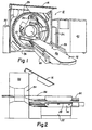
- the scanner 10 is illustrated with a front panel 14 pivoted away from its in use position to show the internal components of the scanner 10.
- the scanner 10 includes a rotatable x-ray source 20 mounted on a rotatable frame 22.
- the frame 22 is journalled for rotation within a gantry 24.
- Coupled to and supported by the gantry 24 are a plurality of x-radiation detectors forming a detector array 28.
- radiation from the source 20 passes across a patient aperture 30 in a plane 32 to the detector array 28.
- the x-ray source 20 is rotated by a motor (not shown) in a circular orbit around a patient aperture 30.
- a generally planar and spread beam of radiation from the source 20 impinges upon a group of detectors forming a part of the detector array 28.
- different detectors are irradiated and intensity information obtained from these detectors.
- Output signals from the detector array 28 are processed by components that convert the radiation into visible light, to an analog electric signal, to a frequency, and then to digital attenuation values.
- a computer 40 stores this data derived from these values and uses it for reconstruction processing.
- the patient couch 12 includes a base 52 supporting a movable frame 54 which supports a top 56.
- top 56 and frame 54 are bounded on either side by retractable handles 58 and an arm rest 60.
- a frame lift motor (not shown) raises the frame 54, top 56 and handles 58 from the position shown in solid in Figure 2 to the position shown in phantom. In this raised position, the patient can be moved into and out of the patient aperture 30.
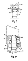
- a longitudinal drive mechanism for the couch frame 54 and top 56 is seen in Figure 5.
- One of two pedestal supports 62 is shown supporting the frame 54.
- This support 62 is coupled to a second pedestal (not shown) by a shaft and rack and pinion drive so that the two pedestal supports move in unison as the frame is raised and lowered.
- a motor driven screw jack 74 is coupled to a mounting block 75 which engages a bottom surface 54b of the frame 54.
- a D.C. motor 50 mounted within the frame 54.
- a drive pulley 82 mounted to a motor drive shaft is rotated in either of two directions.
- a pulley 84 ( Figure 4) mounted to a shaft 85 journaled in the frame 54 is connected to the drive pulley 82 by a belt 87 and rotates in response to energization of the motor 50.
- a gear 86 mounted on the shaft 85 engages an elongated gear belt 88 coupled to the movable top 56 so that rotation of the gear 86 exerts a force on the moveable top 56. Controlled energization of the motor 50 drives the gear belt and attached top 56 into and out of the aperture 30.
- the top 56 and frame 54 coact along two bearing rails 90 (only one of which is seen in Figure 3A). Each rail is mounted on a shaft support block 92 (one of which is shown in Figure 3A). The rails 90 each engage bearings 93 running the length of the moveable top 56. Directly beneath the rail 90 ( Figure 3A) are side rails 94 which support the arm rests 60 ( Figure 3).
- the patient couch 12 is motorized so that a patient placed on the couch can be moved into the scanner aperture 30.
- the patient is moved into the aperture 30 so that radiation from the tube 20 passes through the patient cross-section 32 ( Figure 2).
- a shadowgraph patient image is obtained.
- the x-ray tube 20 is fixed with respect to the gantry 24 and a beam of x-radiation is directed through the patient to a segment of adjacent detectors of the detector array 28.
- the x-ray tube 20 remains energized as the motor 50 continuously moves the patient axially of the aperutre 30 and through the beam of radiation.
- X-radiation data from the energized x-ray detector segment is sensed and stored for the time period in which the patient is driven with respect to the scanner through a first longitudinal scan. During this first scan, movement of the top 56 is co-ordinated with radiation attentuation sensing so the data stored in the computer is organized in a rectangular array of pixels of attenuation data.
- the radiation output from 128 adjacent detectors is sampled every millimeter at 128 different patient/scanner positons to obtain a 128 by 128 pixel shadowgraph data set.
- the source 20 is orbitally indexed a small amount to provide a second shadowgraph data set.
- the source is moved .3 degrees from its original position.
- the motor 50 is then energized to reverse the longitudinal scanning direction.
- the top 56 then moves in an opposite direction as a second set of shadowgraph data is obtained.
- the pixel data for each of the two shadowgraph images is then interleaved by the computer 40 to obtain a resultant shadowgraph of 256 by 128 pixels having twice the data set resolution of either individual longitudinal scan.
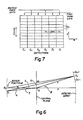
- a grid like mapping ( Figure 7) of data from the 128 detectors is created. Along the longitudinal direction the center-to-center spacing between adjacent data regions is 1 mm. Without multiple scans the detector spacing is approximately 4 mm but with the interleaving of data from two scans with the source orbited between scans the separation between data regions is about 2 mm.
- FIG. 6 a geometric examination of shadowgraph data interleaving is presented.
- two source positions S1 and S2 are seen in relation to a detector array having representative detectors Dn, Dn+1, and Dn-1.
- the angle y represents the angle by which the scanning frame is rotated between longitudinal scans.
- Depicted in a central scanning plane are two points Xi, X 2 .
- the following two equations represent the distance of these points Xi, X 2 from the origin O as a function of the Figure 6 parameters.
Landscapes
- Health & Medical Sciences (AREA)
- Life Sciences & Earth Sciences (AREA)
- Engineering & Computer Science (AREA)
- Medical Informatics (AREA)
- Radiology & Medical Imaging (AREA)
- Molecular Biology (AREA)
- Biophysics (AREA)
- Nuclear Medicine, Radiotherapy & Molecular Imaging (AREA)
- Optics & Photonics (AREA)
- Pathology (AREA)
- Physics & Mathematics (AREA)
- Biomedical Technology (AREA)
- Heart & Thoracic Surgery (AREA)
- High Energy & Nuclear Physics (AREA)
- Surgery (AREA)
- Animal Behavior & Ethology (AREA)
- General Health & Medical Sciences (AREA)
- Public Health (AREA)
- Veterinary Medicine (AREA)
- Pulmonology (AREA)
- Theoretical Computer Science (AREA)
- Apparatus For Radiation Diagnosis (AREA)
- Analysing Materials By The Use Of Radiation (AREA)
Claims (15)
Applications Claiming Priority (2)
| Application Number | Priority Date | Filing Date | Title |
|---|---|---|---|
| US722672 | 1985-04-12 | ||
| US06/722,672 US4686692A (en) | 1985-04-12 | 1985-04-12 | Computed tomography patient localization scanning |
Publications (3)
| Publication Number | Publication Date |
|---|---|
| EP0200374A2 EP0200374A2 (de) | 1986-11-05 |
| EP0200374A3 EP0200374A3 (en) | 1987-05-27 |
| EP0200374B1 true EP0200374B1 (de) | 1989-08-09 |
Family
ID=24902871
Family Applications (1)
| Application Number | Title | Priority Date | Filing Date |
|---|---|---|---|
| EP86302428A Expired EP0200374B1 (de) | 1985-04-12 | 1986-04-02 | Übersichtsaufnahmen |
Country Status (5)
| Country | Link |
|---|---|
| US (1) | US4686692A (de) |
| EP (1) | EP0200374B1 (de) |
| JP (1) | JPH0724658B2 (de) |
| CA (1) | CA1236594A (de) |
| DE (1) | DE3664863D1 (de) |
Families Citing this family (12)
| Publication number | Priority date | Publication date | Assignee | Title |
|---|---|---|---|---|
| FR2601579A1 (fr) * | 1986-07-18 | 1988-01-22 | Thomson Cgr | Lit d'examen, notamment pour appareil de rmn ou de tomodensitometrie. |
| US5199123A (en) * | 1986-07-18 | 1993-04-06 | General Electric Cgr Sa | Examination bed for NMR or tomodensitometry apparatus |
| FR2601580A1 (fr) * | 1986-07-18 | 1988-01-22 | Thomson Cgr | Lit medical d'examen, notamment pour appareil de rmn ou de tomodensitometrie. |
| US4894778A (en) * | 1988-09-16 | 1990-01-16 | Yokogawa Medical Systems, Limited | X-ray computerized tomographic device |
| US4965726A (en) * | 1988-10-20 | 1990-10-23 | Picker International, Inc. | CT scanner with segmented detector array |
| JPH0368343A (ja) * | 1989-08-09 | 1991-03-25 | Toshiba Corp | 医用寝台装置 |
| US6493571B1 (en) | 1997-04-11 | 2002-12-10 | William Beaumont Hospital | Rapid magnetic resonance imaging and magnetic resonance angiography of multiple anatomical territories |
| US6507631B1 (en) * | 1999-12-22 | 2003-01-14 | Tetsuo Takuno | X-ray three-dimensional imaging method and apparatus |
| FR2812807B1 (fr) * | 2000-08-08 | 2002-11-15 | Alm | Table d'operation, destinee notamment a des interventions chirurgicales |
| US7403811B2 (en) * | 2004-03-01 | 2008-07-22 | Scimed Life Systems, Inc. | Method of catheter tracking using image information |
| DE102010027227B4 (de) * | 2010-07-15 | 2016-10-20 | Siemens Healthcare Gmbh | Verfahren und Computertomographiegerät zur Durchführung einer angiographischen Untersuchung |
| CN103499593A (zh) * | 2013-09-23 | 2014-01-08 | 深圳先进技术研究院 | 一种计算机断层扫描系统 |
Family Cites Families (14)
| Publication number | Priority date | Publication date | Assignee | Title |
|---|---|---|---|---|
| US3745245A (en) * | 1970-06-16 | 1973-07-10 | Hitachi Roentgen | High resolution system for t.v. monitoring of intermittant x-ray signals |
| US4048505A (en) * | 1974-07-17 | 1977-09-13 | E M I Limited | Radiography |
| US3983399A (en) * | 1975-03-18 | 1976-09-28 | Picker Corporation | Tomography system having axial scanning |
| US4123657A (en) * | 1975-11-28 | 1978-10-31 | Artronix Inc. | X-ray detector |
| DE2613809B2 (de) * | 1976-03-31 | 1979-01-04 | Siemens Ag, 1000 Berlin Und 8000 Muenchen | Röntgenschichtgerät zur Herstellung von Transversal-Schichtbildern |
| US4179100A (en) * | 1977-08-01 | 1979-12-18 | University Of Pittsburgh | Radiography apparatus |
| EP0010885B1 (de) * | 1978-10-24 | 1983-02-23 | EMI Limited | Gerät für Computer-Tomographie |
| DE3018541A1 (de) * | 1980-05-14 | 1981-11-19 | Siemens AG, 1000 Berlin und 8000 München | Roentgenstereoeinrichtung |
| NL8003354A (nl) * | 1980-06-09 | 1982-01-04 | Philips Nv | Stralingsonderzoekapparaat met beeldsubtractie. |
| JPS57195444A (en) * | 1981-05-26 | 1982-12-01 | Tokyo Shibaura Electric Co | X-ray photographing apparatus |
| US4392096A (en) * | 1981-10-15 | 1983-07-05 | General Electric Company | Sectional X-ray table having dual servo drives |
| DE3148507A1 (de) * | 1981-12-08 | 1983-06-16 | Siemens AG, 1000 Berlin und 8000 München | Roentgendiagnostikanlage fuer angiographische roentgenuntersuchungen |
| DE3227625A1 (de) * | 1982-07-23 | 1984-01-26 | Siemens AG, 1000 Berlin und 8000 München | Computertomograph |
| JPS59155238A (ja) * | 1983-02-24 | 1984-09-04 | 株式会社東芝 | X線ct装置 |
-
1985
- 1985-04-12 US US06/722,672 patent/US4686692A/en not_active Expired - Lifetime
-
1986
- 1986-02-10 CA CA000501486A patent/CA1236594A/en not_active Expired
- 1986-04-02 DE DE8686302428T patent/DE3664863D1/de not_active Expired
- 1986-04-02 EP EP86302428A patent/EP0200374B1/de not_active Expired
- 1986-04-11 JP JP61083977A patent/JPH0724658B2/ja not_active Expired - Lifetime
Also Published As
| Publication number | Publication date |
|---|---|
| DE3664863D1 (en) | 1989-09-14 |
| EP0200374A3 (en) | 1987-05-27 |
| CA1236594A (en) | 1988-05-10 |
| JPH0724658B2 (ja) | 1995-03-22 |
| EP0200374A2 (de) | 1986-11-05 |
| JPS61240944A (ja) | 1986-10-27 |
| US4686692A (en) | 1987-08-11 |
Similar Documents
| Publication | Publication Date | Title |
|---|---|---|
| US6574296B2 (en) | Computer tomography unit and method for operating same | |
| US6421412B1 (en) | Dual cardiac CT scanner | |
| US6639965B1 (en) | Methods and apparatus for cardiac imaging with conventional computed tomography | |
| US6470066B2 (en) | X-ray computerized tomography apparatus, control method therefor and image generating method using the apparatus | |
| EP0113879B1 (de) | Rechnergesteuerter Tomograph mit Strahlenquelle | |
| US4736396A (en) | Tomosynthesis using high speed CT scanning system | |
| EP1605826B1 (de) | Computertomographisches bildgebungssystem | |
| EP1324699B1 (de) | Spiralabtastrekonstruktion des herzens für tomograph mit zweidimensionaler detektoranordung | |
| CN1130498A (zh) | 计算机层析x射线摄影仪 | |
| EP0200374B1 (de) | Übersichtsaufnahmen | |
| US6408042B1 (en) | Methods and apparatus for cone beam artifact suppression in scanning imaging systems | |
| JP2002095655A (ja) | Ct装置 | |
| US6047040A (en) | Detector signal integration in volumetric CT scanner detector arrays | |
| JP4440588B2 (ja) | 周期的に運動する被検体のct画像の形成装置およびct装置 | |
| JPH0728862B2 (ja) | Ct装置 | |
| JP2001512346A (ja) | 走査軸変位型らせんスキャナ | |
| EP1095619B1 (de) | Hybride Rekonstruktion für Hochschrittabstand-, Mehrschnitt und Wendelherzbildgebung | |
| US6343110B1 (en) | Methods and apparatus for submillimeter CT slices with increased coverage | |
| JP2620467B2 (ja) | X線ct装置 | |
| US6269139B1 (en) | Methods and apparatus for pre-filtering weighting in image reconstruction | |
| JP2825352B2 (ja) | Ct装置 | |
| US6873678B2 (en) | Methods and apparatus for computed tomographic cardiac or organ imaging | |
| JPH05168620A (ja) | Ctスキャナ | |
| JPH11197145A (ja) | 患者前置コリメータの動作を制御する方法およびコンピュータ断層撮影システム | |
| US6463117B1 (en) | Methods and apparatus for tilted helical image reconstruction in CT imaging |
Legal Events
| Date | Code | Title | Description |
|---|---|---|---|
| PUAI | Public reference made under article 153(3) epc to a published international application that has entered the european phase |
Free format text: ORIGINAL CODE: 0009012 |
|
| AK | Designated contracting states |
Kind code of ref document: A2 Designated state(s): DE FR GB NL |
|
| PUAB | Information related to the publication of an a document modified or deleted |
Free format text: ORIGINAL CODE: 0009199EPPU |
|
| RA1 | Application published (corrected) |
Date of ref document: 19861210 Kind code of ref document: A2 |
|
| PUAL | Search report despatched |
Free format text: ORIGINAL CODE: 0009013 |
|
| AK | Designated contracting states |
Kind code of ref document: A3 Designated state(s): DE FR GB NL |
|
| 17P | Request for examination filed |
Effective date: 19871105 |
|
| 17Q | First examination report despatched |
Effective date: 19880223 |
|
| GRAA | (expected) grant |
Free format text: ORIGINAL CODE: 0009210 |
|
| AK | Designated contracting states |
Kind code of ref document: B1 Designated state(s): DE FR GB NL |
|
| ET | Fr: translation filed | ||
| REF | Corresponds to: |
Ref document number: 3664863 Country of ref document: DE Date of ref document: 19890914 |
|
| PLBE | No opposition filed within time limit |
Free format text: ORIGINAL CODE: 0009261 |
|
| STAA | Information on the status of an ep patent application or granted ep patent |
Free format text: STATUS: NO OPPOSITION FILED WITHIN TIME LIMIT |
|
| 26N | No opposition filed | ||
| PGFP | Annual fee paid to national office [announced via postgrant information from national office to epo] |
Ref country code: GB Payment date: 19930317 Year of fee payment: 8 |
|
| PGFP | Annual fee paid to national office [announced via postgrant information from national office to epo] |
Ref country code: NL Payment date: 19930430 Year of fee payment: 8 |
|
| PG25 | Lapsed in a contracting state [announced via postgrant information from national office to epo] |
Ref country code: GB Effective date: 19940402 |
|
| PG25 | Lapsed in a contracting state [announced via postgrant information from national office to epo] |
Ref country code: NL Effective date: 19941101 |
|
| GBPC | Gb: european patent ceased through non-payment of renewal fee |
Effective date: 19940402 |
|
| NLV4 | Nl: lapsed or anulled due to non-payment of the annual fee | ||
| PGFP | Annual fee paid to national office [announced via postgrant information from national office to epo] |
Ref country code: FR Payment date: 19990409 Year of fee payment: 14 Ref country code: DE Payment date: 19990409 Year of fee payment: 14 |
|
| PG25 | Lapsed in a contracting state [announced via postgrant information from national office to epo] |
Ref country code: FR Free format text: LAPSE BECAUSE OF NON-PAYMENT OF DUE FEES Effective date: 20001229 |
|
| PG25 | Lapsed in a contracting state [announced via postgrant information from national office to epo] |
Ref country code: DE Free format text: LAPSE BECAUSE OF NON-PAYMENT OF DUE FEES Effective date: 20010201 |
|
| REG | Reference to a national code |
Ref country code: FR Ref legal event code: ST |