EP0200286A2 - Regeleinrichtung für den Blutfluss - Google Patents
Regeleinrichtung für den Blutfluss Download PDFInfo
- Publication number
- EP0200286A2 EP0200286A2 EP86300370A EP86300370A EP0200286A2 EP 0200286 A2 EP0200286 A2 EP 0200286A2 EP 86300370 A EP86300370 A EP 86300370A EP 86300370 A EP86300370 A EP 86300370A EP 0200286 A2 EP0200286 A2 EP 0200286A2
- Authority
- EP
- European Patent Office
- Prior art keywords
- valve
- outlet
- valve seat
- inlet
- fistula
- Prior art date
- Legal status (The legal status is an assumption and is not a legal conclusion. Google has not performed a legal analysis and makes no representation as to the accuracy of the status listed.)
- Withdrawn
Links
- 0 *C(CCCC1)*1=* Chemical compound *C(CCCC1)*1=* 0.000 description 1
Images


Classifications
-
- A—HUMAN NECESSITIES
- A61—MEDICAL OR VETERINARY SCIENCE; HYGIENE
- A61F—FILTERS IMPLANTABLE INTO BLOOD VESSELS; PROSTHESES; DEVICES PROVIDING PATENCY TO, OR PREVENTING COLLAPSING OF, TUBULAR STRUCTURES OF THE BODY, e.g. STENTS; ORTHOPAEDIC, NURSING OR CONTRACEPTIVE DEVICES; FOMENTATION; TREATMENT OR PROTECTION OF EYES OR EARS; BANDAGES, DRESSINGS OR ABSORBENT PADS; FIRST-AID KITS
- A61F2/00—Filters implantable into blood vessels; Prostheses, i.e. artificial substitutes or replacements for parts of the body; Appliances for connecting them with the body; Devices providing patency to, or preventing collapsing of, tubular structures of the body, e.g. stents
- A61F2/02—Prostheses implantable into the body
- A61F2/26—Penis implants
-
- A—HUMAN NECESSITIES
- A61—MEDICAL OR VETERINARY SCIENCE; HYGIENE
- A61B—DIAGNOSIS; SURGERY; IDENTIFICATION
- A61B17/00—Surgical instruments, devices or methods
- A61B17/12—Surgical instruments, devices or methods for ligaturing or otherwise compressing tubular parts of the body, e.g. blood vessels or umbilical cord
Definitions
- This invention relates to the control of blood flow, and more particularly to the control of blood flow through an artery to vein fistula.
- the larger the vessels between which a fistula lies the greater will be the difference between the low pressure of the central venous bed and the high peripheral resistance of the capillary bed distal to the fistula, thus increasing the tendency for blood to avoid the capillary bed and to flow into the central venous bed.
- the larger the artery in which the fistula lies the higher will be the artery end pressure directing blood through the fistula into the large central reservoir of low venous pressure with a corresponding increase in velocity of blood through the fistula.
- the nearer to the heart this fistula lies in the main arterial tree the greater will be the volume of blood pouring through it.
- the Edmunds device consists of an inflatable, flexible annulus, generally circular in shape but not a closed circle, which has a non-distensible outer wall so that upon inflation all distention or expansion is inward.
- the Edmunds device is placed around an artery or other blood vessel and the ring is then closed by suturing together pre-formed tabs attached to the annulus, or by suturing together the ends of an overlaping tape to hold the vessel firmly.
- inward distention of the inflatable annulus constricts the vessel and flow of blood therethrough is accordingly restricted.
- Inflation and deflation are effected through a self-sealing hollow bulb and a non-distensible tube connecting the bulb to the interior of the inflatable annulus.
- organ e.g. liver
- vascular problems may arise.
- Penile arterial inflow is through three pairs of arteries (dorsal artery, deep artery and bulbourethral artery) which are branches of the internal pudendal artery. There is great variation in their branching, the position at which they pierce the tunica albuginea and how they communicate.
- the glans receives its main arterial supply from the dorsal artery, the cavernous bodies from the paired deep arteries.
- arteriovenous shunts at many levels of arterial branching - outside as well as inside the tunica albuginea.
- the von Ebner pads protrude not only in to the small penile arteries as originally described, but also occur in almost all parts ot the arterial tree supplying the erectile tissue as far back as the penile artery after it passes through the urogenital diaphragm. Their exact function is unknown, although they may be involved in flow regulation.
- the venous drainage mainly takes place through the systems of the deep dorsal vein and the deep central veins.
- the Jonas penile prothetis consists of silver wires embedded in a silicone tube.
- the Finney penile implant consists of a hinged flexi- rod device made of clear silicone.
- Other devices include the Scott prosthesis which is a totally implantable device using inflatable silastic cylinders placed inside each corpus cavernosum and connected by silastic tubing to a pumping mechanism implanted in the scrotal pouch, the fluid for inflation being provided by a reservoir implanted behind the rectus muscle.
- a typical example of such an implantable device is the so-called urinary incontinence prosthesis which has an inflatable urethral occluder that is connected by tubing to a reservoir bulb.
- the bulb has a squeeze deformable valve operative to allow flow of fluid from the bulb to the occluder and, when squeezed, to allow flow of fluid from the occluder to the reservoir bulb.
- the reservoir bulb and the deformable valve are located in the scrotum so that a squeeze action can be easily applied to the bulb to force fluid through the valve to the occluder.
- the valve is squeezed whereupon it opens to allow the fluid to flow back into the reservoir bulb.
- the reservoir and valve are so located in the body as to be readily manipulated by the fingers. There is a need for a normally closed valve that is able to pass fluid from the reservoir when the reservoir is squeezed (or otherwise deformed) by pressure applied through the skin and which can be easily opened to allow the fluid to flow back into the reservoir.
- valve body having an internal flow cavity bounded by a peripheral wall.
- An inlet port which could be connected to the occluder or balloon of the above described devices communicates with the flow cavity through an opposite end wall.
- a flow control member has a central aperture in a base that bears against the opposite end wall, the aperture being aligned with the outlet port.
- a valve seat formed as an annular ring about the aperture in the flow control member is covered by a flexible diaphragm that is supported by the periphery of the flow control member.
- the central portion of the diaphragm is imperforate so that when the diaphragm is against the valve seat, the valve is normally closed.
- a plurality of perforations formed in the diaphragm outside the central imperforate region provide fluid communication accros the diaphragm.
- the body When it is desired to open the valve, the body is squeezed to deform the draphragm which litts from the valve seat so that fluid can flow through the perforations and then through the outlet to the reservoir so as to depressurize the occluder or balloon.
- the flexibility of the diaphragm is such that when flow is to be reversed, pressure on the reservoir will lift the central portion of the diaphragm from the valve seat.
- a disadvantage of the above kind of valve is that the opening pressure is not positively applied to the valve diaphragm, but, rather it is the deformation of the valve body which leads to wrinkling of the diaphragm and it is the degree and manner of wrinkling which leads to the displacement of the valve diaphragm from the valve seat.
- a blood flow control system comprising a primary arterovenous fistula having a secondary fistula leading to a venous sink and blood flow control means engaged with the primary fistula between the secondary fistula and the vein whereby restriction of the blood flow through the primary fistula by the blood flow control means increases the flow of blood to the venous sink.
- the invention also provides an implantable device for controlling the flow of blood through a primary arterovenous fistula so as to control the flow of blood to a venous sink through a secondary fistula connected to the primary fistula, comprising inflatable pressure means adapted to engage the primary fistula between the secondary fistula and the vein, pump means in communication with the pressure means adapted to inflate the pressure means whereby the pressure means restricts the flow of blood through the primary fistula and means for deflating the pressure means.
- a normally closed valve which can be opened by the application of a compressive force on the exterior of the valve, comprising:-
- valve member Preferably, a portion of the valve member is secured to the valve seat and a hinge is formed in the valve member adjacent to the. zone of fixation to the valve seat.
- a normally closed valve which can be opened by the application of a compressive force on the exterior of the valve, comprising:-
- the blood flow control device is used to control the flow of blood to the penis. It is to be understood, however, that the device of the invention may be used to control the flow of blood to any other venous sink.
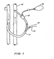
- the blood flow control system shown in Fig. 1 is, in essence a vascular tap which includes a primary fistula 11 that is connected between an artery 10 and a vein 12.
- a secondary fistula 14 leads to a venous sink 13 which may be any organ of the body such as the penis or the liver.
- a blood flow control means 15 is engaged with primary fistula 11 between the secondary fistula 14 and the vein 12. When the control device 16 is actuated the blood flow control means 15 restricts the flow of blood through the upper portion of the primary fistula 11 to increase the flow of blood to the venous sink 13 through the secondary fistula 14.
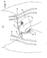
- Fig. 2 is an anterior view of the right groin showing a fistula 11 connected between the femoral artery 10 and the femoral vein 12. Normally, blood flows down the femoral artery 10 through the primary fistula 11 and returns to the heart through the femoral vein 12. A secondary fistula 14 connected to the primary fistula 11 directs blood flow to the penis 13.
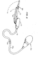
- the blood flow control device shown in the Fig. 2 includes an inflatable pressure means or balloon 20 which is made from any convenient implantable material and a manually compressible balloon 21 implated within the scrotum 15.
- the balloon 21 is connected to the balloon 20 through a tube 22 and has a two-way valve 23 at its mouth 24.
- the balloon 20 is held in position against the primary fistula 11 by a gortex tube 25.
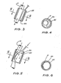
- the balloon 20 is deflated (as shown in Fig. 3)
- blood flow through the primary fistula ll is not impeded.
- the ballcon 20 is inflated by compressing the balloon 21, it presses against the primary fistula 11 to close or substantially close the fistula 11 so that blood flow from the femoral artery 10 is diverted through the secondary fistular to the penis 13.
- the blood flow control device of the invention creates an artificial system which allows normal blood flow through the primary fistula 11.
- the device is used for only short periods of time - say 20 minutes - to avoid thrombosis. As the entire device is implanted, it must be made from implantable materials.
- the valve 23 in the scrotum 17 is two-way to permit inflation and deflation of the balloon 20.
- F ig. 7 shows an alternative arrangement for the blood control system of the invention utilizing a cross-over fistula 11 which is connected between the artery 10 in the left leg and the vein 12 in the right leg. Otherwise the arrangement is the same as that shown in Fig. 2.
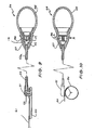
- the blood flow control device shown in Figs. 8 and 9 includes an inflatable pressure means or balloon 50 mounted on a balloon connector 51 having a passage-way 52 in communication with the interior of the balloon 50 and a connecting tube 53.
- a coupling 60 connects connecting tube 53 to connecting tube 53a.
- the other end of the connecting tube 53a is connected to a pump assembly 54 which includes a compressible balloon 55, a valve 56 and a valve body 57.
- a strap 61 is connected to the balloon connector 51 above the balloon 50 and has an aperture 62 through which is fed the connecting tube 53 and the connector 51 to be locked in the position shown in Fig. 10.
- FIG. 9 An alternative pump assembly is shown in Fig. 9 which also shows the balloon assembly inflated and the strap locked in position.
- the same numerals are used in respect of similar components and further description will be given in relation to Fig. 13.
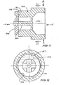
- valve 56 of Fig. 9 is shown in greater detail in Figs. 10 a 11 and has a body of silicone or other implantable flexible material which defines a valve chamber 57 as indicated in Fig. 9.
- An inlet 115 is connected to the reservoir 55 of an implantable blood flow control device.
- Outlet 116 is formed as a conical chamber 117 which has a peripheral flange 118 by means of which it is secured to valve 56 (see Fig. 9).
- the outlet 116 is connected to the balloon 50 of the above described blood flow control device.
- valve seat member 120 Within the valve chamber is a valve seat member 120 which has an annular body portion 121 that is held captive by the valve body. The rear wall and adjacent portions of the valve body are initially distorted so that the valve seat member 120 may be positioned within the chamber.
- the bore 122 of the valve seat member 120 is in communication with the inlet 115 and extends towards the outlet 116.
- annular valve seat 125 Within the bore 122 there is an annular valve seat 125 around the bore 122.
- a valve member or diaphragm 126 overlies and normally closes the valve seat 125.
- the diaphragm 126 is secured to and movable by the plunger 124. As can be seen in Fig. 12, the diaphragm 126 has a non-circular zone 127 by means of which it is secured to the valve seat 125 by a suitable adhesive.
- a hinge 128 is positioned adjacent to the zone of fixation 127.
- fluid from the reservoir can be forced into the inlet 115 and through the bore 122 where its pressure lifts the valve diaphragm 126 so that the fluid can pass through the outlet 116.
- the diaphragm 126 returns to its original position in which it seals against the valve seat 125.
- valve body When fluid is to be returned to the reservoir, the valve body is squeezed in the direction of arrows A whereupon the valve seat member 120 is distorted to move the plunger 124 towards the outlet 116 and in so doing lifts the valve diaphragm 126 from the valve seat 125.
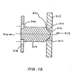
- the valve shown in Fig 13 has a body (not shown) of silicone or other implantable flexible material which defines 0 valve chamber.
- the body is of tubular form and has an inlet 213 and an outlet 214.
- valve seat member 215 which is disposed transversely of the valve chamber.
- the valve seat member 215 has a bore 216 in communication with the inlet 213 and a conical portion 217 which faces the inlet 213.
- a support member 218 having perforations 220 is transversely disposed in the valve cavity between the outlet 214 and the valve seat member 215.
- a valve plunger 219 extending from the support member 218 is adapted by means of conical face 221 to engage and close the bore 216 of the valve seat member 215.
- the inlet 213 is connected to the reservoir 55 of the implantable blood flow control device shown in Fig. 10 and the outlet 214 is connected to the balloon 50 of that device.
- fluid from the reservoir 55 is forced into the inlet 213 and through the bore 216 where its pressure lifts the plunger 219 so that fluid can pass through the perforations 220 of the support member 218 to the outlet 214.
- the plunger 219 will return to its original position in which it seals the bore 216. Pressure then present at the outlet 214 will retain the plunger 219 in its closed position.
- valve body 210 When fluid is to be returned to the reservoir 55, the valve body 210 is squeezed in the direction of the arrows A (see Fig. 10) whereupon the valve seat member 215 is distorted to move away from the plunger 219 towards the inlet 213 and in so doing placed the outlet 214 in communication with the inlet 213.
- valve shown in Fig. 14 is substantially similar to that shown in Fig. 13 and the same numerals are given to the equivalent components.
- the valve seat member 215 has a small perforation 226 for controlled flow of fluid back into the balloon 221.
- This arrangement has the advantaqe that by adjusting the diameter of the perforation 226 and the viscosity of the fluid, the valve will automatrcally return to its deflated position and thus control the duration that blood is diverted to the venous smk.
- Figs. 15 and 16 show an alternative flow control arrangement in which a magnet 300 is secured to the primary fistula 11 by means of a gortex cuff 301.
- the magnet 300 is located on the side of the fistula remote from the epidermis 302.
- An exterior magnet 303 when positioned on or near the epidermis 302, draws the magnet 300 towards it so as to partially restrict the internal lumin of the fistula 11.
- Other external actuators such as R.F. signals could be employed.
- the above described blood flow control systems may be used to control blood flow through an arterio-venous fistula so as to control or orgment the flow through extra corporeal circuits.
- the blood flow control system of the invention is employed as an arterio-venous fistula for haemodialysis patents, the device could be used for increased blood flow during dialysis and for decreased fistula flow during the off-dialysis period.
- the same concept could, in principle be used for any extra corporeal treatment procedure (for example plasmophoresis) as easily as it could be applied intra corporeally.
Landscapes
- Health & Medical Sciences (AREA)
- Life Sciences & Earth Sciences (AREA)
- Public Health (AREA)
- General Health & Medical Sciences (AREA)
- Surgery (AREA)
- Engineering & Computer Science (AREA)
- Biomedical Technology (AREA)
- Heart & Thoracic Surgery (AREA)
- Vascular Medicine (AREA)
- Veterinary Medicine (AREA)
- Animal Behavior & Ethology (AREA)
- Reproductive Health (AREA)
- Oral & Maxillofacial Surgery (AREA)
- Cardiology (AREA)
- Nuclear Medicine, Radiotherapy & Molecular Imaging (AREA)
- Transplantation (AREA)
- Medical Informatics (AREA)
- Molecular Biology (AREA)
- External Artificial Organs (AREA)
Applications Claiming Priority (4)
| Application Number | Priority Date | Filing Date | Title |
|---|---|---|---|
| AUPG951485 | 1985-02-28 | ||
| AUPG951385 | 1985-02-28 | ||
| AU9514/85 | 1985-02-28 | ||
| AU9513/85 | 1985-02-28 |
Publications (2)
| Publication Number | Publication Date |
|---|---|
| EP0200286A2 true EP0200286A2 (de) | 1986-11-05 |
| EP0200286A3 EP0200286A3 (de) | 1987-01-14 |
Family
ID=25642901
Family Applications (1)
| Application Number | Title | Priority Date | Filing Date |
|---|---|---|---|
| EP86300370A Withdrawn EP0200286A3 (de) | 1985-02-28 | 1986-01-20 | Regeleinrichtung für den Blutfluss |
Country Status (1)
| Country | Link |
|---|---|
| EP (1) | EP0200286A3 (de) |
Cited By (28)
| Publication number | Priority date | Publication date | Assignee | Title |
|---|---|---|---|---|
| EP0444063A4 (en) * | 1988-10-26 | 1991-09-25 | The Regents Of The University Of California | Penile erection system and method for use |
| WO2002091954A3 (en) * | 2001-05-15 | 2003-09-18 | American Med Syst | Implantable medical balloon and method of making |
| EP1563814A1 (de) * | 2000-02-10 | 2005-08-17 | Potencia Medical AG | Mechanische Vorrichtung zur Impotenzbehandlung |
| US7367938B2 (en) | 2000-02-10 | 2008-05-06 | Obtech Medical Ag | Mechanical impotence treatment apparatus |
| US7931582B2 (en) | 2000-02-11 | 2011-04-26 | Obtech Medical Ag | Controlled impotence treatment |
| US8096939B2 (en) | 2000-02-10 | 2012-01-17 | Obtech Medical Ag | Urinary incontinence treatment with wireless energy supply |
| US8096938B2 (en) | 1999-08-12 | 2012-01-17 | Obtech Medical Ag | Controlled anal incontinence disease treatment |
| US8126558B2 (en) | 2000-02-14 | 2012-02-28 | Obtech Medical Ag | Controlled penile prosthesis |
| US8290594B2 (en) | 2000-02-11 | 2012-10-16 | Obtech Medical Ag | Impotence treatment apparatus with energy transforming means |
| US8313423B2 (en) | 2000-02-14 | 2012-11-20 | Peter Forsell | Hydraulic anal incontinence treatment |
| US8509894B2 (en) | 2008-10-10 | 2013-08-13 | Milux Holding Sa | Heart help device, system, and method |
| US8545384B2 (en) | 1999-08-12 | 2013-10-01 | Obtech Medical Ag | Anal incontinence disease treatment with controlled wireless energy supply |
| US8556796B2 (en) | 2000-02-10 | 2013-10-15 | Obtech Medical Ag | Controlled urinary incontinence treatment |
| US8600510B2 (en) | 2008-10-10 | 2013-12-03 | Milux Holding Sa | Apparatus, system and operation method for the treatment of female sexual dysfunction |
| US8636809B2 (en) | 2008-01-29 | 2014-01-28 | Milux Holding Sa | Device for treating obesity |
| US8678997B2 (en) | 2000-02-14 | 2014-03-25 | Obtech Medical Ag | Male impotence prosthesis apparatus with wireless energy supply |
| US8696543B2 (en) | 2007-10-11 | 2014-04-15 | Kirk Promotion Ltd. | Method for controlling flow of intestinal contents in a patient's intestines |
| US8696745B2 (en) | 2008-10-10 | 2014-04-15 | Kirk Promotion Ltd. | Heart help device, system, and method |
| US8961448B2 (en) | 2008-01-28 | 2015-02-24 | Peter Forsell | Implantable drainage device |
| US8992409B2 (en) | 2007-10-11 | 2015-03-31 | Peter Forsell | Method for controlling flow in a bodily organ |
| US9278158B2 (en) | 2002-07-29 | 2016-03-08 | Peter Forsell | Multi-material incontinence treatment construction device |
| US9427301B2 (en) | 2002-07-29 | 2016-08-30 | Peter Forsell | Durable implant |
| US9662117B2 (en) | 2007-10-11 | 2017-05-30 | Peter Forsell | Apparatus for controlling flow in a bodily organ |
| US9949812B2 (en) | 2009-07-17 | 2018-04-24 | Peter Forsell | Vaginal operation method for the treatment of anal incontinence in women |
| US10219898B2 (en) | 2008-10-10 | 2019-03-05 | Peter Forsell | Artificial valve |
| FR3074416A1 (fr) * | 2017-12-04 | 2019-06-07 | Cousin Biotech | Dispositif implantable pour le traitement d'un dysfonctionnement sexuel masculin |
| US10952836B2 (en) | 2009-07-17 | 2021-03-23 | Peter Forsell | Vaginal operation method for the treatment of urinary incontinence in women |
| US11123171B2 (en) | 2008-10-10 | 2021-09-21 | Peter Forsell | Fastening means for implantable medical control assembly |
Families Citing this family (4)
| Publication number | Priority date | Publication date | Assignee | Title |
|---|---|---|---|---|
| US6464628B1 (en) | 1999-08-12 | 2002-10-15 | Obtech Medical Ag | Mechanical anal incontinence |
| EP1255513B1 (de) | 2000-02-14 | 2005-05-25 | Potencia Medical AG | Penisprothese |
| US8795153B2 (en) | 2007-10-11 | 2014-08-05 | Peter Forsell | Method for treating female sexual dysfunction |
| EP3120896A1 (de) | 2008-10-10 | 2017-01-25 | Kirk Promotion LTD. | System, vorrichtung und verfahren zur behandlung einer patientin mit sexueller dysfunktion |
Family Cites Families (9)
| Publication number | Priority date | Publication date | Assignee | Title |
|---|---|---|---|---|
| US3675656A (en) * | 1969-05-26 | 1972-07-11 | Salomon Hakim | Fluid operatable hemostat |
| US3699957A (en) * | 1970-10-01 | 1972-10-24 | Tecna Corp | Vas prosthesis for reversible sterilization |
| US3730186A (en) * | 1971-03-05 | 1973-05-01 | Univ California | Adjustable implantable artery-constricting device |
| US3758073A (en) * | 1971-10-26 | 1973-09-11 | R Schulte | Valve for physiological drainage actuable by lateral compression |
| US3939821A (en) * | 1973-11-14 | 1976-02-24 | Altair, Incorporated | Magnetically actuated tube compressing valve |
| FR2373272A1 (fr) * | 1976-12-07 | 1978-07-07 | Inst Nat Sante Rech Med | Dispositif de sphincter artificiel implantable |
| US4718410A (en) * | 1978-08-02 | 1988-01-12 | Hakky Said I | Surgical implants |
| US4475899A (en) * | 1982-09-03 | 1984-10-09 | Becton, Dickinson And Company | Shunt valve and method of use |
| US4546499A (en) * | 1982-12-13 | 1985-10-15 | Possis Medical, Inc. | Method of supplying blood to blood receiving vessels |
-
1986
- 1986-01-20 EP EP86300370A patent/EP0200286A3/de not_active Withdrawn
Cited By (36)
| Publication number | Priority date | Publication date | Assignee | Title |
|---|---|---|---|---|
| EP0444063A4 (en) * | 1988-10-26 | 1991-09-25 | The Regents Of The University Of California | Penile erection system and method for use |
| US8545384B2 (en) | 1999-08-12 | 2013-10-01 | Obtech Medical Ag | Anal incontinence disease treatment with controlled wireless energy supply |
| US8096938B2 (en) | 1999-08-12 | 2012-01-17 | Obtech Medical Ag | Controlled anal incontinence disease treatment |
| EP1563814A1 (de) * | 2000-02-10 | 2005-08-17 | Potencia Medical AG | Mechanische Vorrichtung zur Impotenzbehandlung |
| US7367938B2 (en) | 2000-02-10 | 2008-05-06 | Obtech Medical Ag | Mechanical impotence treatment apparatus |
| US8096939B2 (en) | 2000-02-10 | 2012-01-17 | Obtech Medical Ag | Urinary incontinence treatment with wireless energy supply |
| US8602966B2 (en) | 2000-02-10 | 2013-12-10 | Obtech Medical, AG | Mechanical impotence treatment apparatus |
| US8287444B2 (en) | 2000-02-10 | 2012-10-16 | Obtech Medical Ag | Mechanical impotence treatment apparatus |
| US8556796B2 (en) | 2000-02-10 | 2013-10-15 | Obtech Medical Ag | Controlled urinary incontinence treatment |
| US9655724B2 (en) | 2000-02-11 | 2017-05-23 | Peter Forsell | Controlled impotence treatment |
| US7931582B2 (en) | 2000-02-11 | 2011-04-26 | Obtech Medical Ag | Controlled impotence treatment |
| US8290594B2 (en) | 2000-02-11 | 2012-10-16 | Obtech Medical Ag | Impotence treatment apparatus with energy transforming means |
| US8678997B2 (en) | 2000-02-14 | 2014-03-25 | Obtech Medical Ag | Male impotence prosthesis apparatus with wireless energy supply |
| US8126558B2 (en) | 2000-02-14 | 2012-02-28 | Obtech Medical Ag | Controlled penile prosthesis |
| US8313423B2 (en) | 2000-02-14 | 2012-11-20 | Peter Forsell | Hydraulic anal incontinence treatment |
| WO2002091954A3 (en) * | 2001-05-15 | 2003-09-18 | American Med Syst | Implantable medical balloon and method of making |
| US7160325B2 (en) | 2001-05-15 | 2007-01-09 | Ams Research Corporation | Implantable medical balloon and valve |
| US9427301B2 (en) | 2002-07-29 | 2016-08-30 | Peter Forsell | Durable implant |
| US9278158B2 (en) | 2002-07-29 | 2016-03-08 | Peter Forsell | Multi-material incontinence treatment construction device |
| US8992409B2 (en) | 2007-10-11 | 2015-03-31 | Peter Forsell | Method for controlling flow in a bodily organ |
| US9662117B2 (en) | 2007-10-11 | 2017-05-30 | Peter Forsell | Apparatus for controlling flow in a bodily organ |
| US8696543B2 (en) | 2007-10-11 | 2014-04-15 | Kirk Promotion Ltd. | Method for controlling flow of intestinal contents in a patient's intestines |
| US8961448B2 (en) | 2008-01-28 | 2015-02-24 | Peter Forsell | Implantable drainage device |
| US9060771B2 (en) | 2008-01-29 | 2015-06-23 | Peter Forsell | Method and instrument for treating obesity |
| US8636809B2 (en) | 2008-01-29 | 2014-01-28 | Milux Holding Sa | Device for treating obesity |
| US8696745B2 (en) | 2008-10-10 | 2014-04-15 | Kirk Promotion Ltd. | Heart help device, system, and method |
| US8600510B2 (en) | 2008-10-10 | 2013-12-03 | Milux Holding Sa | Apparatus, system and operation method for the treatment of female sexual dysfunction |
| US9526649B2 (en) | 2008-10-10 | 2016-12-27 | Peter Forsell | Method and instrument for treating obesity |
| US8509894B2 (en) | 2008-10-10 | 2013-08-13 | Milux Holding Sa | Heart help device, system, and method |
| US9072907B2 (en) | 2008-10-10 | 2015-07-07 | Peter Forsell | Heart help device, system, and method |
| US10219898B2 (en) | 2008-10-10 | 2019-03-05 | Peter Forsell | Artificial valve |
| US10583234B2 (en) | 2008-10-10 | 2020-03-10 | Peter Forsell | Heart help device, system and method |
| US11123171B2 (en) | 2008-10-10 | 2021-09-21 | Peter Forsell | Fastening means for implantable medical control assembly |
| US9949812B2 (en) | 2009-07-17 | 2018-04-24 | Peter Forsell | Vaginal operation method for the treatment of anal incontinence in women |
| US10952836B2 (en) | 2009-07-17 | 2021-03-23 | Peter Forsell | Vaginal operation method for the treatment of urinary incontinence in women |
| FR3074416A1 (fr) * | 2017-12-04 | 2019-06-07 | Cousin Biotech | Dispositif implantable pour le traitement d'un dysfonctionnement sexuel masculin |
Also Published As
| Publication number | Publication date |
|---|---|
| EP0200286A3 (de) | 1987-01-14 |
Similar Documents
| Publication | Publication Date | Title |
|---|---|---|
| US4828544A (en) | Control of blood flow | |
| EP0200286A2 (de) | Regeleinrichtung für den Blutfluss | |
| US4958630A (en) | Method and apparatus for treating impotence | |
| US5048511A (en) | Method and apparatus for treating impotence | |
| US4634443A (en) | Single circuit elastofluidic sphincter | |
| US4417567A (en) | Artificial sphincter | |
| US4386601A (en) | Artificial sphincter | |
| US4574792A (en) | Penile erectile system | |
| US4419985A (en) | Apparatus for reversibly closing a body passage | |
| US4773403A (en) | Penile prosthesis | |
| EP0065853B1 (de) | Penisprothese mit Flüssigkeitssteuerung | |
| US4878889A (en) | Artificial sphincter device | |
| US4222377A (en) | Pressure regulated artificial sphincter systems | |
| US4383525A (en) | Implantable penile prosthetic cylinder with inclusive fluid reservoir | |
| US5807356A (en) | Catheter with valve | |
| US4369771A (en) | Penile erectile system | |
| US6491623B2 (en) | Device for preventing fecal incontinence | |
| US8348826B2 (en) | Surgical implant, in particular artificial sphincter with adjusted pressure | |
| US4587954A (en) | Elastomeric prosthetic sphincter | |
| JPH0357448A (ja) | 移植可能な括約筋装置 | |
| CA1318468C (en) | Inflatable penile prosthesis with bend release valve | |
| JPS6049508B2 (ja) | 人体の管状器官閉塞装置 | |
| US4549531A (en) | Artificial sphincter with inflatable cuff | |
| JPS61268247A (ja) | 補綴括約筋装置 | |
| CA1188053A (en) | Penile erectile system |
Legal Events
| Date | Code | Title | Description |
|---|---|---|---|
| PUAI | Public reference made under article 153(3) epc to a published international application that has entered the european phase |
Free format text: ORIGINAL CODE: 0009012 |
|
| AK | Designated contracting states |
Kind code of ref document: A2 Designated state(s): AT BE CH DE FR GB IT LI LU NL SE |
|
| PUAL | Search report despatched |
Free format text: ORIGINAL CODE: 0009013 |
|
| AK | Designated contracting states |
Kind code of ref document: A3 Designated state(s): AT BE CH DE FR GB IT LI LU NL SE |
|
| 17P | Request for examination filed |
Effective date: 19870305 |
|
| RAP1 | Party data changed (applicant data changed or rights of an application transferred) |
Owner name: QUOTIDIAN NO. 100 PTY. LIMITED |
|
| 17Q | First examination report despatched |
Effective date: 19890601 |
|
| STAA | Information on the status of an ep patent application or granted ep patent |
Free format text: STATUS: THE APPLICATION IS DEEMED TO BE WITHDRAWN |
|
| 18D | Application deemed to be withdrawn |
Effective date: 19901009 |
|
| RIN1 | Information on inventor provided before grant (corrected) |
Inventor name: PACE, GARY WILLIAM Inventor name: LANE, RODNEY JAMES Inventor name: TAYLOR, GEORGE RUSSELL |