EP0200233B1 - Brateinsatz für Grillvorrichtung - Google Patents
Brateinsatz für Grillvorrichtung Download PDFInfo
- Publication number
- EP0200233B1 EP0200233B1 EP86106065A EP86106065A EP0200233B1 EP 0200233 B1 EP0200233 B1 EP 0200233B1 EP 86106065 A EP86106065 A EP 86106065A EP 86106065 A EP86106065 A EP 86106065A EP 0200233 B1 EP0200233 B1 EP 0200233B1
- Authority
- EP
- European Patent Office
- Prior art keywords
- spit
- arm
- bowl
- roast
- axis
- Prior art date
- Legal status (The legal status is an assumption and is not a legal conclusion. Google has not performed a legal analysis and makes no representation as to the accuracy of the status listed.)
- Expired
Links
- 235000011389 fruit/vegetable juice Nutrition 0.000 claims abstract description 16
- 238000010411 cooking Methods 0.000 claims abstract description 8
- 238000010276 construction Methods 0.000 description 2
- 230000005484 gravity Effects 0.000 description 2
- 241000287828 Gallus gallus Species 0.000 description 1
- 238000004140 cleaning Methods 0.000 description 1
- 230000007423 decrease Effects 0.000 description 1
- 230000000694 effects Effects 0.000 description 1
- 238000010438 heat treatment Methods 0.000 description 1
- 239000002184 metal Substances 0.000 description 1
- 238000005070 sampling Methods 0.000 description 1
- 238000007790 scraping Methods 0.000 description 1
Images


Classifications
-
- A—HUMAN NECESSITIES
- A47—FURNITURE; DOMESTIC ARTICLES OR APPLIANCES; COFFEE MILLS; SPICE MILLS; SUCTION CLEANERS IN GENERAL
- A47J—KITCHEN EQUIPMENT; COFFEE MILLS; SPICE MILLS; APPARATUS FOR MAKING BEVERAGES
- A47J37/00—Baking; Roasting; Grilling; Frying
- A47J37/10—Frying pans, e.g. frying pans with integrated lids or basting devices
- A47J37/106—Integrated basting devices
-
- A—HUMAN NECESSITIES
- A47—FURNITURE; DOMESTIC ARTICLES OR APPLIANCES; COFFEE MILLS; SPICE MILLS; SUCTION CLEANERS IN GENERAL
- A47J—KITCHEN EQUIPMENT; COFFEE MILLS; SPICE MILLS; APPARATUS FOR MAKING BEVERAGES
- A47J37/00—Baking; Roasting; Grilling; Frying
- A47J37/04—Roasting apparatus with movably-mounted food supports or with movable heating implements; Spits
- A47J37/041—Roasting apparatus with movably-mounted food supports or with movable heating implements; Spits with food supports rotating about a horizontal axis
Definitions
- the invention relates to a roast rack adapted to equip a roasting pan and comprising a horizontal spit intended to be rotated about its axis and adapted to receive a part to be roasted, and a drip pan arranged under this spit to collect the cooking juices.
- the invention relates more specifically to a roast rack of this kind which further comprises an automatic sprinkler comprising at least one bucket carried by an arm driven in rotation by the spindle and extending away from this spit, this bucket being mounted so as to be able to pivot angularly limited about an axis parallel to the axis of rotation of the spit and distant from this axis of rotation, so as to take a certain amount of juice from the drip pan each time and pour this juice over the roasting pan.
- an automatic sprinkler comprising at least one bucket carried by an arm driven in rotation by the spindle and extending away from this spit, this bucket being mounted so as to be able to pivot angularly limited about an axis parallel to the axis of rotation of the spit and distant from this axis of rotation, so as to take a certain amount of juice from the drip pan each time and pour this juice over the roasting pan.
- the invention aims to allow a significantly simplified embodiment compared to that described in this patent and to bring in particular an improvement to the pivoting device of the bucket.
- one end of the bucket holder arm is rotatably mounted about a pivot axis in a bearing which extends parallel to the axis of rotation of the spit and which is carried by a flange integral in rotation with this pin, while the bucket is rigidly fixed on the other end of said arm, said rotary end of the arm carrying a finger extending between two spaced stops which are integral with the flange and with which this finger cooperates to limit pivoting.
- the use of the roast rack is made convenient and the operation of the sprinkler is always ensured since it requires no particular adjustment on the part of the user.
- the particular construction of the bucket holder arm and its arrangement with the stops ensure good stability of the bucket since said arm, from the start of its upward movement, comes, by gravity effect, to bear against the limiting stop of the back movement of the bucket, thus allowing this bucket to keep practically its full load up to the upper part of the part to be roasted.
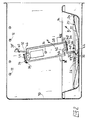
- Each bucket 30 is mounted so as to be able to perform a limited angular pivoting about an axis parallel to the axis of rotation of the spindle. 16 and distant from this axis of rotation.
- one of the ends 34 of the bucket support arm 32 is rotatably mounted around a pivot axis in a bearing 36 which extends parallel to the axis of rotation of the spindle 16 and which is carried by a flange 38 integral in rotation with this spindle, while the bucket 30 is rigidly fixed on the other end 40 of the arm 32, said rotary end 34 carrying a finger 42 oriented transversely to the pivot axis and extending between two spaced stops 44 and 46 which are integral with the flange 38 and with which the finger 42 cooperates to limit pivoting.
- the finger 42 for limiting the pivoting is simply constituted by a section of this arm itself, this section 42 being for this purpose adjacent to the rotary end 34 and forming with this end a bend 48.
- the flange 38 has a central passage with a square section which is threaded on the spindle 16, which ensures the rotational drive of this flange with the spindle.
- the axial immobilization of this flange on the spindle is ensured by tightening a butterfly screw 50 screwed into a lug of this flange and which is blocked on one of the lateral faces of the spindle.
- the stops 44 and 46 are constituted by spaced apart tabs integral with the flange 38 and oriented respectively in planes parallel to the axis of rotation of the spindle.
- the rotary end 34 of the arm 32 is trapped between the lug 44 and a counter plate 52 fixed to this lug and horse edge of said rotary end 34: the tab 44 and the counter plate 52 thus together constitute the pivot bearing 36.
- the counter plate 52 is formed by an elastic metal blade, one of which end 54, located on one side of the rotating part 34, is applied and fixed by rivets 56 to the tab 44, and the other end 58, located on the other side of the rotating part 34, is left free and has a raised edge 60 which can be grasped by hand to elastically separate this blade from the tab in order to extract the arm 32 from its bearing 36 by a lateral translational movement (arrow G in FIG. 3).
- the arms 32 are thus made removable from their support flange 38, this for cleaning or storage purposes for example.
- Each bucket 30 has an elongated shape in a direction parallel to the direction of the spindle 16.
- the bottom of this bucket has a series of transverse internal ribs 62 (fig. 4) suitable for providing in this bottom a series of compartments 64 of distribution cooking juices.
- this bucket first pivots slightly relative to the flange 38 (arrow H) in the opposite direction to the general rotational movement, so that the distance between the leading edge 66 and the axis of rotation of the spindle decreases enough to allow this bucket to continue its rotational movement around the axis of the spindle with scraping of the leading edge 66 over an area of the bottom of the broiler pan.
- the shaft 32 comes to bear against the stop 46 by gravity, this up to the high position of the bucket illustrated in 30 'in FIG. 2.
- the bucket retains practically its full load without spillage, thanks to the angular delay of this bucket relative to the general rotational movement.
- the spill occurs in the upper part of the ascent path, that is to say on the upper part of the roasting piece 18, and not on the side thereof. It is only after having largely exceeded the top of the course that the arm 32 swings abruptly relative to the flange 38 in the direction of rotation to come into abutment against the second stop 44, position for which the bucket is ready for a new removal. in the universal pan 20.
Landscapes
- Engineering & Computer Science (AREA)
- Food Science & Technology (AREA)
- Baking, Grill, Roasting (AREA)
- Massaging Devices (AREA)
- Packages (AREA)
- Table Devices Or Equipment (AREA)
- Pharmaceuticals Containing Other Organic And Inorganic Compounds (AREA)
- Food-Manufacturing Devices (AREA)
- Washing And Drying Of Tableware (AREA)
- Transition And Organic Metals Composition Catalysts For Addition Polymerization (AREA)
- Polyesters Or Polycarbonates (AREA)
- Liquid Crystal Substances (AREA)
Claims (7)
Priority Applications (1)
| Application Number | Priority Date | Filing Date | Title |
|---|---|---|---|
| AT86106065T ATE35893T1 (de) | 1985-05-03 | 1986-05-02 | Brateinsatz fuer grillvorrichtung. |
Applications Claiming Priority (2)
| Application Number | Priority Date | Filing Date | Title |
|---|---|---|---|
| FR8506764 | 1985-05-03 | ||
| FR8506764A FR2581305B1 (fr) | 1985-05-03 | 1985-05-03 | Porte-roti pour rotissoire |
Publications (2)
| Publication Number | Publication Date |
|---|---|
| EP0200233A1 EP0200233A1 (de) | 1986-11-05 |
| EP0200233B1 true EP0200233B1 (de) | 1988-07-27 |
Family
ID=9318937
Family Applications (1)
| Application Number | Title | Priority Date | Filing Date |
|---|---|---|---|
| EP86106065A Expired EP0200233B1 (de) | 1985-05-03 | 1986-05-02 | Brateinsatz für Grillvorrichtung |
Country Status (6)
| Country | Link |
|---|---|
| EP (1) | EP0200233B1 (de) |
| AT (1) | ATE35893T1 (de) |
| DE (1) | DE3660410D1 (de) |
| ES (1) | ES293919Y (de) |
| FR (1) | FR2581305B1 (de) |
| PT (1) | PT82497B (de) |
Families Citing this family (3)
| Publication number | Priority date | Publication date | Assignee | Title |
|---|---|---|---|---|
| DE102006001296A1 (de) * | 2006-01-10 | 2007-10-25 | BSH Bosch und Siemens Hausgeräte GmbH | Gargerät und Verfahren zum Begießen eines Garguts |
| EP2147601A1 (de) * | 2008-07-24 | 2010-01-27 | Fagor, S. Coop. | Werkzeug zum Bereiten von Brot für einen Haushaltsofen |
| KR101577496B1 (ko) * | 2013-04-30 | 2015-12-14 | 동부대우전자 주식회사 | 조리장치 |
Family Cites Families (7)
| Publication number | Priority date | Publication date | Assignee | Title |
|---|---|---|---|---|
| US2182225A (en) * | 1938-06-27 | 1939-12-05 | Gus G Garvis | Barbecue machine |
| FR1099625A (fr) * | 1954-02-18 | 1955-09-07 | Diffusion De Materiel Electr S | Dispositif destiné à arroser un rôti au cours de sa cuisson dans une rôtissoire électrique |
| FR68137E (fr) * | 1955-07-06 | 1958-04-08 | Alliages Legers De Paris Zeppe | Tournebroche |
| US2885951A (en) * | 1957-10-08 | 1959-05-12 | Whirlpool Co | Rotisserie with automatic basting mechanism |
| FR77639E (fr) * | 1960-04-30 | 1962-03-30 | Rôtissoire | |
| GB946355A (en) * | 1961-12-14 | 1964-01-08 | Parkinson Cowan Appliances Ltd | Improvements relating to spit roasters |
| FR1460331A (fr) * | 1965-12-17 | 1966-11-25 | Cadillac France | Perfectionnements aux dispositifs à brochettes pour rôtissoires et autres appareils de cuisson |
-
1985
- 1985-05-03 FR FR8506764A patent/FR2581305B1/fr not_active Expired - Fee Related
-
1986
- 1986-04-30 ES ES1986293919U patent/ES293919Y/es not_active Expired
- 1986-05-02 PT PT82497A patent/PT82497B/pt not_active IP Right Cessation
- 1986-05-02 AT AT86106065T patent/ATE35893T1/de not_active IP Right Cessation
- 1986-05-02 EP EP86106065A patent/EP0200233B1/de not_active Expired
- 1986-05-02 DE DE8686106065T patent/DE3660410D1/de not_active Expired
Also Published As
| Publication number | Publication date |
|---|---|
| FR2581305A1 (fr) | 1986-11-07 |
| ES293919U (es) | 1986-12-16 |
| DE3660410D1 (en) | 1988-09-01 |
| EP0200233A1 (de) | 1986-11-05 |
| ATE35893T1 (de) | 1988-08-15 |
| PT82497A (fr) | 1986-06-01 |
| FR2581305B1 (fr) | 1990-05-18 |
| PT82497B (pt) | 1992-07-31 |
| ES293919Y (es) | 1987-08-01 |
Similar Documents
| Publication | Publication Date | Title |
|---|---|---|
| EP2651271B1 (de) | Kochvorrichtung für nahrungsmittel mit einer rührklinge | |
| CA2162144C (fr) | Tourne-brochettes automatique | |
| CH669099A5 (fr) | Appareil pour cuire des deux cotes. | |
| EP0776624A1 (de) | Elektrischer Barbecue mit Bratvorrichtung | |
| EP1978855A1 (de) | Kochvorrichtung mit rührmittel und entsprechendes verfahren | |
| EP0737435A1 (de) | Küchengeschirr mit einem Deckel mit Ausgiessmöglichkeit | |
| FR2567711A1 (fr) | Tondeuse a gazon a moteur | |
| EP2522259A1 (de) | Vorrichtung zum Auspressen von Lebensmitteln, die mit einem Ausgießorgan mit regulierbarer Neigung ausgestattet ist | |
| EP0200233B1 (de) | Brateinsatz für Grillvorrichtung | |
| FR2726456A1 (fr) | Dispositif de blocage d'une cuve sur un support moteur pour appareil de preparation des aliments | |
| FR2892008A3 (fr) | Appareil a frire ou cuire inclinable | |
| CH635995A5 (fr) | Appareil a racler le fromage. | |
| FR2752374A1 (fr) | Dispositif releveur de produits, notamment de condiments, disposes dans un recipient | |
| EP1363524A2 (de) | Zuführeinheit für brotscheiben in einem toaster | |
| EP3685719B1 (de) | Elektrohaushaltsgerät zur essenszubereitung, das einen innenbehälter umfasst | |
| CH469475A (fr) | Rôtissoire | |
| EP1479330B1 (de) | Haushaltsgerät mit zwei mittels eines versetzten Gelenks angelenkten Kochplatten | |
| WO2015086965A1 (fr) | Appareil electromenager de preparation culinaire comportant un bras inferieur porte par un socle et un bras superieur relie au bras inferieur par un dispositif d'articulation | |
| FR2724305A1 (fr) | Dispositif de support de breche a viandes | |
| FR2610704A1 (fr) | Cuisiniere comportant notamment une plaque pivotante de protection | |
| FR2783148A1 (fr) | Dispositif pour permettre a une tres large gamme de batteurs electriques de battre de la pate contenue dans un recipient sans la presence permanente de leur utilisateur | |
| FR2722674A1 (fr) | Dispositif pour decoller des produits alimentaires tels que des crepes d'une plaque de cuisson | |
| FR2752373A1 (fr) | Dispositif releveur de produits, notamment de condiments, disposes dans un recipient | |
| FR2682583A1 (fr) | Tourne-brochettes automatique. | |
| EP1138236A2 (de) | Vorrichtung zum Schmelzen von Käsen |
Legal Events
| Date | Code | Title | Description |
|---|---|---|---|
| PUAI | Public reference made under article 153(3) epc to a published international application that has entered the european phase |
Free format text: ORIGINAL CODE: 0009012 |
|
| 17P | Request for examination filed |
Effective date: 19860929 |
|
| AK | Designated contracting states |
Kind code of ref document: A1 Designated state(s): AT BE CH DE GB IT LI NL SE |
|
| PUAB | Information related to the publication of an a document modified or deleted |
Free format text: ORIGINAL CODE: 0009199EPPU |
|
| PUAF | Information related to the publication of a search report (a3 document) modified or deleted |
Free format text: ORIGINAL CODE: 0009199SEPU |
|
| R17D | Deferred search report published (corrected) |
Effective date: 19861210 |
|
| RA1 | Application published (corrected) |
Date of ref document: 19861210 Kind code of ref document: A1 |
|
| 17Q | First examination report despatched |
Effective date: 19870421 |
|
| GRAA | (expected) grant |
Free format text: ORIGINAL CODE: 0009210 |
|
| AK | Designated contracting states |
Kind code of ref document: B1 Designated state(s): AT BE CH DE GB IT LI NL SE |
|
| REF | Corresponds to: |
Ref document number: 35893 Country of ref document: AT Date of ref document: 19880815 Kind code of ref document: T |
|
| GBT | Gb: translation of ep patent filed (gb section 77(6)(a)/1977) | ||
| REF | Corresponds to: |
Ref document number: 3660410 Country of ref document: DE Date of ref document: 19880901 |
|
| ITF | It: translation for a ep patent filed | ||
| PLBE | No opposition filed within time limit |
Free format text: ORIGINAL CODE: 0009261 |
|
| STAA | Information on the status of an ep patent application or granted ep patent |
Free format text: STATUS: NO OPPOSITION FILED WITHIN TIME LIMIT |
|
| 26N | No opposition filed | ||
| ITTA | It: last paid annual fee | ||
| PGFP | Annual fee paid to national office [announced via postgrant information from national office to epo] |
Ref country code: AT Payment date: 19930514 Year of fee payment: 8 |
|
| PGFP | Annual fee paid to national office [announced via postgrant information from national office to epo] |
Ref country code: CH Payment date: 19930518 Year of fee payment: 8 |
|
| PG25 | Lapsed in a contracting state [announced via postgrant information from national office to epo] |
Ref country code: AT Effective date: 19940502 |
|
| PG25 | Lapsed in a contracting state [announced via postgrant information from national office to epo] |
Ref country code: LI Effective date: 19940531 Ref country code: CH Effective date: 19940531 |
|
| EAL | Se: european patent in force in sweden |
Ref document number: 86106065.5 |
|
| REG | Reference to a national code |
Ref country code: CH Ref legal event code: PL |
|
| PGFP | Annual fee paid to national office [announced via postgrant information from national office to epo] |
Ref country code: DE Payment date: 19960503 Year of fee payment: 11 |
|
| PG25 | Lapsed in a contracting state [announced via postgrant information from national office to epo] |
Ref country code: DE Free format text: LAPSE BECAUSE OF NON-PAYMENT OF DUE FEES Effective date: 19980203 |
|
| PGFP | Annual fee paid to national office [announced via postgrant information from national office to epo] |
Ref country code: SE Payment date: 19980518 Year of fee payment: 13 |
|
| PGFP | Annual fee paid to national office [announced via postgrant information from national office to epo] |
Ref country code: BE Payment date: 19980709 Year of fee payment: 13 |
|
| PG25 | Lapsed in a contracting state [announced via postgrant information from national office to epo] |
Ref country code: SE Free format text: LAPSE BECAUSE OF NON-PAYMENT OF DUE FEES Effective date: 19990503 |
|
| PG25 | Lapsed in a contracting state [announced via postgrant information from national office to epo] |
Ref country code: BE Free format text: LAPSE BECAUSE OF NON-PAYMENT OF DUE FEES Effective date: 19990531 |
|
| BERE | Be: lapsed |
Owner name: MOULINEX Effective date: 19990531 |
|
| EUG | Se: european patent has lapsed |
Ref document number: 86106065.5 |
|
| PGFP | Annual fee paid to national office [announced via postgrant information from national office to epo] |
Ref country code: GB Payment date: 20010502 Year of fee payment: 16 |
|
| PGFP | Annual fee paid to national office [announced via postgrant information from national office to epo] |
Ref country code: NL Payment date: 20010531 Year of fee payment: 16 |
|
| REG | Reference to a national code |
Ref country code: GB Ref legal event code: IF02 |
|
| PG25 | Lapsed in a contracting state [announced via postgrant information from national office to epo] |
Ref country code: GB Free format text: LAPSE BECAUSE OF NON-PAYMENT OF DUE FEES Effective date: 20020502 |
|
| PG25 | Lapsed in a contracting state [announced via postgrant information from national office to epo] |
Ref country code: NL Free format text: LAPSE BECAUSE OF NON-PAYMENT OF DUE FEES Effective date: 20021201 |
|
| GBPC | Gb: european patent ceased through non-payment of renewal fee |
Effective date: 20020502 |
|
| NLV4 | Nl: lapsed or anulled due to non-payment of the annual fee |
Effective date: 20021201 |
|
| PG25 | Lapsed in a contracting state [announced via postgrant information from national office to epo] |
Ref country code: IT Free format text: LAPSE BECAUSE OF NON-PAYMENT OF DUE FEES;WARNING: LAPSES OF ITALIAN PATENTS WITH EFFECTIVE DATE BEFORE 2007 MAY HAVE OCCURRED AT ANY TIME BEFORE 2007. THE CORRECT EFFECTIVE DATE MAY BE DIFFERENT FROM THE ONE RECORDED. Effective date: 20050502 |