EP0200210B1 - Support de matrice pour moule à injection de matière plastique - Google Patents
Support de matrice pour moule à injection de matière plastique Download PDFInfo
- Publication number
- EP0200210B1 EP0200210B1 EP86105919A EP86105919A EP0200210B1 EP 0200210 B1 EP0200210 B1 EP 0200210B1 EP 86105919 A EP86105919 A EP 86105919A EP 86105919 A EP86105919 A EP 86105919A EP 0200210 B1 EP0200210 B1 EP 0200210B1
- Authority
- EP
- European Patent Office
- Prior art keywords
- groove
- moulding plate
- insert
- seating groove
- mold
- Prior art date
- Legal status (The legal status is an assumption and is not a legal conclusion. Google has not performed a legal analysis and makes no representation as to the accuracy of the status listed.)
- Expired - Lifetime
Links
- 238000000465 moulding Methods 0.000 title claims abstract description 25
- 229920003023 plastic Polymers 0.000 title claims abstract description 6
- 239000004033 plastic Substances 0.000 title claims abstract description 6
- 239000000463 material Substances 0.000 title claims abstract 3
- 238000002347 injection Methods 0.000 title description 2
- 239000007924 injection Substances 0.000 title description 2
- 238000001746 injection moulding Methods 0.000 claims abstract description 3
- 238000005192 partition Methods 0.000 claims abstract 2
- 230000004323 axial length Effects 0.000 description 6
- 238000007373 indentation Methods 0.000 description 3
- 238000003754 machining Methods 0.000 description 3
- 239000000956 alloy Substances 0.000 description 2
- 229910045601 alloy Inorganic materials 0.000 description 2
- 238000004519 manufacturing process Methods 0.000 description 2
- 238000003801 milling Methods 0.000 description 2
- 238000009417 prefabrication Methods 0.000 description 2
- 229910000831 Steel Inorganic materials 0.000 description 1
- 238000005520 cutting process Methods 0.000 description 1
- 238000005553 drilling Methods 0.000 description 1
- 238000000227 grinding Methods 0.000 description 1
- 238000000034 method Methods 0.000 description 1
- 230000000149 penetrating effect Effects 0.000 description 1
- 238000007493 shaping process Methods 0.000 description 1
- 239000010959 steel Substances 0.000 description 1
Images

Classifications
-
- B—PERFORMING OPERATIONS; TRANSPORTING
- B29—WORKING OF PLASTICS; WORKING OF SUBSTANCES IN A PLASTIC STATE IN GENERAL
- B29C—SHAPING OR JOINING OF PLASTICS; SHAPING OF MATERIAL IN A PLASTIC STATE, NOT OTHERWISE PROVIDED FOR; AFTER-TREATMENT OF THE SHAPED PRODUCTS, e.g. REPAIRING
- B29C45/00—Injection moulding, i.e. forcing the required volume of moulding material through a nozzle into a closed mould; Apparatus therefor
- B29C45/17—Component parts, details or accessories; Auxiliary operations
- B29C45/26—Moulds
- B29C45/2673—Moulds with exchangeable mould parts, e.g. cassette moulds
-
- B—PERFORMING OPERATIONS; TRANSPORTING
- B29—WORKING OF PLASTICS; WORKING OF SUBSTANCES IN A PLASTIC STATE IN GENERAL
- B29C—SHAPING OR JOINING OF PLASTICS; SHAPING OF MATERIAL IN A PLASTIC STATE, NOT OTHERWISE PROVIDED FOR; AFTER-TREATMENT OF THE SHAPED PRODUCTS, e.g. REPAIRING
- B29C45/00—Injection moulding, i.e. forcing the required volume of moulding material through a nozzle into a closed mould; Apparatus therefor
- B29C45/17—Component parts, details or accessories; Auxiliary operations
- B29C45/1742—Mounting of moulds; Mould supports
- B29C45/1744—Mould support platens
Definitions
- the invention relates to a molding plate according to the preamble of claim 1 (DE-A-3 021 827).
- Shaped elements into which item-forming engravings are incorporated must consist of a wide variety of higher-alloy steels, depending on the item. For this reason, as in the case of a molding plate which has become known through prior public use, the method has been adopted to restrict the molding elements provided with the engraving to inserts which frequently have a rectangular outer contour.
- the engraving-free mold plate which is also called the frame plate, can then consist of a standard alloy - except in exceptional cases - and only has a depression of a rectangular basic shape that corresponds to the outer shape of this mold insert and is open towards the mold parting plane to accommodate the mold insert carrying the engraving.
- the molding tool according to DE-A-3 021 827 mentioned at the beginning, from which the invention is based, has two engraving or molding inserts which are arranged interchangeably so that when a new molding is being sprayed, the entire molding tool does not have to be removed, but rather has to be removed predominant part can remain in the injection molding machine and only a part containing the mold inserts needs to be replaced.
- the mold inserts are attached to the respective mold plate with the help of laterally protruding clamping bars.
- Each mold insert is individually matched and adapted to the respective tool shape with regard to its outer dimensions; he completely fills the slot.
- JP-A-59-185 560 describes a plastic injection mold with a dovetail-shaped undercut receiving groove that runs over the entire axial length of a molding plate. An insert that completely and flush fills out is interchangeably held in the receiving groove.
- the object of the present invention is to further develop the known mold plate in such a way that it allows a very high degree of prefabrication, that is to say a standard, which requires little or no reworking from the mold maker .
- This object was achieved in accordance with the characterizing part of patent claim 1.
- This variability can consist in the fact that the standard parts manufacturer provides insert elements with defined different axial extensions or lengths, which the Mold maker taken into account when designing his mold insert.
- This has the advantage that the form-fit receptacles provided on the mold plate side, for example threaded holes for receiving the fastening screws and recesses for receiving projections of the insert elements, can already be completely prefabricated at the standard parts manufacturer. The mold maker only needs to insert the mold insert he has created into a standardized depression and fasten it there in the way he is used to.
- each insert element has an axial excess length, so that the mold maker adapts to the the individual axial length of his mold insert required by him only needs to shorten one insert element or both insert elements.
- the invention allows a receiving groove without form-fit receptacles, so that in certain applications it can be reserved for the mold maker to produce the form-fit receptacles on the mold plate side, which, because of their low machining volume, do not cause any harmful distortion stresses themselves.
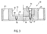
- the mold plate is generally designated by the reference number 10.
- the mold plate 10 has on its broad side facing a mold parting plane a straight receiving groove 11 which extends across the entire broad side, with two groove walls 12 and a groove bottom 13.
- the receiving groove 11 has a constant rectangular cross section over its entire axial groove length L N on.
- An insert element 14, which fills the groove cross section flush, is inserted into the receiving groove 11 on both end sides of the receiving groove 11.
- the axial length of each insert element 14 is designated L E
- the width of the axial insert element corresponds to the groove width B N.
- the distance between the straight, flat inner sides 15 of the insert elements 14, which extend perpendicular to the groove bottom 13, is denoted by L F.
- the distance L F essentially means the length of a not shown, the article or. shape-forming engraving containing insert.
- the freely visible groove walls 12, the freely visible groove bottom 13 and the inner side surfaces 15 of the insert elements 14 delimit a depression E, which serves for the form-fitting reception of the mold insert, not shown.
- insert elements 14 of different axial length L E can be provided, for example.
- L E the form-side arrangement of the form-fitting receptacles shown in the drawings at the two ends of the receiving groove 11.
- These form-plate-side form-fitting receptacles consist on the one hand of four threaded holes 16 provided in the groove bottom 13 for receiving the respective threaded part of fastening screws 17 passing through the insert elements are.
- a strip-shaped projection 19 provided on the lower surface of an insert element 14 engages in each of these channels 18. The strip-shaped projection 19 is penetrated at two points by through holes 20 for receiving the fastening screws 17.
- the insert elements 14 have an axial excess length L ü . This gives the mold maker the opportunity to shorten one insert element 14 or both insert elements 14 by the amount predetermined by the mold insert. In this embodiment, too, the position of the form-fit receptacles 16, 18 on the mold end side can be maintained.
- the mold plate normal 10 shown already has system bores, specifically bores 21 for receiving sliding bushes for guide columns, and open threaded blind holes 22 on the side facing away from the mold parting plane Inclusion of lag screws, not shown, which serve to brace a mold plate package consisting of several tool plates.
- the above-described receiving groove 11 can be used not only with rectangular shaped base plates but also with round shaped base plates.
- the insert elements 14 each have a part-circular contour on their outer edge region.
Landscapes
- Engineering & Computer Science (AREA)
- Manufacturing & Machinery (AREA)
- Mechanical Engineering (AREA)
- Moulds For Moulding Plastics Or The Like (AREA)
- Sealing Battery Cases Or Jackets (AREA)
- Insulating Bodies (AREA)
Claims (8)
Priority Applications (1)
| Application Number | Priority Date | Filing Date | Title |
|---|---|---|---|
| AT86105919T ATE54600T1 (de) | 1985-05-02 | 1986-04-29 | Formplatte fuer kunststoff-spritzgiesswerkzeuge. |
Applications Claiming Priority (2)
| Application Number | Priority Date | Filing Date | Title |
|---|---|---|---|
| DE3515790 | 1985-05-02 | ||
| DE3515790A DE3515790C1 (de) | 1985-05-02 | 1985-05-02 | Formplatte fuer Kunststoff-Spritzgiesswerkzeuge |
Publications (3)
| Publication Number | Publication Date |
|---|---|
| EP0200210A2 EP0200210A2 (fr) | 1986-11-05 |
| EP0200210A3 EP0200210A3 (en) | 1988-10-12 |
| EP0200210B1 true EP0200210B1 (fr) | 1990-07-18 |
Family
ID=6269656
Family Applications (1)
| Application Number | Title | Priority Date | Filing Date |
|---|---|---|---|
| EP86105919A Expired - Lifetime EP0200210B1 (fr) | 1985-05-02 | 1986-04-29 | Support de matrice pour moule à injection de matière plastique |
Country Status (3)
| Country | Link |
|---|---|
| EP (1) | EP0200210B1 (fr) |
| AT (1) | ATE54600T1 (fr) |
| DE (1) | DE3515790C1 (fr) |
Families Citing this family (2)
| Publication number | Priority date | Publication date | Assignee | Title |
|---|---|---|---|---|
| US5662946A (en) * | 1994-10-05 | 1997-09-02 | Motorola, Inc. | Adaptable mold base |
| DE10231551A1 (de) * | 2002-07-11 | 2004-01-22 | Balda Werkzeug- Und Vorrichtungsbau Gmbh | Formwerkzeug für Kunststoff-Gehäuseteile |
Family Cites Families (1)
| Publication number | Priority date | Publication date | Assignee | Title |
|---|---|---|---|---|
| DE3021827A1 (de) * | 1980-06-11 | 1981-12-17 | Plako Gmbh, Thermoplastik Und Formenbau, 5828 Ennepetal | Formwerkzeug fuer spritzgiessmaschinen |
-
1985
- 1985-05-02 DE DE3515790A patent/DE3515790C1/de not_active Expired
-
1986
- 1986-04-29 AT AT86105919T patent/ATE54600T1/de not_active IP Right Cessation
- 1986-04-29 EP EP86105919A patent/EP0200210B1/fr not_active Expired - Lifetime
Also Published As
| Publication number | Publication date |
|---|---|
| ATE54600T1 (de) | 1990-08-15 |
| EP0200210A2 (fr) | 1986-11-05 |
| DE3515790C1 (de) | 1986-09-25 |
| EP0200210A3 (en) | 1988-10-12 |
Similar Documents
| Publication | Publication Date | Title |
|---|---|---|
| DE2920931C2 (de) | Mit Stiftborsten versehender Borstenträger für eine Bürste, insbesondere Haarbürste, sowie Verfahren und Formwerkzeug zur Herstellung desselben | |
| DE3049282C2 (fr) | ||
| EP2803294B1 (fr) | Insert de moule pour un moule d'injection | |
| EP0730936A1 (fr) | Moule pour presse à vibrations | |
| WO2018069397A1 (fr) | Procédé et dispositif de fabrication d'un comprimé de métal dur et comprimé de métal dur | |
| EP0356600A1 (fr) | Procédé et machine pour fabriquer des fermetures à glissière | |
| EP0122566A2 (fr) | Dispositif pour la fabrication d'un outil abrasif | |
| DE3542840C2 (fr) | ||
| DE2140180A1 (de) | Vorrichtung mit fuehrungskanaelen fuer nadeln, stoesser, platinen oder andere maschinenteile betaetigende organe an textilmaschinen, insbesondere an rundstrick- und rundwirkmaschinen | |
| EP0200210B1 (fr) | Support de matrice pour moule à injection de matière plastique | |
| EP1004422A1 (fr) | Dispositif pour mouler par injection des articles en matière plastique et procédé pour fabriquer un tel dispositif | |
| DE3319463C2 (de) | Auskleidungsplatte für den Formraum an Formmaschinen | |
| EP1756930A1 (fr) | Procede pour fabriquer des paquets de toles de stator pour des moteurs lineaires a stator long sur des vehicules a sustentation magnetique | |
| EP0240753A2 (fr) | Procédé et appareil de fabrication d'objets moulés en matière plastique | |
| EP1336468B1 (fr) | Courroie crantée en plastique et méthode et appareil pour la fabrication de courroies crantées | |
| DE19627176C2 (de) | Vorrichtung zum Spritzgießen mit auswechselbaren Formleisten | |
| DE4439431A1 (de) | Verfahren und Vorrichtung zur Herstellung von Bürstenkörpern aus mindestens zwei Kunststoffkomponenten | |
| DE3621422C2 (fr) | ||
| CH621513A5 (fr) | ||
| DE19842092C2 (de) | Vorrichtung zur Herstellung von Spritz- oder Pressteilen | |
| DE2553059C3 (de) | Verfahren und Vorrichtung zum Schleifen von Schalenkernhälften aus Ferrit | |
| DE4103690C2 (de) | Spritzgießform für Spritzteile aus Kunststoff mit aneinandergereihten Abstufungen | |
| DE4233894C2 (de) | Spritzgieß- oder Preßwerkzeug zur Verarbeitung von Kunststoffmassen | |
| DE4320524C2 (de) | Spritzgießmaschine | |
| DE19543360C2 (de) | Streifenstanz-Schneidvorrichtung |
Legal Events
| Date | Code | Title | Description |
|---|---|---|---|
| PUAI | Public reference made under article 153(3) epc to a published international application that has entered the european phase |
Free format text: ORIGINAL CODE: 0009012 |
|
| AK | Designated contracting states |
Kind code of ref document: A2 Designated state(s): AT BE CH DE FR GB IT LI LU NL SE |
|
| 17P | Request for examination filed |
Effective date: 19861111 |
|
| PUAL | Search report despatched |
Free format text: ORIGINAL CODE: 0009013 |
|
| AK | Designated contracting states |
Kind code of ref document: A3 Designated state(s): AT BE CH DE FR GB IT LI LU NL SE |
|
| 17Q | First examination report despatched |
Effective date: 19890125 |
|
| ITF | It: translation for a ep patent filed | ||
| GRAA | (expected) grant |
Free format text: ORIGINAL CODE: 0009210 |
|
| AK | Designated contracting states |
Kind code of ref document: B1 Designated state(s): AT BE CH FR GB IT LI LU NL SE |
|
| REF | Corresponds to: |
Ref document number: 54600 Country of ref document: AT Date of ref document: 19900815 Kind code of ref document: T |
|
| ET | Fr: translation filed | ||
| GBT | Gb: translation of ep patent filed (gb section 77(6)(a)/1977) | ||
| ITTA | It: last paid annual fee | ||
| PLBE | No opposition filed within time limit |
Free format text: ORIGINAL CODE: 0009261 |
|
| STAA | Information on the status of an ep patent application or granted ep patent |
Free format text: STATUS: NO OPPOSITION FILED WITHIN TIME LIMIT |
|
| 26N | No opposition filed | ||
| PGFP | Annual fee paid to national office [announced via postgrant information from national office to epo] |
Ref country code: LU Payment date: 19940331 Year of fee payment: 9 |
|
| EPTA | Lu: last paid annual fee | ||
| EAL | Se: european patent in force in sweden |
Ref document number: 86105919.4 |
|
| PG25 | Lapsed in a contracting state [announced via postgrant information from national office to epo] |
Ref country code: LU Free format text: LAPSE BECAUSE OF NON-PAYMENT OF DUE FEES Effective date: 19950429 |
|
| PGFP | Annual fee paid to national office [announced via postgrant information from national office to epo] |
Ref country code: GB Payment date: 19960418 Year of fee payment: 11 |
|
| PGFP | Annual fee paid to national office [announced via postgrant information from national office to epo] |
Ref country code: FR Payment date: 19960419 Year of fee payment: 11 |
|
| PGFP | Annual fee paid to national office [announced via postgrant information from national office to epo] |
Ref country code: BE Payment date: 19960424 Year of fee payment: 11 |
|
| PGFP | Annual fee paid to national office [announced via postgrant information from national office to epo] |
Ref country code: AT Payment date: 19960426 Year of fee payment: 11 |
|
| PGFP | Annual fee paid to national office [announced via postgrant information from national office to epo] |
Ref country code: SE Payment date: 19960430 Year of fee payment: 11 Ref country code: NL Payment date: 19960430 Year of fee payment: 11 Ref country code: CH Payment date: 19960430 Year of fee payment: 11 |
|
| PG25 | Lapsed in a contracting state [announced via postgrant information from national office to epo] |
Ref country code: GB Effective date: 19970429 Ref country code: AT Effective date: 19970429 |
|
| PG25 | Lapsed in a contracting state [announced via postgrant information from national office to epo] |
Ref country code: SE Effective date: 19970430 Ref country code: LI Free format text: LAPSE BECAUSE OF NON-PAYMENT OF DUE FEES Effective date: 19970430 Ref country code: CH Free format text: LAPSE BECAUSE OF NON-PAYMENT OF DUE FEES Effective date: 19970430 Ref country code: BE Effective date: 19970430 |
|
| BERE | Be: lapsed |
Owner name: HASCO-NORMALIEN HASENCLEVER + CO. Effective date: 19970430 |
|
| PG25 | Lapsed in a contracting state [announced via postgrant information from national office to epo] |
Ref country code: NL Effective date: 19971101 |
|
| REG | Reference to a national code |
Ref country code: CH Ref legal event code: PL |
|
| GBPC | Gb: european patent ceased through non-payment of renewal fee |
Effective date: 19970429 |
|
| PG25 | Lapsed in a contracting state [announced via postgrant information from national office to epo] |
Ref country code: FR Free format text: LAPSE BECAUSE OF NON-PAYMENT OF DUE FEES Effective date: 19971231 |
|
| NLV4 | Nl: lapsed or anulled due to non-payment of the annual fee |
Effective date: 19971101 |
|
| EUG | Se: european patent has lapsed |
Ref document number: 86105919.4 |
|
| REG | Reference to a national code |
Ref country code: FR Ref legal event code: ST |
|
| PG25 | Lapsed in a contracting state [announced via postgrant information from national office to epo] |
Ref country code: IT Free format text: LAPSE BECAUSE OF NON-PAYMENT OF DUE FEES;WARNING: LAPSES OF ITALIAN PATENTS WITH EFFECTIVE DATE BEFORE 2007 MAY HAVE OCCURRED AT ANY TIME BEFORE 2007. THE CORRECT EFFECTIVE DATE MAY BE DIFFERENT FROM THE ONE RECORDED. Effective date: 20050429 |