EP0200210B1 - Moulding plate for a plastic material injection mould - Google Patents
Moulding plate for a plastic material injection mould Download PDFInfo
- Publication number
- EP0200210B1 EP0200210B1 EP86105919A EP86105919A EP0200210B1 EP 0200210 B1 EP0200210 B1 EP 0200210B1 EP 86105919 A EP86105919 A EP 86105919A EP 86105919 A EP86105919 A EP 86105919A EP 0200210 B1 EP0200210 B1 EP 0200210B1
- Authority
- EP
- European Patent Office
- Prior art keywords
- groove
- moulding plate
- insert
- seating groove
- mold
- Prior art date
- Legal status (The legal status is an assumption and is not a legal conclusion. Google has not performed a legal analysis and makes no representation as to the accuracy of the status listed.)
- Expired - Lifetime
Links
Images

Classifications
-
- B—PERFORMING OPERATIONS; TRANSPORTING
- B29—WORKING OF PLASTICS; WORKING OF SUBSTANCES IN A PLASTIC STATE IN GENERAL
- B29C—SHAPING OR JOINING OF PLASTICS; SHAPING OF MATERIAL IN A PLASTIC STATE, NOT OTHERWISE PROVIDED FOR; AFTER-TREATMENT OF THE SHAPED PRODUCTS, e.g. REPAIRING
- B29C45/00—Injection moulding, i.e. forcing the required volume of moulding material through a nozzle into a closed mould; Apparatus therefor
- B29C45/17—Component parts, details or accessories; Auxiliary operations
- B29C45/26—Moulds
- B29C45/2673—Moulds with exchangeable mould parts, e.g. cassette moulds
-
- B—PERFORMING OPERATIONS; TRANSPORTING
- B29—WORKING OF PLASTICS; WORKING OF SUBSTANCES IN A PLASTIC STATE IN GENERAL
- B29C—SHAPING OR JOINING OF PLASTICS; SHAPING OF MATERIAL IN A PLASTIC STATE, NOT OTHERWISE PROVIDED FOR; AFTER-TREATMENT OF THE SHAPED PRODUCTS, e.g. REPAIRING
- B29C45/00—Injection moulding, i.e. forcing the required volume of moulding material through a nozzle into a closed mould; Apparatus therefor
- B29C45/17—Component parts, details or accessories; Auxiliary operations
- B29C45/1742—Mounting of moulds; Mould supports
- B29C45/1744—Mould support platens
Definitions
- the invention relates to a molding plate according to the preamble of claim 1 (DE-A-3 021 827).
- Shaped elements into which item-forming engravings are incorporated must consist of a wide variety of higher-alloy steels, depending on the item. For this reason, as in the case of a molding plate which has become known through prior public use, the method has been adopted to restrict the molding elements provided with the engraving to inserts which frequently have a rectangular outer contour.
- the engraving-free mold plate which is also called the frame plate, can then consist of a standard alloy - except in exceptional cases - and only has a depression of a rectangular basic shape that corresponds to the outer shape of this mold insert and is open towards the mold parting plane to accommodate the mold insert carrying the engraving.
- the molding tool according to DE-A-3 021 827 mentioned at the beginning, from which the invention is based, has two engraving or molding inserts which are arranged interchangeably so that when a new molding is being sprayed, the entire molding tool does not have to be removed, but rather has to be removed predominant part can remain in the injection molding machine and only a part containing the mold inserts needs to be replaced.
- the mold inserts are attached to the respective mold plate with the help of laterally protruding clamping bars.
- Each mold insert is individually matched and adapted to the respective tool shape with regard to its outer dimensions; he completely fills the slot.
- JP-A-59-185 560 describes a plastic injection mold with a dovetail-shaped undercut receiving groove that runs over the entire axial length of a molding plate. An insert that completely and flush fills out is interchangeably held in the receiving groove.
- the object of the present invention is to further develop the known mold plate in such a way that it allows a very high degree of prefabrication, that is to say a standard, which requires little or no reworking from the mold maker .
- This object was achieved in accordance with the characterizing part of patent claim 1.
- This variability can consist in the fact that the standard parts manufacturer provides insert elements with defined different axial extensions or lengths, which the Mold maker taken into account when designing his mold insert.
- This has the advantage that the form-fit receptacles provided on the mold plate side, for example threaded holes for receiving the fastening screws and recesses for receiving projections of the insert elements, can already be completely prefabricated at the standard parts manufacturer. The mold maker only needs to insert the mold insert he has created into a standardized depression and fasten it there in the way he is used to.
- each insert element has an axial excess length, so that the mold maker adapts to the the individual axial length of his mold insert required by him only needs to shorten one insert element or both insert elements.
- the invention allows a receiving groove without form-fit receptacles, so that in certain applications it can be reserved for the mold maker to produce the form-fit receptacles on the mold plate side, which, because of their low machining volume, do not cause any harmful distortion stresses themselves.
- the mold plate is generally designated by the reference number 10.
- the mold plate 10 has on its broad side facing a mold parting plane a straight receiving groove 11 which extends across the entire broad side, with two groove walls 12 and a groove bottom 13.
- the receiving groove 11 has a constant rectangular cross section over its entire axial groove length L N on.
- An insert element 14, which fills the groove cross section flush, is inserted into the receiving groove 11 on both end sides of the receiving groove 11.
- the axial length of each insert element 14 is designated L E
- the width of the axial insert element corresponds to the groove width B N.
- the distance between the straight, flat inner sides 15 of the insert elements 14, which extend perpendicular to the groove bottom 13, is denoted by L F.
- the distance L F essentially means the length of a not shown, the article or. shape-forming engraving containing insert.
- the freely visible groove walls 12, the freely visible groove bottom 13 and the inner side surfaces 15 of the insert elements 14 delimit a depression E, which serves for the form-fitting reception of the mold insert, not shown.
- insert elements 14 of different axial length L E can be provided, for example.
- L E the form-side arrangement of the form-fitting receptacles shown in the drawings at the two ends of the receiving groove 11.
- These form-plate-side form-fitting receptacles consist on the one hand of four threaded holes 16 provided in the groove bottom 13 for receiving the respective threaded part of fastening screws 17 passing through the insert elements are.
- a strip-shaped projection 19 provided on the lower surface of an insert element 14 engages in each of these channels 18. The strip-shaped projection 19 is penetrated at two points by through holes 20 for receiving the fastening screws 17.
- the insert elements 14 have an axial excess length L ü . This gives the mold maker the opportunity to shorten one insert element 14 or both insert elements 14 by the amount predetermined by the mold insert. In this embodiment, too, the position of the form-fit receptacles 16, 18 on the mold end side can be maintained.
- the mold plate normal 10 shown already has system bores, specifically bores 21 for receiving sliding bushes for guide columns, and open threaded blind holes 22 on the side facing away from the mold parting plane Inclusion of lag screws, not shown, which serve to brace a mold plate package consisting of several tool plates.
- the above-described receiving groove 11 can be used not only with rectangular shaped base plates but also with round shaped base plates.
- the insert elements 14 each have a part-circular contour on their outer edge region.
Abstract
Description
Die Erfindung betrifft eine Formplatte entsprechend dem Oberbegriff des Patentanspruchs 1 (DE-A-3 021 827).The invention relates to a molding plate according to the preamble of claim 1 (DE-A-3 021 827).
Formelemente, in die artikelbildende Gravuren eingearbeitet werden, müssen aus - artikelbedingt - unterschiedlichsten höherlegierten Stählen bestehen. Deshalb ist man - wie bei einer durch offenkundige Vorbenutzung bekanntgewordenen Formplatte - dazu übergegangen, die mit der Gravur versehenen Formelemente auf Einsätze zu beschränken, die häufig eine rechteckige Außenkontur aufweisen. Die gravurlose Formplatte, die auch Rahmenplatte genannt wird, kann sodann - bis auf Ausnahmefälle - aus einer Standardlegierung bestehen und weist zur Aufnahme des die Gravur tragenden Formeinsatzes lediglich eine der Außenform dieses Formeinsatzes entsprechende, zur Formtrennebene hin offene Einsenkung rechteckiger Grundform auf. Je nach Artikel- oder Werkzeuggestaltung ist es auch möglich, innerhalb einer Formplatte mehrere Einsenkungen zur Aufnahme je eines Formeinsatzes vorzusehen.Shaped elements into which item-forming engravings are incorporated must consist of a wide variety of higher-alloy steels, depending on the item. For this reason, as in the case of a molding plate which has become known through prior public use, the method has been adopted to restrict the molding elements provided with the engraving to inserts which frequently have a rectangular outer contour. The engraving-free mold plate, which is also called the frame plate, can then consist of a standard alloy - except in exceptional cases - and only has a depression of a rectangular basic shape that corresponds to the outer shape of this mold insert and is open towards the mold parting plane to accommodate the mold insert carrying the engraving. Depending on the design of the article or tool, it is also possible to provide several indentations within one mold plate for receiving one mold insert each.
Die Herstellung derartiger Form- bzw. Rahmenplatten ist sowohl aus der Sicht des Formenbauers als auch aus der Sicht des Normalienherstellers bislang recht unbefriedigend. Hierzu muß zunächst vorausgesetzt werden, daß jeder Formeinsatz - bedingt durch die Größe des Artikels - unterschiedliche Abmessungen hat. In jedem Fall ist es aber so, daß die Einsenkung zur Aufnahme des Formeinsatzes spangebende Verformungsarbeiten (Bohren und Fräsen) mit einem solchen Zerspanungsvolumen erfordert, daß ein Spannungsverzug regelmäßig unvermeidlich ist. Aus diesem Grunde verläuft die Herstellung einer Formplatte derart, daß in die bereits plangeschliffene Ausgangsplatte zunächst die Einsenkung bzw. die Einsenkungen eingearbeitet werden, wonach - nach erneutem Planschleifen - die Systembohrungen, also insbesondere die hochgenauen Führungsbohrungen zur Aufnahme der Führungssäulen, hergestellt werden. Dies bedeutet, daß der Vorfertigungsgrad für eine Formplattennormalie, die bislang lediglich eine plangeschliffene und ansonsten nicht bearbeitete Platte von zumeist rechteckiger oder auch runder Grundform darstellt, sehr gering ist.The production of such shaped or frame plates has been quite unsatisfactory from the point of view of the mold maker as well as from the point of view of the standard parts manufacturer. For this it must first be assumed that each mold insert has different dimensions due to the size of the article. In any case, it is the case that the depression for receiving the mold insert requires shaping work (drilling and milling) with such a machining volume that a delay in tension is regularly unavoidable. For this reason, the production of a shaped plate proceeds in such a way that the indentation or indentations are first worked into the face plate that has already been ground, after which - after surface grinding again - the system bores, in particular the high-precision guide bores for receiving the guide columns, are made. This means that the degree of prefabrication for a mold plate standard, which so far has only been a flat-ground and otherwise not machined plate of mostly rectangular or round basic shape, is very low.
Das Formwerkzeug nach der eingangs erwähnten DE-A-3 021 827, von der die Erfindung ausgeht, weist zwei Gravur- bzw. Formeinsätze auf, die auswechselbar angeordnet sind, damit beim Spritzen eines neuen Formlings nicht das gesamte Formwerkzeug ausgebaut werden muß, sondern sein überwiegender Teil in der Spritzgießmaschine verbleiben kann und nur ein die Formeinsätze enthaltender Teil ausgewechselt zu werden braucht. Die Formeinsätze sind mit Hilfe von seitlich vorstehenden Spannleisten an der jeweiligen Formplatte befestigt. Jeder Formeinsatz ist individuell hinsichtlich seiner Außenabmessungen auf die jeweilige Werkzeugform abgestimmt und daran angepaßt; dabei füllt er die Aufnahme-Nut vollständig aus.The molding tool according to DE-A-3 021 827 mentioned at the beginning, from which the invention is based, has two engraving or molding inserts which are arranged interchangeably so that when a new molding is being sprayed, the entire molding tool does not have to be removed, but rather has to be removed predominant part can remain in the injection molding machine and only a part containing the mold inserts needs to be replaced. The mold inserts are attached to the respective mold plate with the help of laterally protruding clamping bars. Each mold insert is individually matched and adapted to the respective tool shape with regard to its outer dimensions; he completely fills the slot.
In der JP-A-59-185 560 ist eine Kunststoff-Spritzgießform mit einer über die gesamte Axiallänge einer Formplatte geführten schwalbenschwanzförmig hinterschnittenen Aufnahme-Nut beschrieben. In der Aufnahme-Nut ist ein diese gänzlich und bündig ausfüllender Einsatz auswechselbar rastgehaltert.JP-A-59-185 560 describes a plastic injection mold with a dovetail-shaped undercut receiving groove that runs over the entire axial length of a molding plate. An insert that completely and flush fills out is interchangeably held in the receiving groove.
Ausgehend von der durch die DE-A-3 021 827 bekanntgewordenen Formplatte, liegt dieser Erfindung die Aufgabe zugrunde, die bekannte Formplatte so weiterzuentwickeln, daß sie einen sehr weitgehenden Vorfertigungsgrad, also eine Normalie gestattet, die beim Formenbauer keine oder nur noch geringe Nacharbeiten erfordert. Diese Aufgabe wurde entsprechend dem Kennzeichenteil des Patentanspruchs 1 gelöst.Starting from the mold plate which became known from DE-A-3 021 827, the object of the present invention is to further develop the known mold plate in such a way that it allows a very high degree of prefabrication, that is to say a standard, which requires little or no reworking from the mold maker . This object was achieved in accordance with the characterizing part of patent claim 1.
Nach der Erfindung kommt es weniger auf die Verwendung auswechselbarer Formeinsätze zur Erleichterung von Auf- und Abspannarbeiten an als darauf, das formplattenseitige Einbaufeld derart geschickt für den Formenbauer vorzubereiten, daß seine Tätigkeit auf ein Minimum an Vorbereitungsarbeiten beschränkt bleibt. Entsprechend der Erfindung ist es jetzt bereits dem Normalienhersteller möglich, mehrere oder nur eine zur Formtrennebene hin offene gerade Aufnahme-Nut quer Über eine Breitseite einer Formplatte hinweg in die Oberfläche einzufräsen. Der Nutquerschnitt ist über die gesamte Nutlänge gleichbleibend. Zweckmäßig it der Nutquerschnitt rechteckig, so daß eine solche Aufnahme-Nut auf einfache Weise mit einem geraden Frässchnitt hergestellt werden kann. Nach Einbringen de Aufnahme-Nut kann der Normalienhersteller die Formplatte planschleifen und anschließend mit den Systembohrungen, insbesondere mit den hochgenauen Führungsbohrungen zur Aufnahme der Führungssäulen, versehen. Außerdem fertigt der Normalienhersteller Einsatz elemente, die den Nutquerschnitt bündig ausfüllen. Bei Ausbildung und Anwendung der Einsatzelemente bestehen unterschiedliche Möglichkeiten, von denen einige aufgezählt werden sollen:
- Hauptaufgabe zweier in der Aufnahme-Nut voneinander distanzierter Einsatzelemente ist es hierbei, zwischen ihren sich über die Nutbreite erstreckenden Querflächen sowie gemeinsam mit dem Nutboden und außerdem mit den zwischen den beiden Einsatzelementen befindlichen Nutwandungen die Einsenkung zur Aufnahme des Formeinsatzes zu definieren. Bei durch die jeweilige Nutbreite festgelegten Breiten des Einsatzes ist die axiale Länge der Einsenkung zur Aufnahme des Formeinsatzes variabel.
- The main task of two insert elements spaced apart from one another in the receiving groove is to define the depression for receiving the mold insert between their transverse surfaces extending over the groove width and together with the groove bottom and also with the groove walls between the two insert elements. With the width of the insert determined by the respective groove width, the axial length of the depression for receiving the mold insert is variable.
Diese Variabilität kann einmal darin bestehen, daß der Normalienhersteller Einsatzelemente mit festgelegten unterschiedlichen axialen Erstreckungen bzw. Längen bereitstellt, die der Formenbauer bei der Konzeption seines Formeinsatzes berücksichtigt. Hierbei ergibt sich der Vorteil, daß die formplattenseitig vorgesehenen Formschlußaufnahmen, also z.B. Gewindebohrungen zurAufnahme der Befestigungsschrauben und Aussparungen zur Aufnahme von Vorsprüngen der Einsatzelemente, bereits gänzlich beim Normalienhersteller vorgefertigt werden können. Der Formenbauer braucht also nur den von ihm erstellten Formeinsatz in eine standardisierte Einsenkung einzusetzen und dort auf die bisherige ihm geläufige Weise zu befestigen.This variability can consist in the fact that the standard parts manufacturer provides insert elements with defined different axial extensions or lengths, which the Mold maker taken into account when designing his mold insert. This has the advantage that the form-fit receptacles provided on the mold plate side, for example threaded holes for receiving the fastening screws and recesses for receiving projections of the insert elements, can already be completely prefabricated at the standard parts manufacturer. The mold maker only needs to insert the mold insert he has created into a standardized depression and fasten it there in the way he is used to.
Eine andere Variante, bei welcher ebenfalls die formplattenseitigen Formschlußaufnahmen in einer bestimmten Teilung, al beispielsweise jeweils an den beid Enden der Aufnahme-Nut, vorgesehen sein können, bestehten darin: Jedes Einsatzelement weist eine axiale Überlänge auf, so daß der Formenbauer in Anpassung an die von ihm geforderte individuelle axiale Länge seines Formeinsatzes lediglich ein Einsatzelement oder beide Einsatzelemente zu kürzen braucht.Another variant, in which the form-fitting receptacles on the mold plate side can also be provided in a certain division, for example at the two ends of the receiving groove, consisted of: Each insert element has an axial excess length, so that the mold maker adapts to the the individual axial length of his mold insert required by him only needs to shorten one insert element or both insert elements.
.Schließlich läßt die Erfindung eine Aufnahme-Nut ohne Formschlußaufnahmen zu, so daß es in bestimmten Anwendungsfällen dem Formenbauer vorbehalten sein kann, in Anpassung an seinen Formeinsatz die formplattenseitigen Formschlußaufnahmen, die aufgrund ihres geringen Zerspanungsvolumens keine schädlichen Verzugsspannungen hervorrufen, selbst herzustellen.Finally, the invention allows a receiving groove without form-fit receptacles, so that in certain applications it can be reserved for the mold maker to produce the form-fit receptacles on the mold plate side, which, because of their low machining volume, do not cause any harmful distortion stresses themselves.
In den Zeichnungen ist ein bevorzugtes Ausführungsbeispiel entsprechend der Erfindung näher dargestellt, es zeigen
- Fig. 1 eine Draufsicht auf eine Formplatte, von der Formtrennebene her gesehen,
- Fig. 2 einen axialen Längsschnitt entsprechend der in Fig. 1 eingetragenen und mit 11-11 bezeichneten abgeknickten Schnittlinie und
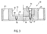
- Fig. 3 einen Querschnitt entsprechend der in Fig. 1 mit 111-111 bezeichneten Schnittlinie, wobei das dort gezeigte Einsatzelement nur zur Hälfte dargestellt ist.
- 1 is a plan view of a mold plate, seen from the mold parting plane,
- Fig. 2 is an axial longitudinal section corresponding to the kinked cutting line and entered in Fig. 1 and designated 11-11
- Fig. 3 shows a cross section corresponding to the section line labeled 111-111 in Fig. 1, wherein the insert element shown there is only half shown.
In den Zeichnungen ist die Formplatte insgesamt mit der Bezugsziffer 10 bezeichnet.In the drawings, the mold plate is generally designated by the
Die Formplatte 10 weist auf ihrer einer Formtrennebene zugewandten Breitseite eine sich über die gesamte Breitseite quer hinweg erstreckende geradeAufnahme-Nut 11 auf, mit zwei Nutwänden 12 und einem Nutboden 13. Die Aufnahme-Nut 11 weist auf ihrer gesamten axialen Nutlänge LN einen gleichbleibenden Rechteckquerschnitt auf. An beiden Endseiten der Aufnahme-Nut 11 ist jeweils ein Einsatzelement 14, der welches den Nutquerschnitt bündig ausfüllt, in Aufnahme-Nut 11 eingesetzt. Die axiale Länge jedes Einsatzelementes 14 ist mit LE bezeichnet, während die Breite des axialen Einsatzelementes der Nutbreite BN entspricht. Der Abstand zwischen den geraden, ebenen und sich zum Nutboden 13 senkrecht erstreckenden inneren Seitenflächen 15 der Einsatzelemente 14 ist mit LF bezeichnet. Der Abstand LF bedeutet zugleich im wesentlichen die Länge eines nicht dargestellten, die artikel-bzw. formbildende Gravur enthaltenden Formeinsatzes.The
Wie aus der Zusammenschau der Fig. 1 und 2 ohne weiteres zu ersehen, begrenzen die frei sichtbaren Nutwände 12, der frei sichtbare Nutboden 13 sowie die inneren Seitenflächen 15 der Einsatzelemente 14 eine Einsenkung E, die der satten formschlüssigen Aufnahme des nicht dargestellten Formeinsatzes dient.As can be seen from the synopsis of FIGS. 1 and 2 without further ado, the freely
Zur Normalisierung der in den Zeichnungen dargestellten Formplatte 10 ist es möglich, gängige Formplattengrößen mit Aufnahme-Nuten 11 weniger unterschiedlicher Breiten bereitzuhalten, auf die sich der Formenbauer einstellen kann. Die Variabilität hinsichtlich unterschiedlicher Abmessungen des Formeinsatzes ist grundsätzlich durch die jeweilige axiale Länge LE eines Einsatzelementes 14 bzw. durch dessen Befestigungsposition bezüglich der mit XN bezeichneten Nutlängsrichtung gegeben.In order to normalize the
Zur Erzielung dieser Variabilität können beispielsweise Einsatzelemente 14 unterschiedlicher axialer Länge LE bereitgestellt werden. In einem solchen Falle ist es möglich, die in den Zeichnungen dargestellte formplattenseitige Anordnung der Formschlußaufnahmen an den beiden Enden der Aufnahme-Nut 11 beizubehalten. Diese formplattenseitigen Formschlußaufnahmen bestehen zum einen aus vier im Nutboden 13 vorgesehenen Gewindebohrungen 16 zur Aufnahme des jeweiligen Gewindeteils von die Einsatzelemente durchsetzenden Befestigungsschrauben 17. Zu den Formschlußaufnahmen zählen außerdem rinnenartige Ausnehmungen 18, die benachbart den beiden Enden der Aufnahme-Nut 11 in den Nutboden 13 eingelassen sind. In jede dieser Rinnen 18 greift ein an der Unterfläche eines Einsatzelementes 14vorgesehener leistenförmiger Vorsprung 19 ein. Der leistenförmige Vorsprung 19 wird zugleich an zwei Stellen von Durchgangsbohrungen 20 zur Aufnahme der Befestigungsschrauben 17 durchsetzt.To achieve this variability, insert
Eine andere Variationsmöglichkeit besteht darin, daß auf der Basis praktischer Erfahrungen mit den Abmessungen von Formeinsätzen die Einsatzelemente 14 eine axiale Überlänge Lü aufweisen. Hierdurch erhält der Formenbauer die Möglichkeit, ein Einsatzelement 14 oder beide Einsatzelemente 14 um das durch den Formeinsatz vorgegebene Maß zu kürzen. Auch bei dieser Ausführungsform kann die nutendseitige Lage der formplattenseitigen Formschlußaufnahmen 16,18 beibehalten werden.Another possible variation is that, based on practical experience with the dimensions of mold inserts, the
Schließlich besteht eine Variationsmöglichkeit darin, den Formenbauer mit einer Formplatte 10 ohne Formschlußaufnahmen 16, 18 zu beliefern, so daß der Formenbauer die Möglichkeit erhält, Gewindebohrungen 16 und Rinnen 18 an den von ihm ausgewählten Stellen in den Nutboden 13 einzubringen. Da das Zerspanungsvolumen für die Formschlußaufnahmen relativ gering ist, ist in diesem Zusammenhang ein Spannungsverzug nicht relevant.Finally, there is a possible variation in supplying the mold maker with a
Die dargestellte Formplattennormalie 10 weist bereits Systembohrungen, und zwar Bohrungen 21 zur Aufnahme von Gleitbuchsen für Führungssäulen, und an der der Formtrennebene abgewandten Seite offene Gewindesacklöcher 22 zur Aufnahme von nicht dargestellten Zugschrauben auf, die der Verspannung eines aus mehreren Werkzeugplatten bestehenden Formplattenpakets dienen.The mold plate normal 10 shown already has system bores, specifically bores 21 for receiving sliding bushes for guide columns, and open threaded
Die vorbeschriebene Aufnahme-Nut 11 läßt sich nicht nur bei Formplatten rechteckiger Grundform sondern ebenfalls auch bei Formplatten runder Grundform verwenden. Hierbei weisen allerdings die Einsatzelemente 14 an ihrem äußeren Randbereich jeweils eine teilkreisförmige Kontur auf.The above-described receiving
Abweichend von den dargestellten Ausführungsformen ist es auch möglich, mehrere Aufnahmen-Nuten 11, insbesondere parallel nebeneinander, in einer einzigen Formplatte 10 vorzusehen.Deviating from the illustrated embodiments, it is also possible to provide a plurality of receiving
Auch ist es möglich bei Einbringung entsprechender zusätzlicher nutbodenseitiger Formschlußaufnahen 16 18 ein usätzliches Einsatz, element 14, beispielsweise auf halber Nutlänge LN, einzusetzen, so daß nicht nur eine Einsenkung E sondern zwei Einsenkungen E zur Aufnahme von zwei nicht dargestellten Formeinsätzen entstehen.It is also possible, with the introduction of corresponding additional groove-bottom form-
Nicht in den Zeichnungen dargestellt sind die Aufnahme-Nut 11 durchsetzende Auswerfer- oder Angußkanäle die der Formenbauer herstellt.Not shown in the drawings are the receiving
Claims (8)
Priority Applications (1)
| Application Number | Priority Date | Filing Date | Title |
|---|---|---|---|
| AT86105919T ATE54600T1 (en) | 1985-05-02 | 1986-04-29 | MOLDING PLATE FOR PLASTIC INJECTION MOLDING TOOLS. |
Applications Claiming Priority (2)
| Application Number | Priority Date | Filing Date | Title |
|---|---|---|---|
| DE3515790A DE3515790C1 (en) | 1985-05-02 | 1985-05-02 | Form plate for plastic injection molds |
| DE3515790 | 1985-05-02 |
Publications (3)
| Publication Number | Publication Date |
|---|---|
| EP0200210A2 EP0200210A2 (en) | 1986-11-05 |
| EP0200210A3 EP0200210A3 (en) | 1988-10-12 |
| EP0200210B1 true EP0200210B1 (en) | 1990-07-18 |
Family
ID=6269656
Family Applications (1)
| Application Number | Title | Priority Date | Filing Date |
|---|---|---|---|
| EP86105919A Expired - Lifetime EP0200210B1 (en) | 1985-05-02 | 1986-04-29 | Moulding plate for a plastic material injection mould |
Country Status (3)
| Country | Link |
|---|---|
| EP (1) | EP0200210B1 (en) |
| AT (1) | ATE54600T1 (en) |
| DE (1) | DE3515790C1 (en) |
Families Citing this family (2)
| Publication number | Priority date | Publication date | Assignee | Title |
|---|---|---|---|---|
| US5662946A (en) * | 1994-10-05 | 1997-09-02 | Motorola, Inc. | Adaptable mold base |
| DE10231551A1 (en) * | 2002-07-11 | 2004-01-22 | Balda Werkzeug- Und Vorrichtungsbau Gmbh | Molding tool for plastic housing parts |
Family Cites Families (4)
| Publication number | Priority date | Publication date | Assignee | Title |
|---|---|---|---|---|
| DE3021827A1 (en) * | 1980-06-11 | 1981-12-17 | Plako Gmbh, Thermoplastik Und Formenbau, 5828 Ennepetal | Three part mould for injection mouldings - needs central part only to be removed when changing mould inserts |
| JPS57117919A (en) * | 1981-01-15 | 1982-07-22 | Matsushita Electric Works Ltd | Structure of mold for plastics |
| JPS59185560A (en) * | 1983-04-05 | 1984-10-22 | Tamagawa Diecast:Kk | Die device for die casting |
| JPS6131220A (en) * | 1984-07-24 | 1986-02-13 | Kyowa Denshi Sangyo Kk | Supporting base of injection mold |
-
1985
- 1985-05-02 DE DE3515790A patent/DE3515790C1/en not_active Expired
-
1986
- 1986-04-29 EP EP86105919A patent/EP0200210B1/en not_active Expired - Lifetime
- 1986-04-29 AT AT86105919T patent/ATE54600T1/en not_active IP Right Cessation
Also Published As
| Publication number | Publication date |
|---|---|
| EP0200210A2 (en) | 1986-11-05 |
| EP0200210A3 (en) | 1988-10-12 |
| ATE54600T1 (en) | 1990-08-15 |
| DE3515790C1 (en) | 1986-09-25 |
Similar Documents
| Publication | Publication Date | Title |
|---|---|---|
| DE2920931C2 (en) | Bristle holder provided with pin bristles for a brush, in particular a hairbrush, as well as a method and molding tool for producing the same | |
| EP2803294B1 (en) | Mould insert for an injection mould | |
| DE3049282C2 (en) | ||
| EP0730936A1 (en) | Mould for vibrating press | |
| WO2018069397A1 (en) | Method and device for producing a hard-metal pressed article, and hard-metal pressed article | |
| EP1756930A1 (en) | Method for producing stator packs for long-stator linear motors of magnetic levitation railways | |
| DE2848554A1 (en) | PUNCH KNIVES | |
| DE3542840C2 (en) | ||
| DE2140180A1 (en) | DEVICE WITH GUIDE CHANNELS FOR NEEDLES, PUSHERS, SQUARES OR ORGANS ACTING MACHINE PARTS ON TEXTILE MACHINES, IN PARTICULAR ON CIRCULAR KNITTING AND CIRCULAR MACHINES | |
| EP0200210B1 (en) | Moulding plate for a plastic material injection mould | |
| EP1004422A1 (en) | Apparatus for injection moulding of plastic articles and method for making such an apparatus | |
| DE3319463C2 (en) | Lining plate for the molding space on molding machines | |
| EP0240753A2 (en) | Method and apparatus for producing moulded plastic articles | |
| EP1336468B1 (en) | Plastic toothed belt and method and device for the manufacture of toothed belts | |
| DE4439431A1 (en) | Method and device for producing brush bodies from at least two plastic components | |
| CH621513A5 (en) | ||
| DE3621422C2 (en) | ||
| DE1602459A1 (en) | Multiple punching tool | |
| DE19842092C2 (en) | Device for the production of injection molded or pressed parts | |
| DE19627176C2 (en) | Injection molding device with interchangeable moldings | |
| DE2553059C3 (en) | Method and device for grinding cup core halves made of ferrite | |
| DE4103690C2 (en) | Injection mold for injection molded parts made of plastic with gradations lined up | |
| DE4320524C2 (en) | Injection molding machine | |
| DE202005018586U1 (en) | Work piece clamping device for use in machine, has clamping units including individual jaw, which is adjustable about defined range against force of spring arrangement or hydraulic or pneumatic piston while clamping work piece | |
| DE4233894C2 (en) | Injection molding or pressing tool for processing plastic masses |
Legal Events
| Date | Code | Title | Description |
|---|---|---|---|
| PUAI | Public reference made under article 153(3) epc to a published international application that has entered the european phase |
Free format text: ORIGINAL CODE: 0009012 |
|
| AK | Designated contracting states |
Kind code of ref document: A2 Designated state(s): AT BE CH DE FR GB IT LI LU NL SE |
|
| 17P | Request for examination filed |
Effective date: 19861111 |
|
| PUAL | Search report despatched |
Free format text: ORIGINAL CODE: 0009013 |
|
| AK | Designated contracting states |
Kind code of ref document: A3 Designated state(s): AT BE CH DE FR GB IT LI LU NL SE |
|
| 17Q | First examination report despatched |
Effective date: 19890125 |
|
| ITF | It: translation for a ep patent filed |
Owner name: CALVANI SALVI E VERONELLI S.R.L. |
|
| GRAA | (expected) grant |
Free format text: ORIGINAL CODE: 0009210 |
|
| AK | Designated contracting states |
Kind code of ref document: B1 Designated state(s): AT BE CH FR GB IT LI LU NL SE |
|
| REF | Corresponds to: |
Ref document number: 54600 Country of ref document: AT Date of ref document: 19900815 Kind code of ref document: T |
|
| ET | Fr: translation filed | ||
| GBT | Gb: translation of ep patent filed (gb section 77(6)(a)/1977) | ||
| ITTA | It: last paid annual fee | ||
| PLBE | No opposition filed within time limit |
Free format text: ORIGINAL CODE: 0009261 |
|
| STAA | Information on the status of an ep patent application or granted ep patent |
Free format text: STATUS: NO OPPOSITION FILED WITHIN TIME LIMIT |
|
| 26N | No opposition filed | ||
| PGFP | Annual fee paid to national office [announced via postgrant information from national office to epo] |
Ref country code: LU Payment date: 19940331 Year of fee payment: 9 |
|
| EPTA | Lu: last paid annual fee | ||
| EAL | Se: european patent in force in sweden |
Ref document number: 86105919.4 |
|
| PG25 | Lapsed in a contracting state [announced via postgrant information from national office to epo] |
Ref country code: LU Free format text: LAPSE BECAUSE OF NON-PAYMENT OF DUE FEES Effective date: 19950429 |
|
| PGFP | Annual fee paid to national office [announced via postgrant information from national office to epo] |
Ref country code: GB Payment date: 19960418 Year of fee payment: 11 |
|
| PGFP | Annual fee paid to national office [announced via postgrant information from national office to epo] |
Ref country code: FR Payment date: 19960419 Year of fee payment: 11 |
|
| PGFP | Annual fee paid to national office [announced via postgrant information from national office to epo] |
Ref country code: BE Payment date: 19960424 Year of fee payment: 11 |
|
| PGFP | Annual fee paid to national office [announced via postgrant information from national office to epo] |
Ref country code: AT Payment date: 19960426 Year of fee payment: 11 |
|
| PGFP | Annual fee paid to national office [announced via postgrant information from national office to epo] |
Ref country code: SE Payment date: 19960430 Year of fee payment: 11 Ref country code: NL Payment date: 19960430 Year of fee payment: 11 Ref country code: CH Payment date: 19960430 Year of fee payment: 11 |
|
| PG25 | Lapsed in a contracting state [announced via postgrant information from national office to epo] |
Ref country code: GB Effective date: 19970429 Ref country code: AT Effective date: 19970429 |
|
| PG25 | Lapsed in a contracting state [announced via postgrant information from national office to epo] |
Ref country code: SE Effective date: 19970430 Ref country code: LI Free format text: LAPSE BECAUSE OF NON-PAYMENT OF DUE FEES Effective date: 19970430 Ref country code: CH Free format text: LAPSE BECAUSE OF NON-PAYMENT OF DUE FEES Effective date: 19970430 Ref country code: BE Effective date: 19970430 |
|
| BERE | Be: lapsed |
Owner name: HASCO-NORMALIEN HASENCLEVER + CO. Effective date: 19970430 |
|
| PG25 | Lapsed in a contracting state [announced via postgrant information from national office to epo] |
Ref country code: NL Effective date: 19971101 |
|
| REG | Reference to a national code |
Ref country code: CH Ref legal event code: PL |
|
| GBPC | Gb: european patent ceased through non-payment of renewal fee |
Effective date: 19970429 |
|
| PG25 | Lapsed in a contracting state [announced via postgrant information from national office to epo] |
Ref country code: FR Free format text: LAPSE BECAUSE OF NON-PAYMENT OF DUE FEES Effective date: 19971231 |
|
| NLV4 | Nl: lapsed or anulled due to non-payment of the annual fee |
Effective date: 19971101 |
|
| EUG | Se: european patent has lapsed |
Ref document number: 86105919.4 |
|
| REG | Reference to a national code |
Ref country code: FR Ref legal event code: ST |
|
| PG25 | Lapsed in a contracting state [announced via postgrant information from national office to epo] |
Ref country code: IT Free format text: LAPSE BECAUSE OF NON-PAYMENT OF DUE FEES;WARNING: LAPSES OF ITALIAN PATENTS WITH EFFECTIVE DATE BEFORE 2007 MAY HAVE OCCURRED AT ANY TIME BEFORE 2007. THE CORRECT EFFECTIVE DATE MAY BE DIFFERENT FROM THE ONE RECORDED. Effective date: 20050429 |