EP0200148B1 - Verstärkungsanordnung mit einer einen Formdraht aufweisenden Schicht; Erzeugnisse mit solchen Anordnungen - Google Patents
Verstärkungsanordnung mit einer einen Formdraht aufweisenden Schicht; Erzeugnisse mit solchen Anordnungen Download PDFInfo
- Publication number
- EP0200148B1 EP0200148B1 EP86105577A EP86105577A EP0200148B1 EP 0200148 B1 EP0200148 B1 EP 0200148B1 EP 86105577 A EP86105577 A EP 86105577A EP 86105577 A EP86105577 A EP 86105577A EP 0200148 B1 EP0200148 B1 EP 0200148B1
- Authority
- EP
- European Patent Office
- Prior art keywords
- layer
- threads
- shaped
- fact
- shaped thread
- Prior art date
- Legal status (The legal status is an assumption and is not a legal conclusion. Google has not performed a legal analysis and makes no representation as to the accuracy of the status listed.)
- Expired
Links
- 230000002787 reinforcement Effects 0.000 title claims abstract description 19
- 238000004804 winding Methods 0.000 claims abstract description 32
- 239000000463 material Substances 0.000 claims abstract description 17
- 239000010410 layer Substances 0.000 claims description 99
- 239000002356 single layer Substances 0.000 claims description 3
- 230000000712 assembly Effects 0.000 abstract description 27
- 238000000429 assembly Methods 0.000 abstract description 27
- 230000005484 gravity Effects 0.000 abstract description 9
- 229920001971 elastomer Polymers 0.000 description 6
- 239000005060 rubber Substances 0.000 description 6
- 230000007797 corrosion Effects 0.000 description 5
- 238000005260 corrosion Methods 0.000 description 5
- 238000005304 joining Methods 0.000 description 5
- 230000005012 migration Effects 0.000 description 5
- 238000013508 migration Methods 0.000 description 5
- 230000035515 penetration Effects 0.000 description 5
- 230000015572 biosynthetic process Effects 0.000 description 4
- 230000006866 deterioration Effects 0.000 description 4
- 239000003518 caustics Substances 0.000 description 3
- 238000005470 impregnation Methods 0.000 description 3
- 238000004519 manufacturing process Methods 0.000 description 3
- 239000011248 coating agent Substances 0.000 description 2
- 238000000576 coating method Methods 0.000 description 2
- 239000000470 constituent Substances 0.000 description 2
- 238000000034 method Methods 0.000 description 2
- 230000003014 reinforcing effect Effects 0.000 description 2
- 238000007493 shaping process Methods 0.000 description 2
- XLYOFNOQVPJJNP-UHFFFAOYSA-N water Substances O XLYOFNOQVPJJNP-UHFFFAOYSA-N 0.000 description 2
- 229910000831 Steel Inorganic materials 0.000 description 1
- 241001080024 Telles Species 0.000 description 1
- 240000008042 Zea mays Species 0.000 description 1
- 238000010411 cooking Methods 0.000 description 1
- 229940082150 encore Drugs 0.000 description 1
- 238000010348 incorporation Methods 0.000 description 1
- 238000000465 moulding Methods 0.000 description 1
- 230000000149 penetrating effect Effects 0.000 description 1
- 239000004033 plastic Substances 0.000 description 1
- 229920003023 plastic Polymers 0.000 description 1
- 230000001737 promoting effect Effects 0.000 description 1
- 239000012779 reinforcing material Substances 0.000 description 1
- 229920006395 saturated elastomer Polymers 0.000 description 1
- 239000010959 steel Substances 0.000 description 1
- 230000003867 tiredness Effects 0.000 description 1
- 208000016255 tiredness Diseases 0.000 description 1
- 238000009827 uniform distribution Methods 0.000 description 1
Images

Classifications
-
- D—TEXTILES; PAPER
- D07—ROPES; CABLES OTHER THAN ELECTRIC
- D07B—ROPES OR CABLES IN GENERAL
- D07B1/00—Constructional features of ropes or cables
- D07B1/06—Ropes or cables built-up from metal wires, e.g. of section wires around a hemp core
- D07B1/0606—Reinforcing cords for rubber or plastic articles
- D07B1/0613—Reinforcing cords for rubber or plastic articles the reinforcing cords being characterised by the rope configuration
-
- B—PERFORMING OPERATIONS; TRANSPORTING
- B60—VEHICLES IN GENERAL
- B60C—VEHICLE TYRES; TYRE INFLATION; TYRE CHANGING; CONNECTING VALVES TO INFLATABLE ELASTIC BODIES IN GENERAL; DEVICES OR ARRANGEMENTS RELATED TO TYRES
- B60C9/00—Reinforcements or ply arrangement of pneumatic tyres
- B60C9/005—Reinforcements made of different materials, e.g. hybrid or composite cords
-
- D—TEXTILES; PAPER
- D07—ROPES; CABLES OTHER THAN ELECTRIC
- D07B—ROPES OR CABLES IN GENERAL
- D07B2201/00—Ropes or cables
- D07B2201/10—Rope or cable structures
- D07B2201/104—Rope or cable structures twisted
-
- D—TEXTILES; PAPER
- D07—ROPES; CABLES OTHER THAN ELECTRIC
- D07B—ROPES OR CABLES IN GENERAL
- D07B2201/00—Ropes or cables
- D07B2201/20—Rope or cable components
- D07B2201/2001—Wires or filaments
- D07B2201/2002—Wires or filaments characterised by their cross-sectional shape
- D07B2201/2005—Wires or filaments characterised by their cross-sectional shape oval
-
- D—TEXTILES; PAPER
- D07—ROPES; CABLES OTHER THAN ELECTRIC
- D07B—ROPES OR CABLES IN GENERAL
- D07B2201/00—Ropes or cables
- D07B2201/20—Rope or cable components
- D07B2201/2015—Strands
- D07B2201/2022—Strands coreless
-
- D—TEXTILES; PAPER
- D07—ROPES; CABLES OTHER THAN ELECTRIC
- D07B—ROPES OR CABLES IN GENERAL
- D07B2201/00—Ropes or cables
- D07B2201/20—Rope or cable components
- D07B2201/2015—Strands
- D07B2201/2024—Strands twisted
-
- D—TEXTILES; PAPER
- D07—ROPES; CABLES OTHER THAN ELECTRIC
- D07B—ROPES OR CABLES IN GENERAL
- D07B2201/00—Ropes or cables
- D07B2201/20—Rope or cable components
- D07B2201/2015—Strands
- D07B2201/2024—Strands twisted
- D07B2201/2029—Open winding
-
- D—TEXTILES; PAPER
- D07—ROPES; CABLES OTHER THAN ELECTRIC
- D07B—ROPES OR CABLES IN GENERAL
- D07B2201/00—Ropes or cables
- D07B2201/20—Rope or cable components
- D07B2201/2015—Strands
- D07B2201/2036—Strands characterised by the use of different wires or filaments
-
- D—TEXTILES; PAPER
- D07—ROPES; CABLES OTHER THAN ELECTRIC
- D07B—ROPES OR CABLES IN GENERAL
- D07B2201/00—Ropes or cables
- D07B2201/20—Rope or cable components
- D07B2201/2047—Cores
- D07B2201/2052—Cores characterised by their structure
- D07B2201/2059—Cores characterised by their structure comprising wires
- D07B2201/2061—Cores characterised by their structure comprising wires resulting in a twisted structure
-
- Y—GENERAL TAGGING OF NEW TECHNOLOGICAL DEVELOPMENTS; GENERAL TAGGING OF CROSS-SECTIONAL TECHNOLOGIES SPANNING OVER SEVERAL SECTIONS OF THE IPC; TECHNICAL SUBJECTS COVERED BY FORMER USPC CROSS-REFERENCE ART COLLECTIONS [XRACs] AND DIGESTS
- Y10—TECHNICAL SUBJECTS COVERED BY FORMER USPC
- Y10S—TECHNICAL SUBJECTS COVERED BY FORMER USPC CROSS-REFERENCE ART COLLECTIONS [XRACs] AND DIGESTS
- Y10S57/00—Textiles: spinning, twisting, and twining
- Y10S57/902—Reinforcing or tyre cords
Definitions
- the invention relates to assemblies for reinforcing materials and more particularly to assemblies intended for reinforcing plastics or rubbers.
- Such assemblies are used to produce articles which they reinforce, for example belts, pipes, plies, tire casings.
- these assemblies When these assemblies are arranged in articles, it is important that these assemblies are completely impregnated with a material, for example by the material which they must reinforce, this material penetrating into all the spaces between the wires constituting these assemblies. In fact, if this penetration is incomplete, empty channels are formed along the assemblies, and corrosive agents, for example water, liable to penetrate articles, in particular as a result of cuts, travel along these channels, which causes deterioration of the assemblies, as a result of corrosion, this deterioration leading to deterioration of the articles comprising these assemblies.
- corrosive agents for example water
- Patent BE-655,591 describes a cable made up of round wires. This cable has a surrounded by a layer consisting alternately of single wires and strands, the diameter of these single wires or of these strands being the same as that of the core, in order to better adjust the rigidity and the resistance to tiredness. This cable still has incomplete penetration of the rubber which it is intended to reinforce and its production is complex.
- the invention therefore relates to an economic reinforcement assembly to be produced which allows total impregnation with a material, for example with the material which it is intended to reinforce.
- the invention also relates to the reinforcement assembly previously defined when it is impregnated with a material, this material filling all the spaces between the wires.
- the invention also relates to articles comprising at least one reinforcement assembly according to the invention.
- FIG. 1 shows in section a reinforcement assembly 100 according to the invention.
- This assembly is constituted by a single element 1, itself constituted by a single layer of wires, this layer being referenced A.
- This layer A called “shaped wire layer”
- the round wires a 1 , a 2 are shown in black and the shape wire a 3 is shown hatched in FIG. 1.
- These three wires are wound around the axis of the element, this axis being referenced by the letter 0 in Figure 1.
- the wires a 1 , a 2 are round, that is to say that the section of each of these wires by a plane perpendicular to the axis of the wire is a circle.
- a shaped wire is a wire which has the following properties. When it is cut by any plane perpendicular to the longitudinal direction of the form wire, one obtains a section which has a center of gravity and an outline. The distance between each point of the contour and the center of gravity varies according to the position of the point on the contour.
- the wire of form a 3 of the element 1 is a wire whose section S previously defined is shown in FIG. 2.
- This section S has a center of gravity G and an outline K.
- the distance " d "between each point M of the contour K and the center of gravity G varies according to the position of the point M on the contour K.
- the section S has for example an oval shape with two extreme dimensions, a maximum dimension L and a minimum dimension" 1 ".
- the maximum dimension L corresponds to the length of the line M l M 2 joining the elongated ends M 1 , M 2 of section S and the minimum dimension "I" corresponds to the length of the line M 3 M 4 joining the ends M 3 , M 4 closest to each other in section S, these lines M 1 M 2 , M 3 M 4 passing through the center of gravity G.
- the axis of the wire of form a 3 is defined by the set of centers of gravity G when the section S moves along the wire a 3 .
- This axis is therefore shown diagrammatically by the reference G in FIG. 2.
- This axis is parallel at all points to the longitudinal direction of the shaped wire even when this axis and this direction are not rectilinear.
- the pitch for winding the wires a 1 , a 2 , a 3 of layer A is referenced P A , and it represents the pitch for winding the wires a 1 , a 2 , a 3 around the axis 0.
- , is the length of the wire winding step a 1 , a 2 , a 3 around the axis 0, that is to say the length of the step this not P A.
- This step P A is the same for the three wires a 1 , a 2 , a 3 which therefore wind around the axis 0 with the same length of step and in the same direction,
- the length of the twist pitch of the form wire a 3 is the distance, measured along the axis of the form wire a 3 , as it corresponds to a rotation of one revolution of the section S of the form wire has 3 around its axis.
- FIG. 3 represents a section S of the wire of form a 3 , the arrow F joining the two elongated ends M 1 , M 2 of the wire of form a 3 , this arrow being oriented from the end M 1 towards the end M 2 and passing through the axis of the wire a 3 .
- This axis is represented by the center of gravity G in FIG. 3.
- twist pitch Pa3 of the wire of form a 3 is an algebraic number, this pitch being positive when the twist, that is to say the rotation of the arrow F, is carried out in the direction which has been chosen arbitrarily as positive, this twisting step being negative otherwise.
- the absolute value of the twist pitch Pa3 is referenced
- the winding pitch lengths and the twist pitch lengths corresponding to the same assembly are expressed with the same unit, for example the millimeter, throughout this description.
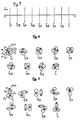
- FIG. 4 represents a series of nine sections of the assembly 100 according to the invention, that is to say of element 1.
- Each of the sections of FIG. 4 is made by a plane perpendicular to the axis , assumed to be straight, of element 1.
- Each of these sections is referenced by the letter Y followed by a number.
- the original section is referenced Y 0 and each of the other sections is referenced by the letter Y followed by a whole or fractional number which represents the ratio between on the one hand the distance separating this section from the section Y o , and d on the other hand the length of the thread winding pitch a ,, a 2 , a 3 around the axis of the element 1, that is to say the length
- Figure 5 shows the axis xx ', assumed to be straight, of element 1, and the nine sections Y o , Y 1/8 , Y 1/4 , Y 3/8 , Y 1/2 , Y 5/8 , Y 3/4 , Y 7/8 , Y 1 in Figure 4 are represented by line segments in Figure 5.
- each section of the wire of form a 3 has an arrow "f" joining the two elongated ends m l , m 2 of the wire of form a 3 , the arrow "f” being oriented from the 'end m 1 towards end m 2' and each section of the set of round wires a 1 , a 2 has an arrow "h” joining the centers of the circles a ,, a 2 of this section and oriented towards the corresponding center to wire a 1 at the center corresponding to wire a 2 , these centers not being referenced for the purpose of simplification.
- This difference in pitch allows the intermittent formation of spaces between the wires a ,, a 2 on the one hand and the wire a 3 on the other hand which allows good material migration throughout the assembly 100, with the advantages who as a result.
- One such space "e” is shown in section Y o of FIG. 4.
- FIG. 6 represents the same sections Y o , Y 1/8 , Y 1/4 , Y 3/8 , Y 1/2 , Y 5/8 , Y 3/4 , Y 7/8 .
- FIG. 7 represents another assembly 300 according to the invention constituted by a single element 3, FIG. 7 being a series of nine sections Y o , Y 1/8 , Y 1/4 , Y 3/8 , Y 1 / 2 , Y 5/8 , Y 3/4 , Y 7/8 , Y 1 performed as in Figure 4.
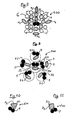
- FIG. 8 shows in section another assembly according to the invention.
- This assembly 400 consists of a single element 4 which has a core identical to the element 1 shown in Figures 1 and 4.
- the pitch P B of the layer B and the pitch P c of the layer C are defined in a similar manner to what has been said previously for the layer A.
- Each of these layers is wound around the axis of the element 4 represented by the point 0 in FIG. 8, the section of FIG. 8 being perpendicular to this axis.
- the winding pitch P c of the outer layer C is different from the winding pitch P B of the underlying layer B to avoid the interweaving of the wires of layer B with the wires of layer C, because this interweaving leads to the formation of channels capable of promoting corrosion.
- layers A and C are shaped wire layers.
- the intermediate layer B is an unsaturated layer, that is to say by definition that there exists at least one space s between two neighboring wires among the wires "b", several of these wires "b” possibly being in contact one another.
- the outer layer C is constituted alternately by a wire of form c 4 and by two round wires "c". This layer C has been shown to be unsaturated, that is to say that there exists at least one space s between two neighboring round wires "c”, but it could be saturated, all the neighboring round wires "c” then having between them continuous contact.
- the twisting pitch Pc 4 of each wire of form c 4 is different from the pitch of the winding P c of the layer C.
- the presence of the wires of form c 4 linked to the fact that the twisting pitch of these wires is different from the winding pitch of layer C allows the migration of material which can pass through this layer C and fill all the spaces inside the assembly 400 thanks to the difference in winding pitch between the outer layer C and the underlying layer B, thanks to the unsaturation of the intermediate layer B and thanks to the structure of the core 1 previously described.
- FIG. 9 shows in section another assembly 500 according to the invention.
- This assembly 500 consists of six identical strands 5 each of these strands being an element identical to the element 1 previously described and shown in Figures 1 and 4.
- the envelope of each of these strands 5 is represented by a dotted circle at Figure 9, this circle not being referenced to simplify the drawing.
- These strands 5 are arranged so that one of them, referenced 50 constitutes a core, the other five strands, referenced 5-1 constituting a layer 51 of strands 5-1 which are wound in the same direction around the the axis of the assembly 500 so as to constitute the layer 51, the section of FIG. 9 being carried out perpendicular to the axis of the assembly 500 this axis being represented by the letter Q in FIG. 9.
- FIGS. 10 and 11 each represent an assembly according to the invention with a wire of different shape from the son of shape previously described.
- FIG. 10 shows in section an assembly 600 according to the invention consisting of a single element 6 identical to the element 1 shown in Figures 1 and 4 with the difference that the form wire a 6 of this element 6 has a section practically triangular.
- FIG. 11 shows in section an assembly 700 according to the invention constituted by a single element 7 identical to element 1 with the difference that the form wire a 7 of this element 7 has a practically rectangular section.
- edges 60 of the form wire has 6 and the edges 70 of the form wire a 7 are blunt, as shown in FIGS. 10, 11, to avoid excessive stresses in the material coating the assemblies 600, 700.
- the assemblies according to the invention may each comprise several son of shape of different sections, these shape son being arranged for example in the same layer.
- At least part of the wires constituting the assemblies previously described are metallic.
- At least one layer may comprise, if desired, two or more of two adjacent shaped wires, the twisting pitch of each of the shaped wires of this layer preferably being different from the pitch of twisting of the other shaped wires which are adjacent to it in this layer, while also being different from the winding pitch of this shaped wire in this layer.
- the ratio between the largest dimension L of this section and the smallest dimension "I "in this section is greater than 1.1.
- the assemblies in accordance with the invention are advantageously used in the top of tire casings in the form, for example, of reinforcing plies, the assemblies of each ply being in particular parallel to each other and generally crossed with the assemblies of one or more other plies .
- the invention makes it possible to avoid a prepreg of the reinforcement assemblies before their incorporation into this article which they must reinforce, since it makes possible a complete migration of material inside the assemblies during molding and / or cooking of this article.
- This assembly can be impregnated almost perfectly with rubber, without the formation of empty channels capable of causing a migration of corrosive agents.
- This assembly is therefore characterized by very good corrosion resistance. It is used for example to reinforce the top of the tire envelope where it is incorporated.
- the number / of layers is at most equal to three to allow good impregnation with the coating material.
- the assemblies in accordance with the invention can be carried out with known equipment and according to known methods, this equipment and these methods not being described for the purpose of simplification.
- the shaped wires can be produced by crushing a round wire, this crushing being able to be carried out in particular with rollers.
- Such constituents may for example be a hoop and / or a core entirely constituted by a shaped wire, the pitch of twisting of this core then being different from the pitch of winding of the wires of the layer surrounding this core and the closest to this soul.
Landscapes
- Engineering & Computer Science (AREA)
- Mechanical Engineering (AREA)
- Ropes Or Cables (AREA)
- Reinforced Plastic Materials (AREA)
- Reinforcement Elements For Buildings (AREA)
- Tires In General (AREA)
- Moulding By Coating Moulds (AREA)
- Tyre Moulding (AREA)
- Package Frames And Binding Bands (AREA)
- Installation Of Indoor Wiring (AREA)
- Joining Of Building Structures In Genera (AREA)
- Yarns And Mechanical Finishing Of Yarns Or Ropes (AREA)
Claims (13)
Priority Applications (1)
| Application Number | Priority Date | Filing Date | Title |
|---|---|---|---|
| AT86105577T ATE44560T1 (de) | 1985-04-29 | 1986-04-22 | Verstaerkungsanordnung mit einer einen formdraht aufweisenden schicht; erzeugnisse mit solchen anordnungen. |
Applications Claiming Priority (2)
| Application Number | Priority Date | Filing Date | Title |
|---|---|---|---|
| FR8506874 | 1985-04-29 | ||
| FR8506874A FR2581095B1 (fr) | 1985-04-29 | 1985-04-29 | Assemblage de renfort avec une couche comportant un fil de forme; articles comportant de tels assemblages |
Publications (2)
| Publication Number | Publication Date |
|---|---|
| EP0200148A1 EP0200148A1 (de) | 1986-11-05 |
| EP0200148B1 true EP0200148B1 (de) | 1989-07-12 |
Family
ID=9319001
Family Applications (1)
| Application Number | Title | Priority Date | Filing Date |
|---|---|---|---|
| EP86105577A Expired EP0200148B1 (de) | 1985-04-29 | 1986-04-22 | Verstärkungsanordnung mit einer einen Formdraht aufweisenden Schicht; Erzeugnisse mit solchen Anordnungen |
Country Status (10)
| Country | Link |
|---|---|
| US (1) | US4709544A (de) |
| EP (1) | EP0200148B1 (de) |
| JP (1) | JPH0627203B2 (de) |
| AT (1) | ATE44560T1 (de) |
| BR (1) | BR8601920A (de) |
| CA (1) | CA1284444C (de) |
| DE (1) | DE3664347D1 (de) |
| ES (1) | ES8900115A1 (de) |
| FR (1) | FR2581095B1 (de) |
| OA (1) | OA08294A (de) |
Families Citing this family (13)
| Publication number | Priority date | Publication date | Assignee | Title |
|---|---|---|---|---|
| EP0342644B1 (de) * | 1988-05-20 | 1996-08-21 | TOYO TIRE & RUBBER CO., LTD . | Luftreifen |
| JPH02242988A (ja) * | 1989-03-15 | 1990-09-27 | Sumitomo Electric Ind Ltd | ゴム補強用スチールコード |
| US5199253A (en) * | 1990-07-16 | 1993-04-06 | American Manufacturing Company, Inc. | Nylon rope having superior friction and wearing resistance |
| US5082713A (en) * | 1990-07-23 | 1992-01-21 | Pirelli Armstrong Tire Corporation | Wide monofilament reinforcing cords employing high performance thermoplastics and tire belts made therefrom |
| DE4212846C2 (de) * | 1992-04-16 | 1997-08-14 | Sp Reifenwerke Gmbh | Verstärkungscord für elastomere Erzeugnisse |
| US5956935A (en) * | 1995-03-17 | 1999-09-28 | Tokyo Rope Manufacturing Co., Ltd. | High tensile steel filament member for rubber product reinforcement |
| US5819521A (en) * | 1995-12-28 | 1998-10-13 | Bridgestone Corporation | Steel cord for reinforcing a rubber product and pneumatic tire using the same |
| JP3411887B2 (ja) * | 1999-06-03 | 2003-06-03 | ホンドォクスチルコドゥ株式会社 | ゴム製品補強用スチールコード |
| CA2668495A1 (en) * | 2006-11-01 | 2008-05-08 | Michiel Nicolaas Van Zyl | Multi-strand steel wire rope |
| EP2475818B1 (de) * | 2009-09-11 | 2014-07-30 | NV Bekaert SA | Ovale Drahtlitze mit einem m+n Aufbau mit zumindest einem ovalen Kerndraht |
| US8677725B2 (en) * | 2009-12-07 | 2014-03-25 | Limited Liability Company “Armasteel” | Reinforcement cable |
| WO2011137337A2 (en) * | 2010-04-30 | 2011-11-03 | Schlumberger Canada Limited | Polymer-bonded metallic elements used as strength members, and/or power or data carriers in oilfield cables |
| EP2801659A1 (de) * | 2013-05-06 | 2014-11-12 | NV Bekaert SA | Metallcord mit runden und nichtrundem Filamenten |
Family Cites Families (17)
| Publication number | Priority date | Publication date | Assignee | Title |
|---|---|---|---|---|
| US586706A (en) * | 1897-07-20 | Cable-strand | ||
| US401112A (en) * | 1889-04-09 | Wire cable | ||
| US986817A (en) * | 1910-06-22 | 1911-03-14 | Thomas Gore | Wire rope or cable. |
| US1405837A (en) * | 1920-01-08 | 1922-02-07 | Roeblings John A Sons Co | Wire rope |
| FR865538A (fr) * | 1940-01-26 | 1941-05-26 | Câbles pour bandages pneumatiques | |
| US2241955A (en) * | 1940-07-16 | 1941-05-13 | Wickwire Spencer Steel Company | Metallic rope and cable |
| BE654921A (de) * | 1964-10-28 | 1965-02-15 | ||
| BE654923A (de) * | 1964-10-28 | 1965-02-15 | ||
| BE654919A (de) * | 1964-10-28 | 1965-02-15 | ||
| BE655591A (de) * | 1964-11-12 | 1965-03-01 | ||
| GB1183215A (en) * | 1967-08-29 | 1970-03-04 | Bekaert Pvba Leon | Improvements in Reinforced Articles and Reinforcing Elements therefor |
| JPS55136534A (en) * | 1979-04-13 | 1980-10-24 | Tokyo Seikou Kk | Production of steel cord |
| JPS5686802A (en) * | 1979-12-18 | 1981-07-15 | Bridgestone Corp | Pneumatic radial tire |
| NL191315C (nl) * | 1981-05-08 | 1995-05-16 | Bekaert Sa Nv | Kabel voor het versterken van elastomeer materiaal en werkwijze voor het vervaardigen van een dergelijke kabel. |
| US4506500A (en) * | 1982-04-10 | 1985-03-26 | Tokusen Kogyo Kabushiki Kaisha | Steel cord for reinforcing a rubber structure |
| LU84844A1 (de) * | 1983-06-03 | 1983-11-17 | Trefilarbed Sa | Drahtseilkonstruktion fuer elastomere erzeugnisse |
| US4544603A (en) * | 1983-08-15 | 1985-10-01 | The Goodyear Tire & Rubber Company | Reinforcing element for elastomeric articles and elastomeric articles made |
-
1985
- 1985-04-29 FR FR8506874A patent/FR2581095B1/fr not_active Expired
-
1986
- 1986-04-21 US US06/854,432 patent/US4709544A/en not_active Expired - Lifetime
- 1986-04-22 AT AT86105577T patent/ATE44560T1/de not_active IP Right Cessation
- 1986-04-22 DE DE8686105577T patent/DE3664347D1/de not_active Expired
- 1986-04-22 EP EP86105577A patent/EP0200148B1/de not_active Expired
- 1986-04-28 ES ES557854A patent/ES8900115A1/es not_active Expired
- 1986-04-28 CA CA000507739A patent/CA1284444C/fr not_active Expired - Fee Related
- 1986-04-28 JP JP61099295A patent/JPH0627203B2/ja not_active Expired - Lifetime
- 1986-04-29 BR BR8601920A patent/BR8601920A/pt not_active IP Right Cessation
- 1986-04-29 OA OA58848A patent/OA08294A/xx unknown
Also Published As
| Publication number | Publication date |
|---|---|
| FR2581095A1 (fr) | 1986-10-31 |
| FR2581095B1 (fr) | 1987-12-18 |
| JPH0627203B2 (ja) | 1994-04-13 |
| DE3664347D1 (en) | 1989-08-17 |
| CA1284444C (fr) | 1991-05-28 |
| EP0200148A1 (de) | 1986-11-05 |
| BR8601920A (pt) | 1986-12-30 |
| US4709544A (en) | 1987-12-01 |
| OA08294A (fr) | 1987-10-30 |
| JPS61250035A (ja) | 1986-11-07 |
| ATE44560T1 (de) | 1989-07-15 |
| ES8900115A1 (es) | 1988-12-16 |
| ES557854A0 (es) | 1988-12-16 |
Similar Documents
| Publication | Publication Date | Title |
|---|---|---|
| EP0200148B1 (de) | Verstärkungsanordnung mit einer einen Formdraht aufweisenden Schicht; Erzeugnisse mit solchen Anordnungen | |
| EP0172093B1 (de) | Strukturelemente aus zusammengepresstem Beton und Vorrichtung zu ihrer Herstellung | |
| EP0302784B1 (de) | Biegsame, rohrförmige Leitungen, welche unter dem Einfluss eines inneren Druckes eine konstante Länge behalten | |
| EP0204607B1 (de) | Kunststoffmast zum Tragen von insbesondere elektrischen Leitungen und Vorrichtung zum Wickeln von Fasern um diesen Mast | |
| LU84984A1 (fr) | Cables et leur procede de fabrication | |
| EP0146046B1 (de) | Verstärkungsseil bestehend ganz oder mindestens teilweise aus miteinander verseilten Litzen aus jeweils zwei Drähten; Erzeugnisse mit solchen Seilen | |
| LU83518A1 (fr) | Cables metalliques pour le renforcement de produits manufactures elastomeres | |
| WO1984002732A1 (fr) | Elements filiformes utilisables pour le renforcement de materiaux moulables en particulier pour le beton | |
| LU84130A1 (fr) | Cable en acier pour le renforcement d'une matiere elastomere,notamment pour bandages pneumatiques | |
| EP0107125A1 (de) | Schutzlage mit dreidimensionaler Struktur für die Gürtelzone eines Luftreifens | |
| EP0260556B2 (de) | Anordnung von Verstärkungsdrähten mit einem Kern für Plastik- oder Gummimaterial; mit solchen Anordnungen verstärkte Erzeugnisse | |
| FR2487264A1 (fr) | Nappe de sommet pour pneumatique et pneumatique a carcasse radiale la comportant | |
| WO2002053828A1 (fr) | Cable d'acier multicouches pour armature de sommet de pneumatique | |
| FR2546922A1 (fr) | Agencement de cables en fils metalliques pour des produits elastomeres | |
| WO2002053827A1 (fr) | Cable d'acier multicouches pour armature de sommet de pneumatique | |
| EP3890993B1 (de) | Reifen für ein tiefbaufahrzeug mit einer lagengewickelten kronenverstärkung mit metallverstärkungen | |
| FR2581094A1 (fr) | Assemblage de renfort avec une ame constituee par un fil de forme; articles comportant de tels assemblages | |
| LU84271A1 (fr) | Tringle d'armature de pneumatiques | |
| EP0118745A2 (de) | Luftreifenverstärkungseinlage bestehend aus einem Stoff mit einem dreidimensionalen Körper, Luftreifen mit solcher Verstärkung und Verfahren zur Herstellung | |
| EP1551649B1 (de) | Reifen für schwerfahrzeuge | |
| FR2635541A1 (fr) | Cable d'acier destine a renforcer des produits elastomeres | |
| EP0362570A1 (de) | Fadenverbundmaterial mit konzentrischen Fadenlagen | |
| FR2561329A1 (fr) | Gaine de guidage et de protection pour cable d'actionnement flexible, baguette de soudure et autres similaires | |
| EP2803763B1 (de) | Perfektioniertes Zug- und Hubkabel, und Herstellungsverfahren dieses Kabels | |
| FR2763280A1 (fr) | Pneumatique ayant une armature de talon constituee d'un fil de noyau et de couches de gainage |
Legal Events
| Date | Code | Title | Description |
|---|---|---|---|
| PUAI | Public reference made under article 153(3) epc to a published international application that has entered the european phase |
Free format text: ORIGINAL CODE: 0009012 |
|
| 17P | Request for examination filed |
Effective date: 19860422 |
|
| AK | Designated contracting states |
Kind code of ref document: A1 Designated state(s): AT BE CH DE FR GB IT LI LU NL SE |
|
| 17Q | First examination report despatched |
Effective date: 19880210 |
|
| GRAA | (expected) grant |
Free format text: ORIGINAL CODE: 0009210 |
|
| AK | Designated contracting states |
Kind code of ref document: B1 Designated state(s): AT BE CH DE FR GB IT LI LU NL SE |
|
| REF | Corresponds to: |
Ref document number: 44560 Country of ref document: AT Date of ref document: 19890715 Kind code of ref document: T |
|
| ITF | It: translation for a ep patent filed | ||
| REF | Corresponds to: |
Ref document number: 3664347 Country of ref document: DE Date of ref document: 19890817 |
|
| GBT | Gb: translation of ep patent filed (gb section 77(6)(a)/1977) | ||
| PLBE | No opposition filed within time limit |
Free format text: ORIGINAL CODE: 0009261 |
|
| STAA | Information on the status of an ep patent application or granted ep patent |
Free format text: STATUS: NO OPPOSITION FILED WITHIN TIME LIMIT |
|
| 26N | No opposition filed | ||
| ITTA | It: last paid annual fee | ||
| EPTA | Lu: last paid annual fee | ||
| EAL | Se: european patent in force in sweden |
Ref document number: 86105577.0 |
|
| PGFP | Annual fee paid to national office [announced via postgrant information from national office to epo] |
Ref country code: SE Payment date: 19990309 Year of fee payment: 14 |
|
| PGFP | Annual fee paid to national office [announced via postgrant information from national office to epo] |
Ref country code: LU Payment date: 19990312 Year of fee payment: 14 Ref country code: BE Payment date: 19990312 Year of fee payment: 14 |
|
| PGFP | Annual fee paid to national office [announced via postgrant information from national office to epo] |
Ref country code: NL Payment date: 19990315 Year of fee payment: 14 |
|
| PGFP | Annual fee paid to national office [announced via postgrant information from national office to epo] |
Ref country code: CH Payment date: 19990322 Year of fee payment: 14 |
|
| PGFP | Annual fee paid to national office [announced via postgrant information from national office to epo] |
Ref country code: AT Payment date: 19990419 Year of fee payment: 14 |
|
| PG25 | Lapsed in a contracting state [announced via postgrant information from national office to epo] |
Ref country code: LU Free format text: LAPSE BECAUSE OF NON-PAYMENT OF DUE FEES Effective date: 20000422 Ref country code: AT Free format text: LAPSE BECAUSE OF NON-PAYMENT OF DUE FEES Effective date: 20000422 |
|
| PG25 | Lapsed in a contracting state [announced via postgrant information from national office to epo] |
Ref country code: SE Free format text: LAPSE BECAUSE OF NON-PAYMENT OF DUE FEES Effective date: 20000423 |
|
| PG25 | Lapsed in a contracting state [announced via postgrant information from national office to epo] |
Ref country code: LI Free format text: LAPSE BECAUSE OF NON-PAYMENT OF DUE FEES Effective date: 20000430 Ref country code: CH Free format text: LAPSE BECAUSE OF NON-PAYMENT OF DUE FEES Effective date: 20000430 Ref country code: BE Free format text: LAPSE BECAUSE OF NON-PAYMENT OF DUE FEES Effective date: 20000430 |
|
| BERE | Be: lapsed |
Owner name: MICHELIN & CIE Effective date: 20000430 |
|
| PG25 | Lapsed in a contracting state [announced via postgrant information from national office to epo] |
Ref country code: NL Free format text: LAPSE BECAUSE OF NON-PAYMENT OF DUE FEES Effective date: 20001101 |
|
| EUG | Se: european patent has lapsed |
Ref document number: 86105577.0 |
|
| REG | Reference to a national code |
Ref country code: CH Ref legal event code: PL |
|
| NLV4 | Nl: lapsed or anulled due to non-payment of the annual fee |
Effective date: 20001101 |
|
| REG | Reference to a national code |
Ref country code: GB Ref legal event code: IF02 |
|
| PGFP | Annual fee paid to national office [announced via postgrant information from national office to epo] |
Ref country code: GB Payment date: 20020402 Year of fee payment: 17 |
|
| PGFP | Annual fee paid to national office [announced via postgrant information from national office to epo] |
Ref country code: FR Payment date: 20020416 Year of fee payment: 17 |
|
| PGFP | Annual fee paid to national office [announced via postgrant information from national office to epo] |
Ref country code: DE Payment date: 20020418 Year of fee payment: 17 |
|
| PG25 | Lapsed in a contracting state [announced via postgrant information from national office to epo] |
Ref country code: GB Free format text: LAPSE BECAUSE OF NON-PAYMENT OF DUE FEES Effective date: 20030422 |
|
| PG25 | Lapsed in a contracting state [announced via postgrant information from national office to epo] |
Ref country code: DE Free format text: LAPSE BECAUSE OF NON-PAYMENT OF DUE FEES Effective date: 20031101 |
|
| GBPC | Gb: european patent ceased through non-payment of renewal fee |
Effective date: 20030422 |
|
| PG25 | Lapsed in a contracting state [announced via postgrant information from national office to epo] |
Ref country code: FR Free format text: LAPSE BECAUSE OF NON-PAYMENT OF DUE FEES Effective date: 20031231 |
|
| REG | Reference to a national code |
Ref country code: FR Ref legal event code: ST |
|
| PG25 | Lapsed in a contracting state [announced via postgrant information from national office to epo] |
Ref country code: IT Free format text: LAPSE BECAUSE OF NON-PAYMENT OF DUE FEES;WARNING: LAPSES OF ITALIAN PATENTS WITH EFFECTIVE DATE BEFORE 2007 MAY HAVE OCCURRED AT ANY TIME BEFORE 2007. THE CORRECT EFFECTIVE DATE MAY BE DIFFERENT FROM THE ONE RECORDED. Effective date: 20050422 |