EP0200148B1 - Reinforcement assembly with a layer having a form wire; articles comprising such an assembly - Google Patents
Reinforcement assembly with a layer having a form wire; articles comprising such an assembly Download PDFInfo
- Publication number
- EP0200148B1 EP0200148B1 EP86105577A EP86105577A EP0200148B1 EP 0200148 B1 EP0200148 B1 EP 0200148B1 EP 86105577 A EP86105577 A EP 86105577A EP 86105577 A EP86105577 A EP 86105577A EP 0200148 B1 EP0200148 B1 EP 0200148B1
- Authority
- EP
- European Patent Office
- Prior art keywords
- layer
- threads
- shaped
- fact
- shaped thread
- Prior art date
- Legal status (The legal status is an assumption and is not a legal conclusion. Google has not performed a legal analysis and makes no representation as to the accuracy of the status listed.)
- Expired
Links
Images

Classifications
-
- D—TEXTILES; PAPER
- D07—ROPES; CABLES OTHER THAN ELECTRIC
- D07B—ROPES OR CABLES IN GENERAL
- D07B1/00—Constructional features of ropes or cables
- D07B1/06—Ropes or cables built-up from metal wires, e.g. of section wires around a hemp core
- D07B1/0606—Reinforcing cords for rubber or plastic articles
- D07B1/0613—Reinforcing cords for rubber or plastic articles the reinforcing cords being characterised by the rope configuration
-
- B—PERFORMING OPERATIONS; TRANSPORTING
- B60—VEHICLES IN GENERAL
- B60C—VEHICLE TYRES; TYRE INFLATION; TYRE CHANGING; CONNECTING VALVES TO INFLATABLE ELASTIC BODIES IN GENERAL; DEVICES OR ARRANGEMENTS RELATED TO TYRES
- B60C9/00—Reinforcements or ply arrangement of pneumatic tyres
- B60C9/005—Reinforcements made of different materials, e.g. hybrid or composite cords
-
- D—TEXTILES; PAPER
- D07—ROPES; CABLES OTHER THAN ELECTRIC
- D07B—ROPES OR CABLES IN GENERAL
- D07B2201/00—Ropes or cables
- D07B2201/10—Rope or cable structures
- D07B2201/104—Rope or cable structures twisted
-
- D—TEXTILES; PAPER
- D07—ROPES; CABLES OTHER THAN ELECTRIC
- D07B—ROPES OR CABLES IN GENERAL
- D07B2201/00—Ropes or cables
- D07B2201/20—Rope or cable components
- D07B2201/2001—Wires or filaments
- D07B2201/2002—Wires or filaments characterised by their cross-sectional shape
- D07B2201/2005—Wires or filaments characterised by their cross-sectional shape oval
-
- D—TEXTILES; PAPER
- D07—ROPES; CABLES OTHER THAN ELECTRIC
- D07B—ROPES OR CABLES IN GENERAL
- D07B2201/00—Ropes or cables
- D07B2201/20—Rope or cable components
- D07B2201/2015—Strands
- D07B2201/2022—Strands coreless
-
- D—TEXTILES; PAPER
- D07—ROPES; CABLES OTHER THAN ELECTRIC
- D07B—ROPES OR CABLES IN GENERAL
- D07B2201/00—Ropes or cables
- D07B2201/20—Rope or cable components
- D07B2201/2015—Strands
- D07B2201/2024—Strands twisted
-
- D—TEXTILES; PAPER
- D07—ROPES; CABLES OTHER THAN ELECTRIC
- D07B—ROPES OR CABLES IN GENERAL
- D07B2201/00—Ropes or cables
- D07B2201/20—Rope or cable components
- D07B2201/2015—Strands
- D07B2201/2024—Strands twisted
- D07B2201/2029—Open winding
-
- D—TEXTILES; PAPER
- D07—ROPES; CABLES OTHER THAN ELECTRIC
- D07B—ROPES OR CABLES IN GENERAL
- D07B2201/00—Ropes or cables
- D07B2201/20—Rope or cable components
- D07B2201/2015—Strands
- D07B2201/2036—Strands characterised by the use of different wires or filaments
-
- D—TEXTILES; PAPER
- D07—ROPES; CABLES OTHER THAN ELECTRIC
- D07B—ROPES OR CABLES IN GENERAL
- D07B2201/00—Ropes or cables
- D07B2201/20—Rope or cable components
- D07B2201/2047—Cores
- D07B2201/2052—Cores characterised by their structure
- D07B2201/2059—Cores characterised by their structure comprising wires
- D07B2201/2061—Cores characterised by their structure comprising wires resulting in a twisted structure
-
- Y—GENERAL TAGGING OF NEW TECHNOLOGICAL DEVELOPMENTS; GENERAL TAGGING OF CROSS-SECTIONAL TECHNOLOGIES SPANNING OVER SEVERAL SECTIONS OF THE IPC; TECHNICAL SUBJECTS COVERED BY FORMER USPC CROSS-REFERENCE ART COLLECTIONS [XRACs] AND DIGESTS
- Y10—TECHNICAL SUBJECTS COVERED BY FORMER USPC
- Y10S—TECHNICAL SUBJECTS COVERED BY FORMER USPC CROSS-REFERENCE ART COLLECTIONS [XRACs] AND DIGESTS
- Y10S57/00—Textiles: spinning, twisting, and twining
- Y10S57/902—Reinforcing or tire cords
Definitions
- the invention relates to assemblies for reinforcing materials and more particularly to assemblies intended for reinforcing plastics or rubbers.
- Such assemblies are used to produce articles which they reinforce, for example belts, pipes, plies, tire casings.
- these assemblies When these assemblies are arranged in articles, it is important that these assemblies are completely impregnated with a material, for example by the material which they must reinforce, this material penetrating into all the spaces between the wires constituting these assemblies. In fact, if this penetration is incomplete, empty channels are formed along the assemblies, and corrosive agents, for example water, liable to penetrate articles, in particular as a result of cuts, travel along these channels, which causes deterioration of the assemblies, as a result of corrosion, this deterioration leading to deterioration of the articles comprising these assemblies.
- corrosive agents for example water
- Patent BE-655,591 describes a cable made up of round wires. This cable has a surrounded by a layer consisting alternately of single wires and strands, the diameter of these single wires or of these strands being the same as that of the core, in order to better adjust the rigidity and the resistance to tiredness. This cable still has incomplete penetration of the rubber which it is intended to reinforce and its production is complex.
- the invention therefore relates to an economic reinforcement assembly to be produced which allows total impregnation with a material, for example with the material which it is intended to reinforce.
- the invention also relates to the reinforcement assembly previously defined when it is impregnated with a material, this material filling all the spaces between the wires.
- the invention also relates to articles comprising at least one reinforcement assembly according to the invention.
- FIG. 1 shows in section a reinforcement assembly 100 according to the invention.
- This assembly is constituted by a single element 1, itself constituted by a single layer of wires, this layer being referenced A.
- This layer A called “shaped wire layer”
- the round wires a 1 , a 2 are shown in black and the shape wire a 3 is shown hatched in FIG. 1.
- These three wires are wound around the axis of the element, this axis being referenced by the letter 0 in Figure 1.
- the wires a 1 , a 2 are round, that is to say that the section of each of these wires by a plane perpendicular to the axis of the wire is a circle.
- a shaped wire is a wire which has the following properties. When it is cut by any plane perpendicular to the longitudinal direction of the form wire, one obtains a section which has a center of gravity and an outline. The distance between each point of the contour and the center of gravity varies according to the position of the point on the contour.
- the wire of form a 3 of the element 1 is a wire whose section S previously defined is shown in FIG. 2.
- This section S has a center of gravity G and an outline K.
- the distance " d "between each point M of the contour K and the center of gravity G varies according to the position of the point M on the contour K.
- the section S has for example an oval shape with two extreme dimensions, a maximum dimension L and a minimum dimension" 1 ".
- the maximum dimension L corresponds to the length of the line M l M 2 joining the elongated ends M 1 , M 2 of section S and the minimum dimension "I" corresponds to the length of the line M 3 M 4 joining the ends M 3 , M 4 closest to each other in section S, these lines M 1 M 2 , M 3 M 4 passing through the center of gravity G.
- the axis of the wire of form a 3 is defined by the set of centers of gravity G when the section S moves along the wire a 3 .
- This axis is therefore shown diagrammatically by the reference G in FIG. 2.
- This axis is parallel at all points to the longitudinal direction of the shaped wire even when this axis and this direction are not rectilinear.
- the pitch for winding the wires a 1 , a 2 , a 3 of layer A is referenced P A , and it represents the pitch for winding the wires a 1 , a 2 , a 3 around the axis 0.
- , is the length of the wire winding step a 1 , a 2 , a 3 around the axis 0, that is to say the length of the step this not P A.
- This step P A is the same for the three wires a 1 , a 2 , a 3 which therefore wind around the axis 0 with the same length of step and in the same direction,
- the length of the twist pitch of the form wire a 3 is the distance, measured along the axis of the form wire a 3 , as it corresponds to a rotation of one revolution of the section S of the form wire has 3 around its axis.
- FIG. 3 represents a section S of the wire of form a 3 , the arrow F joining the two elongated ends M 1 , M 2 of the wire of form a 3 , this arrow being oriented from the end M 1 towards the end M 2 and passing through the axis of the wire a 3 .
- This axis is represented by the center of gravity G in FIG. 3.
- twist pitch Pa3 of the wire of form a 3 is an algebraic number, this pitch being positive when the twist, that is to say the rotation of the arrow F, is carried out in the direction which has been chosen arbitrarily as positive, this twisting step being negative otherwise.
- the absolute value of the twist pitch Pa3 is referenced
- the winding pitch lengths and the twist pitch lengths corresponding to the same assembly are expressed with the same unit, for example the millimeter, throughout this description.
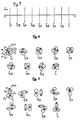
- FIG. 4 represents a series of nine sections of the assembly 100 according to the invention, that is to say of element 1.
- Each of the sections of FIG. 4 is made by a plane perpendicular to the axis , assumed to be straight, of element 1.
- Each of these sections is referenced by the letter Y followed by a number.
- the original section is referenced Y 0 and each of the other sections is referenced by the letter Y followed by a whole or fractional number which represents the ratio between on the one hand the distance separating this section from the section Y o , and d on the other hand the length of the thread winding pitch a ,, a 2 , a 3 around the axis of the element 1, that is to say the length
- Figure 5 shows the axis xx ', assumed to be straight, of element 1, and the nine sections Y o , Y 1/8 , Y 1/4 , Y 3/8 , Y 1/2 , Y 5/8 , Y 3/4 , Y 7/8 , Y 1 in Figure 4 are represented by line segments in Figure 5.
- each section of the wire of form a 3 has an arrow "f" joining the two elongated ends m l , m 2 of the wire of form a 3 , the arrow "f” being oriented from the 'end m 1 towards end m 2' and each section of the set of round wires a 1 , a 2 has an arrow "h” joining the centers of the circles a ,, a 2 of this section and oriented towards the corresponding center to wire a 1 at the center corresponding to wire a 2 , these centers not being referenced for the purpose of simplification.
- This difference in pitch allows the intermittent formation of spaces between the wires a ,, a 2 on the one hand and the wire a 3 on the other hand which allows good material migration throughout the assembly 100, with the advantages who as a result.
- One such space "e” is shown in section Y o of FIG. 4.
- FIG. 6 represents the same sections Y o , Y 1/8 , Y 1/4 , Y 3/8 , Y 1/2 , Y 5/8 , Y 3/4 , Y 7/8 .
- FIG. 7 represents another assembly 300 according to the invention constituted by a single element 3, FIG. 7 being a series of nine sections Y o , Y 1/8 , Y 1/4 , Y 3/8 , Y 1 / 2 , Y 5/8 , Y 3/4 , Y 7/8 , Y 1 performed as in Figure 4.
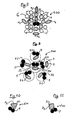
- FIG. 8 shows in section another assembly according to the invention.
- This assembly 400 consists of a single element 4 which has a core identical to the element 1 shown in Figures 1 and 4.
- the pitch P B of the layer B and the pitch P c of the layer C are defined in a similar manner to what has been said previously for the layer A.
- Each of these layers is wound around the axis of the element 4 represented by the point 0 in FIG. 8, the section of FIG. 8 being perpendicular to this axis.
- the winding pitch P c of the outer layer C is different from the winding pitch P B of the underlying layer B to avoid the interweaving of the wires of layer B with the wires of layer C, because this interweaving leads to the formation of channels capable of promoting corrosion.
- layers A and C are shaped wire layers.
- the intermediate layer B is an unsaturated layer, that is to say by definition that there exists at least one space s between two neighboring wires among the wires "b", several of these wires "b” possibly being in contact one another.
- the outer layer C is constituted alternately by a wire of form c 4 and by two round wires "c". This layer C has been shown to be unsaturated, that is to say that there exists at least one space s between two neighboring round wires "c”, but it could be saturated, all the neighboring round wires "c” then having between them continuous contact.
- the twisting pitch Pc 4 of each wire of form c 4 is different from the pitch of the winding P c of the layer C.
- the presence of the wires of form c 4 linked to the fact that the twisting pitch of these wires is different from the winding pitch of layer C allows the migration of material which can pass through this layer C and fill all the spaces inside the assembly 400 thanks to the difference in winding pitch between the outer layer C and the underlying layer B, thanks to the unsaturation of the intermediate layer B and thanks to the structure of the core 1 previously described.
- FIG. 9 shows in section another assembly 500 according to the invention.
- This assembly 500 consists of six identical strands 5 each of these strands being an element identical to the element 1 previously described and shown in Figures 1 and 4.
- the envelope of each of these strands 5 is represented by a dotted circle at Figure 9, this circle not being referenced to simplify the drawing.
- These strands 5 are arranged so that one of them, referenced 50 constitutes a core, the other five strands, referenced 5-1 constituting a layer 51 of strands 5-1 which are wound in the same direction around the the axis of the assembly 500 so as to constitute the layer 51, the section of FIG. 9 being carried out perpendicular to the axis of the assembly 500 this axis being represented by the letter Q in FIG. 9.
- FIGS. 10 and 11 each represent an assembly according to the invention with a wire of different shape from the son of shape previously described.
- FIG. 10 shows in section an assembly 600 according to the invention consisting of a single element 6 identical to the element 1 shown in Figures 1 and 4 with the difference that the form wire a 6 of this element 6 has a section practically triangular.
- FIG. 11 shows in section an assembly 700 according to the invention constituted by a single element 7 identical to element 1 with the difference that the form wire a 7 of this element 7 has a practically rectangular section.
- edges 60 of the form wire has 6 and the edges 70 of the form wire a 7 are blunt, as shown in FIGS. 10, 11, to avoid excessive stresses in the material coating the assemblies 600, 700.
- the assemblies according to the invention may each comprise several son of shape of different sections, these shape son being arranged for example in the same layer.
- At least part of the wires constituting the assemblies previously described are metallic.
- At least one layer may comprise, if desired, two or more of two adjacent shaped wires, the twisting pitch of each of the shaped wires of this layer preferably being different from the pitch of twisting of the other shaped wires which are adjacent to it in this layer, while also being different from the winding pitch of this shaped wire in this layer.
- the ratio between the largest dimension L of this section and the smallest dimension "I "in this section is greater than 1.1.
- the assemblies in accordance with the invention are advantageously used in the top of tire casings in the form, for example, of reinforcing plies, the assemblies of each ply being in particular parallel to each other and generally crossed with the assemblies of one or more other plies .
- the invention makes it possible to avoid a prepreg of the reinforcement assemblies before their incorporation into this article which they must reinforce, since it makes possible a complete migration of material inside the assemblies during molding and / or cooking of this article.
- This assembly can be impregnated almost perfectly with rubber, without the formation of empty channels capable of causing a migration of corrosive agents.
- This assembly is therefore characterized by very good corrosion resistance. It is used for example to reinforce the top of the tire envelope where it is incorporated.
- the number / of layers is at most equal to three to allow good impregnation with the coating material.
- the assemblies in accordance with the invention can be carried out with known equipment and according to known methods, this equipment and these methods not being described for the purpose of simplification.
- the shaped wires can be produced by crushing a round wire, this crushing being able to be carried out in particular with rollers.
- Such constituents may for example be a hoop and / or a core entirely constituted by a shaped wire, the pitch of twisting of this core then being different from the pitch of winding of the wires of the layer surrounding this core and the closest to this soul.
Abstract
Description
L'invention concerne les assemblages pour renforcer des matières et plus particulièrement les assemblages destinés à renforcer les matières plastiques ou les caoutchoucs.The invention relates to assemblies for reinforcing materials and more particularly to assemblies intended for reinforcing plastics or rubbers.
De tels assemblages sont utilisés pour réaliser des articles qu'ils renforcent, par exemple des courroies, des tuyaux, des nappes, des enveloppes de pneumatiques.Such assemblies are used to produce articles which they reinforce, for example belts, pipes, plies, tire casings.
Lorsque ces assemblages sont disposés dans des articles, il est important que ces assemblages soient totalement imprégnés par une matière, par exemple par la matière qu'ils doivent renforcer, cette matière pénétrant dans tous les espaces entre les fils constituant ces assemblages. En effet, si cette pénétration est incomplète, il se forme des canaux vides, le long des assemblages, et les agent corrosifs, par exemple l'eau, susceptibles de pénétrer dans les articles, notamment par suite de coupures, cheminent le long de ces canaux, ce qui provoque une détérioration des assemblages, par suite d'une corrosion, cette détérioration conduisant une détérioration des articles comportant ces assemblages.When these assemblies are arranged in articles, it is important that these assemblies are completely impregnated with a material, for example by the material which they must reinforce, this material penetrating into all the spaces between the wires constituting these assemblies. In fact, if this penetration is incomplete, empty channels are formed along the assemblies, and corrosive agents, for example water, liable to penetrate articles, in particular as a result of cuts, travel along these channels, which causes deterioration of the assemblies, as a result of corrosion, this deterioration leading to deterioration of the articles comprising these assemblies.
Divers assemblages de fils ronds ont été proposés pour tenter de permettre une bonne pénétration de matière dans tous les espaces entre les fils de ces assemblages. De tels assemblages sont, par exemple, décrits dans les brevets ou demandes de brevets publiés sous les numéros suivantes FR-2 453 933, FR-2 505 372, FR-2 456 922, US-2 900 784, US-3 273 978, US-4 506 500, BE-654 921, BE-654 923. Ces assemblages conduisent à au moins un des inconvénients suivants:
- - fabrication coûteuse à réaliser par suite de la complexité de la structure de l'assemblage;
- - pénétration encore incomplète de telle sorte que les risques de détérioration subsistent.
- - expensive manufacturing to carry out due to the complexity of the assembly structure;
- - still incomplete penetration so that the risk of deterioration remains.
Le brevet BE-655 591 décrit un câble constitué de fils ronds. Ce câble comporte une entourée d'une couche constituée alternativement de fils uniques et de torons, le diamètre de ces fils uniques ou de ces torons étant le même que celui de l'âme, dans le but de mieux régler la rigidité et la résistance à la fatigue. Ce câble présente encore une pénétration incomplète du caoutchouc qu'il est destiné à renforcer et sa réalisation est complexe.Patent BE-655,591 describes a cable made up of round wires. This cable has a surrounded by a layer consisting alternately of single wires and strands, the diameter of these single wires or of these strands being the same as that of the core, in order to better adjust the rigidity and the resistance to tiredness. This cable still has incomplete penetration of the rubber which it is intended to reinforce and its production is complex.
Il est connu d'utiliser des fils plats ou des rubans pour renforcer des articles en caoutchouc, ces fils plats ou ces rubans étant utilisés seuls, ou en âme, ou torsadés ensemble, comme décrit par exemple dans les brevets GB-1 183 215, US-3 402 546, BE-654 919, FR-865 538.It is known to use flat wires or ribbons to reinforce rubber articles, these flat wires or these ribbons being used alone, or in a core, or twisted together, as described for example in patents GB-1,183,215, US-3,402,546, BE-654,919, FR-865,538.
Ces renforts sont coûteux à réaliser et/ou ils ne permettent pas d'éviter avec certitude les problèmes de corrosion par suite d'une pénétration incomplète du caoutchouc.These reinforcements are expensive to produce and / or they do not make it possible to avoid with certainty the problems of corrosion due to incomplete penetration of the rubber.
L'invention concerne donc un assemblage de renfort économique à réaliser qui permet une imprégnation totale par une matière, par exemple par la matière qu'il est destiné à renforcer.The invention therefore relates to an economic reinforcement assembly to be produced which allows total impregnation with a material, for example with the material which it is intended to reinforce.
En conséquence, l'assemblage de renfort conforme à l'invention est caractérisé en ce qu'il est constitué au moins en partie par un élément dont les caractéristiques sont les suivantes:
- a) il comporte une seule couche de fils formant un toron ou une couche de fils formant un toron entouré par une ou deux couches de fils;
- b) au moins une couche, dite "couche fil de forme", est constituée, au moins en partie, par un fil rond et par un fil de forme;
- c) le pas de vrillage de chaque fil de forme est différent du pas de l'enroulement de ce fil de forme dans la couche où il se trouve;
- d) si l'élément comporte plus d'une couche, au moins la couche centrale est une couche à fil de forme;
- e) si l'élément comporte trois couches, le pas d'enroulement de la couche externe est différent du pas d'enroulement de la couche sous-jacente;
- f) si l'élément comporte une ou deux couches dépourvues de fils de forme, ces couches sont insaturées, c'est-à-dire qu'il existe au moins un espace entre deux fils voisin parmi les fils de ces couches.
- a) it comprises a single layer of wires forming a strand or a layer of wires forming a strand surrounded by one or two layers of wires;
- b) at least one layer, called "shaped wire layer", is formed, at least in part, by a round wire and by a shaped wire;
- c) the twisting pitch of each shaping wire is different from the pitch of the winding of this shaping wire in the layer in which it is found;
- d) if the element comprises more than one layer, at least the central layer is a shaped wire layer;
- e) if the element has three layers, the winding pitch of the outer layer is different from the winding pitch of the underlying layer;
- f) if the element comprises one or two layers devoid of shaped son, these layers are unsaturated, that is to say that there is at least one space between two neighboring son among the son of these layers.
L'invention concerne également l'assemblage de renfort précédemment défini lorsqu'il est imprégné d'une matière, cette matière remplissant tous les espaces entre les fils.The invention also relates to the reinforcement assembly previously defined when it is impregnated with a material, this material filling all the spaces between the wires.
L'invention concerne aussi les articles comportant au moins un assemblage de renfort conforme à l'invention.The invention also relates to articles comprising at least one reinforcement assembly according to the invention.
Les termes utilisés dans cette définition de l'assemblage de renfort conforme à l'invention seront expliquée en détail ultérieurement.The terms used in this definition of the reinforcement assembly according to the invention will be explained in detail later.
Les exemples qui suivent ainsi que les figures toutes schématiques du dessin correspondant à ces exemples sont destinés à illustrer l'invention et en faciliter la compréhension sans toutefois en limiter la portée.The examples which follow as well as the all schematic figures of the drawing corresponding to these examples are intended to illustrate the invention and to facilitate understanding without however limiting its scope.
Sur le dessin:
- - la figure 1 représente en coupe un assemblage de renfort conforme à l'invention constitué par un seul élément comportant un fil de forme;
- - les figures 2 et 3 représentent chacune une section du fil de forme de l'assemblage de renfort représenté à la figure 1 ;
- - la figure 4 représente une série de coupes de l'assemblage de renfort représenté à la figure 1;
- - la figure 5 représente la disposition des coupes de la figure 4 par rapport à l'axe de l'élément représenté à la figure 1;
- - la figure 6 représente une série de coupes d'un assemblage de renfort qui n'est pas conforme à l'invention;
- - la figure 7 représente une série de coupes d'un autre assemblage de renfort conforme à l'invention;
- - les figures 8, 9, 10, 11 représentent chacune en coupe un autre assemblage de renfort conforme à l'invention.
- - Figure 1 shows in section a reinforcement assembly according to the invention consisting of a single element comprising a form wire;
- - Figures 2 and 3 each show a section of the form wire of the reinforcement assembly shown in Figure 1;
- - Figure 4 shows a series of sections of the reinforcement assembly shown in Figure 1;
- - Figure 5 shows the arrangement of the sections of Figure 4 relative to the axis of the element shown in Figure 1;
- - Figure 6 shows a series of sections of a reinforcement assembly which is not in accordance with the invention;
- - Figure 7 shows a series of sections of another reinforcement assembly according to the invention;
- - Figures 8, 9, 10, 11 each show in section another reinforcement assembly according to the invention.
La figure 1 représente en coupe un assemblage de renfort 100 conforme à l'invention. Cet assemblage est constitué par un seul élément 1, lui- même constitué par une seule couche de fils, cette couche étant référencée A. Cette couche A dite "couche à fil de forme", est constituée par trois fils, deux fils ronds a1, a2 et un fil de forme a3. Pour la clarté du dessin, les fils ronds a1, a2 sont représentés en noir et le fil de forme a3 est représenté hachuré à la figure 1. Ces trois fils s'enroulent autour de l'axe de l'élément, cet axe étant référencé par la lettre 0 à la figure 1.Figure 1 shows in section a
Les fils a1, a2 sont ronds, c'est-à-dire que la section de chacun de ces fils par un plan perpendiculaire à l'axe du fil est un cercle. Par définition, un fil de forme est un fil qui a les propriétés suivantes. Lorsqu'on le coupe par un plan quelconque perpendiculaire à la direction longitudinale du fil de forme, on obtient une section qui a un centre de gravité et un contour. La distance entre chaque point du contour et le centre de gravité varie suivant la position du point sur le contour.The wires a 1 , a 2 are round, that is to say that the section of each of these wires by a plane perpendicular to the axis of the wire is a circle. By definition, a shaped wire is a wire which has the following properties. When it is cut by any plane perpendicular to the longitudinal direction of the form wire, one obtains a section which has a center of gravity and an outline. The distance between each point of the contour and the center of gravity varies according to the position of the point on the contour.
A titre d'exemple, le fil de forme a3 de l'élément 1 est un fil dont la section S précédemment définie est représentée à la figure 2. Cette section S a un centre de gravité G et un contour K. La distance "d" entre chaque point M du contour K et le centre de gravité G varie suivant la position du point M sur le contour K. La section S a par exemple une forme ovale avec deux dimensions extrêmes, une dimension maximum L et une dimension minimum "1". La dimension maximum L correspond à la longueur de la ligne MlM2 joignant les extrémités allongées M1, M2 de la section S et la dimension minimum "I" correspond à la longueur de la ligne M3M4 joignant les extrémités M3, M4 les plus proches entre elles de la section S, ces lignes M1M2, M3M4 passant par le centre de gravité G.By way of example, the wire of form a 3 of the
L'axe du fil de forme a3 est défini par l'ensemble des centres de gravité G lorsque la section S se déplace le long du fil a3. Cet axe est donc schématisé par la référence G à la figure 2. Cet axe est parallèle en tout point à la direction longitudinale du fil de forme même lorsque cet axe et cette direction ne sont pas rectilignes. Le pas d'enroulement des fils a1, a2, a3 de la couche A est référencé PA, et il représente le pas d'enroulement des fils a1, a2, a3 autour de l'axe 0. Ce pas est un nombre algébrique, il est positif lorsque l'enroulement s'effectue dans un sens choisi arbitrairement comme positif, par exemple l'enroulement à droite, et négatif dans le cas inverse. La valeur absolue de ce pas, référencée |PA|, est la longueur du pas d'enroulement des fils a1, a2, a3 autour de l'axe 0, c'est-à-dire la longueur du pas ce pas PA. Ce pas PA est le même pour les trois fils a1, a2, a3 qui s'enroulent donc autour de l'axe 0 avec la même longueur de pas et dans le même sens, |PA| étant mesuré le long de l'axe 0 supposé rectiligne.The axis of the wire of form a 3 is defined by the set of centers of gravity G when the section S moves along the wire a 3 . This axis is therefore shown diagrammatically by the reference G in FIG. 2. This axis is parallel at all points to the longitudinal direction of the shaped wire even when this axis and this direction are not rectilinear. The pitch for winding the wires a 1 , a 2 , a 3 of layer A is referenced P A , and it represents the pitch for winding the wires a 1 , a 2 , a 3 around the
La longueur du pas de vrillage du fil de forme a3 est la distance, mesurée le long de l'axe du fil de forme a3, telle qu'elle correspond à une rotation d'un tour de la section S du fil de forme a3 autour de son axe. La figure 3 représente une section S du fil de forme a3, la flèche F joignant les deux extrémités allongées M1, M2 du fil de forme a3, cette flèche étant orientée de l'extrémité M1 vers l'extrémité M2 et passant par l'axe du fil a3. Cet axe est représenté par le centre de gravité G à la figure 3. Lorsque la distance mesurée le long de l'axe du fil de forme a3 est égale à la longueur du pas de vrillage, la flèche F effectue une rotation d'un tour autour de cet axe. Le pas de vrillage Pa3 du fil de forme a3 est un nombre algébrique, ce pas étant positif lorsque le vrillage, c'est-à-dire la rotation de la flèche F, s'effectue dans le sens qui a été choisi arbitrairement comme positif, ce pas de vrillage étant négatif dans le cas contraire.The length of the twist pitch of the form wire a 3 is the distance, measured along the axis of the form wire a 3 , as it corresponds to a rotation of one revolution of the section S of the form wire has 3 around its axis. FIG. 3 represents a section S of the wire of form a 3 , the arrow F joining the two elongated ends M 1 , M 2 of the wire of form a 3 , this arrow being oriented from the end M 1 towards the end M 2 and passing through the axis of the wire a 3 . This axis is represented by the center of gravity G in FIG. 3. When the distance measured along the axis of the form wire a 3 is equal to the length of the twisting pitch, the arrow F performs a rotation of one turn around this axis. The twist pitch Pa3 of the wire of form a 3 is an algebraic number, this pitch being positive when the twist, that is to say the rotation of the arrow F, is carried out in the direction which has been chosen arbitrarily as positive, this twisting step being negative otherwise.
La valeur absolue du pas de vrillage Pa3 est référencée |Pa3| et elle correspond à la longueur du pas de vrillage Pa3. Les longueurs de pas d'enroulement et les longueurs de pas de vrillage correspondant à un même assemblage sont exprimés avec la même unité, par exemple le millimètre, dans toute cette description.The absolute value of the twist pitch Pa3 is referenced | Pa 3 | and it corresponds to the length of the twist pitch Pa3. The winding pitch lengths and the twist pitch lengths corresponding to the same assembly are expressed with the same unit, for example the millimeter, throughout this description.
La figure 4 représente une série de neuf coupes de l'assemblage 100 conforme à l'invention, c'est-à-dire de l'élément 1. Chacune des coupes de la figure 4 est effectuée par un plan perpendiculaire à l'axe, supposé rectiligne, de l'élément 1. Chacune de ces coupes est référencée par la lettre Y suivie d'un nombre. La coupe d'origine est référencée Y0 et chacune des autres coupes est référencée par la lettre Y suivie d'un nombre entier ou fractionnaire qui représente le rapport entre d'une part la distance séparant cette coupe de la coupe Yo, et d'autre part la longueur du pas d'enroulement des fils a,, a2, a3 autour de l'axe de l'élément 1, c'est-à-dire la longueur |PA| du pas PA' FIG. 4 represents a series of nine sections of the
La figure 5 représente l'axe xx', supposé rectiligne, de l'élément 1, et les neuf coupes Yo, Y1/8, Y1/4, Y3/8, Y1/2, Y5/8, Y3/4, Y7/8, Y1 de la figure 4 sont représentées par des segments de droite à la figure 5.Figure 5 shows the axis xx ', assumed to be straight, of
Toutes les coupes de la figure 4 sont regardées dans le même sens qui est le sens de la flèche V et le nombre qui suit la lettre Y augmente dans le sens de la flèche V, à la figure 5.All the sections in Figure 4 are viewed in the same direction which is the direction of the arrow V and the number following the letter Y increases in the direction of the arrow V, in Figure 5.
A titre d'exemple, la distance séparant les coupes Y1 et Yo est égale à la longueur |PA|. Pour la clarté du dessin à la figure 4, chaque section du fil de forme a3 comporte une flèche "f" joignant les deux extrémités allongées ml, m2 du fil de forme a3, la flèche "f" étant orientée de l'extrémité m1 vers l'extrémité m2' et chaque section de l'ensemble des fils ronds a1, a2 comporte une flèche "h" joignant les centres des cercles a,, a2 de cette section et orientée du centre correspondant au fil a1 au centre correspondant au fil a2, ces centres n'étant pas référencés dans un but de simplification.For example, the distance separating the sections Y 1 and Y o is equal to the length | P A |. For clarity of the drawing in FIG. 4, each section of the wire of form a 3 has an arrow "f" joining the two elongated ends m l , m 2 of the wire of form a 3 , the arrow "f" being oriented from the 'end m 1 towards end m 2' and each section of the set of round wires a 1 , a 2 has an arrow "h" joining the centers of the circles a ,, a 2 of this section and oriented towards the corresponding center to wire a 1 at the center corresponding to wire a 2 , these centers not being referenced for the purpose of simplification.
Conformément à l'invention, les pas PA et Pa3 sont différents. Ces pas sont par exemple reliés par la relation: PA = - Pa3, c'est-à-dire que le vrillage s'effectue en sens inverse de l'enroulement des fils a1, a2, a3, la longueur IPAI du pas d'enroulement étant égale à la longueur |Pa3| du pas de vrillage.According to the invention, the steps P A and Pa3 are different. These steps are for example linked by the relation: P A = - Pa3, that is to say that the twisting is carried out in the opposite direction from the winding ment of the wires a 1 , a 2 , a 3 , the length IP AI of the winding pitch being equal to the length | Pa 3 | no twisting.
Cette différence de pas permet la formation intermittente d'espaces entre les fils a,, a2 d'une part et le fil a3 d'autre part ce qui permet une bonne migration de matière dans tout l'assemblage 100, avec les avantages qui en découlent. On tel espace "e" est représenté à la coupe Yo de la figure 4.This difference in pitch allows the intermittent formation of spaces between the wires a ,, a 2 on the one hand and the wire a 3 on the other hand which allows good material migration throughout the
A titre de comparaison, la figure 6 représente les mêmes coupes Yo, Y1/8, Y1/4, Y3/8, Y1/2, Y5/8, Y3/4, Y7/8. Y1 pour un assemblage 200 non conforme à l'invention et constitué par un seul élément 2 identique à l'élément 1, mais avec la différence que l'on a la relation: PA = Pa3.By way of comparison, FIG. 6 represents the same sections Y o , Y 1/8 , Y 1/4 , Y 3/8 , Y 1/2 , Y 5/8 , Y 3/4 , Y 7/8 . Y 1 for an assembly 200 not in accordance with the invention and consisting of a single element 2 identical to
On voit sur cette figure 6 que les fils a1, a2, a3 sont toujours au contact entre eux. Il y a donc formation d'un canal "t" entre les trois fils a1, a2, a3. Ce canal "t" reste vide après imprégnation de l'assemblage 200 avec une matière qui ne peut pas pénétrer dans ce canal. Ce canal "t" est donc susceptible de permettre ultérieurement la migration d'agents corrosifs, par exemple l'eau, le long de l'assemblage 200 avec les inconvénients qui en découlent, notamment les risques de corrosion.It can be seen in this FIG. 6 that the wires a 1 , a 2 , a 3 are always in contact with each other. There is therefore the formation of a channel "t" between the three wires a 1 , a 2 , a 3 . This channel "t" remains empty after impregnation of the assembly 200 with a material which cannot penetrate this channel. This channel "t" is therefore capable of subsequently allowing the migration of corrosive agents, for example water, along the assembly 200 with the drawbacks which result therefrom, in particular the risks of corrosion.
La figure 7 représente un autre assemblage 300 conforme à l'invention constitué par un seul élément 3, la figure 7 étant une série de neuf coupes Yo, Y1/8, Y1/4, Y3/8, Y1/2, Y5/8, Y3/4, Y7/8, Y1 effectuées comme à la figure 4. L'élément 3 est identique à l'élément 1 représenté à la figure 4 avec la différence qu'on a la relation: PA = 2 Pa3, c'est-à-dire que le sens de vrillage du fil de forme a3 est le même que le sens de l'enroulemert des fils a1, a2, a3 dans la couche A, mais que la longueur |PA| du pas d'enroulement de cette couche A est double de la longueur du pas de vrillage du fil de forme a3.FIG. 7 represents another
Pour la clarté du dessin, les indices correspondant aux assemblages 100, 200, 300 ne sont portés que sur les coupes Yo des figures 4, 6, 7.For clarity of the drawing, the indices corresponding to the
La figure 8 représente en coupe un autre assemblage conforme à l'invention. Cet assemblage 400 est constitué par un seul élément 4 qui comporte une âme identique à l'élément 1 représenté aux figures 1 et 4. Autour de la couche centrale A formée par cette 1, se trouve une couche B de huit fils ronds "b", cette couche B étant dépourvue de fil de forme, et une couche externe C disposée autour de la couche B, cette couche externe C étant constituée par huit fils ronds "c" et quatre fils de forme c4. Le pas PB de la couche B et le pas Pc de la couche C sont définis de façon analogue à ce qui a été dit précédemment pour la couche A. Chacune de ces couches s'enroule autour de l'axe de l'élément 4 représenté par le point 0 à la figure 8, la coupe de la figure 8 étant perpendiculaire à cet axe. Le pas d'enroulement Pc de la couche externe C est différent du pas d'enroulement PB de la couche B sous-jacente pour éviter l'imbrication des fils de la couche B avec les fils de la couche C, car cette imbrication conduit à la formation de canaux susceptible de favoriser la corrosion. Dans l'assemblage 400 les couches A et C sont des couches à fil de forme.Figure 8 shows in section another assembly according to the invention. This
La couche intermédiaire B est une couche insaturée, c'est-à-dire par définition qu'il existe au moins un espace s entre deux fils voisins parmi les fils "b", plusieurs de ces fils "b" pouvant être éventuellement au contact les uns des autres. La couche externe C est constituée alternativement par un fil de forme c4 et par deux fils ronds "c". Cette couche C a été représentée insaturée, c'est-à-dire qu'il existe au moins un espace s centre deux fils ronds "c" voisins, mais elle pourrait être saturée, tous les fils ronds "c" voisins ayant alors entre eux un contact continu.The intermediate layer B is an unsaturated layer, that is to say by definition that there exists at least one space s between two neighboring wires among the wires "b", several of these wires "b" possibly being in contact one another. The outer layer C is constituted alternately by a wire of form c 4 and by two round wires "c". This layer C has been shown to be unsaturated, that is to say that there exists at least one space s between two neighboring round wires "c", but it could be saturated, all the neighboring round wires "c" then having between them continuous contact.
Conformément à l'invention, le pas de vrillage Pc4 de chaque fil de forme c4 est différent du pas de l'enroulement Pc de la couche C. La présence des fils de forme c4 liée au fait que le pas de vrillage de ces fils est différent du pas d'enroulement de la couche C permet la migration de matière qui peut traverser cette couche C et remplir tous les espaces à l'intérieur de l'assemblage 400 grâce à la différence de pas d'enroulement entre la couche externe C et la couche sous-jacente B, grâce à l'insaturation de la couche intermédiaire B et grâce à la structure de l'âme 1 précédemment décrite.According to the invention, the twisting pitch Pc 4 of each wire of form c 4 is different from the pitch of the winding P c of the layer C. The presence of the wires of form c 4 linked to the fact that the twisting pitch of these wires is different from the winding pitch of layer C allows the migration of material which can pass through this layer C and fill all the spaces inside the
La figure 9 représente en coupe un autre assemblage 500 conforme à l'invention. Cet assemblage 500 est constitué par six torons identiques 5 chacun de ces torons étant un élément identique à l'élément 1 précédemment décrit et représenté aux figures 1 et 4. L'enveloppe de chacun de ces torons 5 est représentée par un cercle en pointillés à la figure 9, ce cercle n'étant pas référencé pour simplifier le dessin. Ces torons 5 sont disposés de telle sorte que l'un d'eux, référencé 50 constitue une âme, les cinq autres torons, référencées 5-1 constituant une couche 51 de torons 5-1 qui sont enroulés dans le même sens autour de l'axe de l'assemblage 500 de façon à constituer la couche 51, la coupe de la figure 9 étant effectuée perpendiculairement à l'axe de l'assemblage 500 cet axe étant représenté par la lettre Q à la figure 9.Figure 9 shows in section another
L'invention n'est pas limitée aux cas où les fils de forme des assemblages conformes à l'invention ont une section ovale. A titre d'exemple, les figures 10 et 11 représentent chacune un assemblage conforme à l'invention avec un fil de forme différent des fils de forme précédemment décrits.The invention is not limited to cases where the form wires of the assemblies according to the invention have an oval section. By way of example, FIGS. 10 and 11 each represent an assembly according to the invention with a wire of different shape from the son of shape previously described.
La figure 10 représente en coupe un assemblage 600 conforme à l'invention constitué par un seul élément 6 identique à l'élément 1 représenté aux figures 1 et 4 avec la différence que le fil de forme a6 de cet élément 6 a une section pratiquement triangulaire.10 shows in section an
La figure 11 représente en coupe un assemblage 700 conforme à l'invention constitué par un seul élément 7 identique à l'élément 1 avec la différence que le fil de forme a7 de cet élément 7 a une section pratiquement rectangulaire.FIG. 11 shows in section an
De préférence, les bords 60 du fil de forme a6 et les bords 70 du fil de forme a7 sont émoussés, comme représenté aux figures 10, 11, pour éviter des contraintes excessives dans la matière enrobant les assemblages 600, 700.Preferably, the
Les coupes des figures 1, 4, 6 à 8, 10, 11 sont effectuées chacune par un plan perpendiculaire à l'axe de l'élément.The sections of Figures 1, 4, 6 to 8, 10, 11 are each made by a plane perpendicular to the axis of the element.
Les assemblages conformes à l'invention peuvent comporter chacun plusieurs fils de forme de sections différentes, ces fils de forme étant disposés par exemple dans une même couche.The assemblies according to the invention may each comprise several son of shape of different sections, these shape son being arranged for example in the same layer.
De préférence, au moins une partie des fils constituant les assemblages précédemment décrits sont métalliques.Preferably, at least part of the wires constituting the assemblies previously described are metallic.
Dans un assemblage conforme à l'invention, au moins une couche peut comporter, si on le désire, deux ou plus de deux fils de forme adjacents le pas de vrillage de chacun des fils de forme de cette couche étant de préférence différent du pas de vrillage des autres fils de forme qui lui sont adjacents dans cette couche, tout en étant, aussi, différent du pas d'enroulement de ce fil de forme dans cette couche.In an assembly according to the invention, at least one layer may comprise, if desired, two or more of two adjacent shaped wires, the twisting pitch of each of the shaped wires of this layer preferably being different from the pitch of twisting of the other shaped wires which are adjacent to it in this layer, while also being different from the winding pitch of this shaped wire in this layer.
De préférence, pour chaque fil de forme d'un assemblage conforme à l'invention, dans toute section perpendiculaire à la direction longitudinale de ce fil de forme, le rapport entre la plus grande dimension L de cette section et la plus petite dimension "I" de cette section est supérieur à 1,1.Preferably, for each form wire of an assembly according to the invention, in any section perpendicular to the longitudinal direction of this form wire, the ratio between the largest dimension L of this section and the smallest dimension "I "in this section is greater than 1.1.
Les assemblages conformes l'invention sont avantageusement utilisés dans le sommet des enveloppes de pneumatiques sous forme par exemple de nappes de renfort, les assemblages de chaque nappe étant notamment parallèles entre eux et en général croisés avec les assemblages d'une ou de plusieurs autres nappes.The assemblies in accordance with the invention are advantageously used in the top of tire casings in the form, for example, of reinforcing plies, the assemblies of each ply being in particular parallel to each other and generally crossed with the assemblies of one or more other plies .
Dans le cas d'un article en caoutchouc, par exemple une enveloppe de pneumatique, l'invention permet d'éviter une préimprégnation des assemblages de renfort avant leur incorporation dans cet article qu'ils doivent renforcer, car elle rend possible une migration complète de matière à l'intérieur des assemlages lors du moulage et/ou de la cuisson de cet article.In the case of a rubber article, for example a tire, the invention makes it possible to avoid a prepreg of the reinforcement assemblies before their incorporation into this article which they must reinforce, since it makes possible a complete migration of material inside the assemblies during molding and / or cooking of this article.
A titre d'exemple, on réalise un assemblage conforme à l'invention dont la constitution est la suivante. Il est entièrement constitué par deux couches de fils qui sont tous en acier.
- - Une couche centrale A servant d'âme et analogue à l'élément 1 précédemment décrit, cette couche A étant constituée par deux fils ronds, de diamètre 0,350 mm et un fil de forme dont la section est analogue à celle du fil de forme A3 représenté à la figure 2 avec les valeurs suivantes: L = 0,390 mm et 1 = 0,290 mm, c'est-à-dire qu'on a la relation L/I = 1,34; les trois fils de cette couche A sont enroulés vers la gauche avec une longueur de pas de 10 mm; le vrillage du fil de forme s'effectue vers la gauche, donc dans le même sens que l'enroulage des fils de la couche A, mais avec une longueur de pas de 7 mm, c'est-à-dire que le pas de vrillage de ce fil de forme est différent de son pas d'enroulement dans la couche A.
- - Une couche externe B insaturée constituée par huit fils ronds de diamètre 0,350 mm, les fils de cette couche B étant enroulés vers la gauche avec une longueur de pas de 15 mm.
- - A central layer A serving as a core and similar to the
element 1 described above, this layer A consisting of two round wires, of diameter 0.350 mm and a shaped wire whose section is similar to that of the form A wire 3 represented in FIG. 2 with the following values: L = 0.390 mm and 1 = 0.290 mm, that is to say that we have the relation L / I = 1.34; the three wires of this layer A are wound to the left with a pitch length of 10 mm; twisting of the shaped wire is carried out to the left, therefore in the same direction as the winding of the wires of layer A, but with a pitch length of 7 mm, that is to say that the pitch of twisting of this shaped wire is different from its winding pitch in layer A. - - An unsaturated outer layer B consisting of eight round wires of diameter 0.350 mm, the wires of this layer B being wound to the left with a pitch length of 15 mm.
Cet assemblage peut être imprégné de façon pratiquement parfaite par du caoutchouc, sans formation de canaux vides susceptibles de provoquer une migration d'agents corrosifs.This assembly can be impregnated almost perfectly with rubber, without the formation of empty channels capable of causing a migration of corrosive agents.
Cet assemblage se caractérise donc par une très bonne résistance à la corrosion. Il est utilisé par exemple pour renforcer le sommet de l'enveloppe de pneumatique où il est incorporé.This assembly is therefore characterized by very good corrosion resistance. It is used for example to reinforce the top of the tire envelope where it is incorporated.
Dans les assemblages conformes à l'invention, le nombre/de couches est au plus égal à trois pour permettre une bonne imprégnation par la matière d'enrobage.In the assemblies according to the invention, the number / of layers is at most equal to three to allow good impregnation with the coating material.
De préférence, dans les assemblages conformes à l'invention, on a les relations suivantes:
- - Dans chaque couche à fil de forme, le nombre de fils de forme est au plus égal à Ï4, N étant le nombre total de fils dans la couche considérée (c'est-à-dire le nombre total: fils ronds + fils de forme). On favorise ainsi une répartition homogène des efforts dans l'assemblage et on diminue le coût. Avantageusement le nombre de fils de forme, dans chaque couche à fil de forme, est au plus égal à N/2.
- - Lorsque l'assemblage conforme à l'invention comporte au moins une couche insaturée dépourvue de fil de forme, le rapport ε/Ø est au moins égal à 0,06 dans chacune de ces couches, s étant l'espace entre deux fils voisins, 0 étant le diamètre des fils de cette couche, supposé le même pour tous ces fils, les espaces étant supposés répartis régulièrement entre tous les fils de cette couche, c'est-à-dire que la valeur s de ce rapport représente un espace moyen. On tel espace moyen e et le diamètre 0 sont représentés à la figure 8, pour la couche B insaturée de l'assemblage 400 représenté sur cette figure.
- - Lorsque, dans une couche à fil de forme, le vrillage du fil de forme s'effectue dans le même sens que l'enroulement de ce fil de forme dans la couche, le rapport

est, pour ce fil de forme, au moins égal à 0,2 en valeur absolue.
- - In each layer of shaped wire, the number of shaped wires is at most equal to 4, N being the total number of wires in the layer considered (that is to say the total number: round wires + son of form). This promotes a uniform distribution of forces in the assembly and reduces the cost. Advantageously, the number of shaped wires, in each shaped wire layer, is at most equal to N / 2.
- - When the assembly according to the invention comprises at least one unsaturated layer devoid of shaped wire, the ratio ε / Ø is at least equal to 0.06 in each of these layers, s being the space between two neighboring wires , 0 being the diameter of the wires of this layer, assumed to be the same for all these wires, the spaces being assumed to be distributed regularly among all the wires of this layer, that is to say that the value s of this ratio represents a space way. One such mean space e and the
diameter 0 are shown in FIG. 8, for the unsaturated layer B of theassembly 400 shown in this figure. - - When, in a shaped wire layer, the twisting of the shaped wire takes place in the same direction as the winding of this shaped wire in the layer, the ratio
is, for this shaped wire, at least equal to 0.2 in absolute value.
Les assemblages conformes à l'invention peuvent être réalisés avec des équipements connus et selon des procédés connus, ces équipements et ces procédés n'étant pas décrits dans un but de simplification. C'est ainsi par exemple que les fils de forme peuvent être réalisés en écrasant un fil rond, cet écrasement pouvant être réalisé notamment avec des rouleaux.The assemblies in accordance with the invention can be carried out with known equipment and according to known methods, this equipment and these methods not being described for the purpose of simplification. Thus, for example, the shaped wires can be produced by crushing a round wire, this crushing being able to be carried out in particular with rollers.
Bien entendu, l'invention n'est pas limitée aux exemples de réalisation précédemment décrits. C'est ainsi par exemple que les assemblages conformes à l'invention peuvent comporter d'autres constituants que les éléments précédemment décrits.Of course, the invention is not limited to the embodiments previously described. This is how, for example, in accordance with the invention may comprise other constituents than the elements described above.
De tels constituants peuvent être par exemple une frette et/ou une âme entièrement constituée par un fil de forme, le pas de vrillage de cette âme étant alors différent du pas d'enroulement des fils de la couche entourant cette âme et la plus proche de cette âme.Such constituents may for example be a hoop and / or a core entirely constituted by a shaped wire, the pitch of twisting of this core then being different from the pitch of winding of the wires of the layer surrounding this core and the closest to this soul.
Claims (13)
for this shaped thread is at least equal to 0.2 in absolute value.
Priority Applications (1)
| Application Number | Priority Date | Filing Date | Title |
|---|---|---|---|
| AT86105577T ATE44560T1 (en) | 1985-04-29 | 1986-04-22 | REINFORCEMENT ASSEMBLY WITH A LAYER COMPOSING A FORM WIRE; PRODUCTS WITH SUCH ARRANGEMENTS. |
Applications Claiming Priority (2)
| Application Number | Priority Date | Filing Date | Title |
|---|---|---|---|
| FR8506874A FR2581095B1 (en) | 1985-04-29 | 1985-04-29 | REINFORCEMENT ASSEMBLY WITH A LAYER HAVING A SHAPE WIRE; ARTICLES COMPRISING SUCH ASSEMBLIES |
| FR8506874 | 1985-04-29 |
Publications (2)
| Publication Number | Publication Date |
|---|---|
| EP0200148A1 EP0200148A1 (en) | 1986-11-05 |
| EP0200148B1 true EP0200148B1 (en) | 1989-07-12 |
Family
ID=9319001
Family Applications (1)
| Application Number | Title | Priority Date | Filing Date |
|---|---|---|---|
| EP86105577A Expired EP0200148B1 (en) | 1985-04-29 | 1986-04-22 | Reinforcement assembly with a layer having a form wire; articles comprising such an assembly |
Country Status (10)
| Country | Link |
|---|---|
| US (1) | US4709544A (en) |
| EP (1) | EP0200148B1 (en) |
| JP (1) | JPH0627203B2 (en) |
| AT (1) | ATE44560T1 (en) |
| BR (1) | BR8601920A (en) |
| CA (1) | CA1284444C (en) |
| DE (1) | DE3664347D1 (en) |
| ES (1) | ES8900115A1 (en) |
| FR (1) | FR2581095B1 (en) |
| OA (1) | OA08294A (en) |
Families Citing this family (13)
| Publication number | Priority date | Publication date | Assignee | Title |
|---|---|---|---|---|
| DE68926978T2 (en) * | 1988-05-20 | 1997-04-03 | Toyo Tire & Rubber Co | tire |
| JPH02242988A (en) * | 1989-03-15 | 1990-09-27 | Sumitomo Electric Ind Ltd | Steel cord for reinforcing rubber |
| US5199253A (en) * | 1990-07-16 | 1993-04-06 | American Manufacturing Company, Inc. | Nylon rope having superior friction and wearing resistance |
| US5082713A (en) * | 1990-07-23 | 1992-01-21 | Pirelli Armstrong Tire Corporation | Wide monofilament reinforcing cords employing high performance thermoplastics and tire belts made therefrom |
| DE4212846C2 (en) * | 1992-04-16 | 1997-08-14 | Sp Reifenwerke Gmbh | Reinforcement cord for elastomeric products |
| US5956935A (en) * | 1995-03-17 | 1999-09-28 | Tokyo Rope Manufacturing Co., Ltd. | High tensile steel filament member for rubber product reinforcement |
| US5819521A (en) * | 1995-12-28 | 1998-10-13 | Bridgestone Corporation | Steel cord for reinforcing a rubber product and pneumatic tire using the same |
| JP3411887B2 (en) * | 1999-06-03 | 2003-06-03 | ホンドォクスチルコドゥ株式会社 | Steel cord for reinforcing rubber products |
| AU2007315696A1 (en) * | 2006-11-01 | 2008-05-08 | Michiel Nicolaas Van Zyl | Multi-strand steel wire rope |
| CN102482844B (en) * | 2009-09-11 | 2015-08-12 | 贝卡尔特公司 | With the oval steel cable of oval wire |
| JP2013513038A (en) * | 2009-12-07 | 2013-04-18 | アルモン リミティド | Reinforced cable |
| US9248473B2 (en) | 2010-04-30 | 2016-02-02 | Schlumberger Technology Corporation | Polymer-bonded metallic elements used as strength members, and/or power or data carriers in oilfield cables |
| EP2801659A1 (en) * | 2013-05-06 | 2014-11-12 | NV Bekaert SA | Metal cord with round and non-round filaments |
Family Cites Families (17)
| Publication number | Priority date | Publication date | Assignee | Title |
|---|---|---|---|---|
| US401112A (en) * | 1889-04-09 | Wire cable | ||
| US586706A (en) * | 1897-07-20 | Cable-strand | ||
| US986817A (en) * | 1910-06-22 | 1911-03-14 | Thomas Gore | Wire rope or cable. |
| US1405837A (en) * | 1920-01-08 | 1922-02-07 | Roeblings John A Sons Co | Wire rope |
| FR865538A (en) * | 1940-01-26 | 1941-05-26 | Cables for pneumatic tires | |
| US2241955A (en) * | 1940-07-16 | 1941-05-13 | Wickwire Spencer Steel Company | Metallic rope and cable |
| BE654921A (en) * | 1964-10-28 | 1965-02-15 | ||
| BE654923A (en) * | 1964-10-28 | 1965-02-15 | ||
| BE654919A (en) * | 1964-10-28 | 1965-02-15 | ||
| BE655591A (en) * | 1964-11-12 | 1965-03-01 | ||
| GB1183215A (en) * | 1967-08-29 | 1970-03-04 | Bekaert Pvba Leon | Improvements in Reinforced Articles and Reinforcing Elements therefor |
| JPS55136534A (en) * | 1979-04-13 | 1980-10-24 | Tokyo Seikou Kk | Production of steel cord |
| JPS5686802A (en) * | 1979-12-18 | 1981-07-15 | Bridgestone Corp | Pneumatic radial tire |
| NL191315C (en) * | 1981-05-08 | 1995-05-16 | Bekaert Sa Nv | Cable for reinforcing elastomeric material and method for manufacturing such a cable. |
| US4506500A (en) * | 1982-04-10 | 1985-03-26 | Tokusen Kogyo Kabushiki Kaisha | Steel cord for reinforcing a rubber structure |
| LU84844A1 (en) * | 1983-06-03 | 1983-11-17 | Trefilarbed Sa | WIRE ROPE CONSTRUCTION FOR ELASTOMERIC PRODUCTS |
| US4544603A (en) * | 1983-08-15 | 1985-10-01 | The Goodyear Tire & Rubber Company | Reinforcing element for elastomeric articles and elastomeric articles made |
-
1985
- 1985-04-29 FR FR8506874A patent/FR2581095B1/en not_active Expired
-
1986
- 1986-04-21 US US06/854,432 patent/US4709544A/en not_active Expired - Lifetime
- 1986-04-22 AT AT86105577T patent/ATE44560T1/en not_active IP Right Cessation
- 1986-04-22 EP EP86105577A patent/EP0200148B1/en not_active Expired
- 1986-04-22 DE DE8686105577T patent/DE3664347D1/en not_active Expired
- 1986-04-28 ES ES557854A patent/ES8900115A1/en not_active Expired
- 1986-04-28 CA CA000507739A patent/CA1284444C/en not_active Expired - Fee Related
- 1986-04-28 JP JP61099295A patent/JPH0627203B2/en not_active Expired - Lifetime
- 1986-04-29 BR BR8601920A patent/BR8601920A/en not_active IP Right Cessation
- 1986-04-29 OA OA58848A patent/OA08294A/en unknown
Also Published As
| Publication number | Publication date |
|---|---|
| ES8900115A1 (en) | 1988-12-16 |
| DE3664347D1 (en) | 1989-08-17 |
| FR2581095B1 (en) | 1987-12-18 |
| JPH0627203B2 (en) | 1994-04-13 |
| US4709544A (en) | 1987-12-01 |
| ATE44560T1 (en) | 1989-07-15 |
| ES557854A0 (en) | 1988-12-16 |
| OA08294A (en) | 1987-10-30 |
| JPS61250035A (en) | 1986-11-07 |
| BR8601920A (en) | 1986-12-30 |
| CA1284444C (en) | 1991-05-28 |
| FR2581095A1 (en) | 1986-10-31 |
| EP0200148A1 (en) | 1986-11-05 |
Similar Documents
| Publication | Publication Date | Title |
|---|---|---|
| EP0200148B1 (en) | Reinforcement assembly with a layer having a form wire; articles comprising such an assembly | |
| EP0302784B1 (en) | Flexible tubular pipes that are stable in length when under internal pressure | |
| EP0204607B1 (en) | Mast made from plastic material for supporting especially electric wires, and device for winding fibres around this mast | |
| EP0146046B1 (en) | Reinforcing cord formed entirely or at least partially by assembling strands each composed of two filaments; articles comprising such cords | |
| EP0172093B1 (en) | Structural elements of compressed concrete, and apparatus for making them | |
| LU84984A1 (en) | CABLES AND THEIR MANUFACTURING METHOD | |
| EP0243245B1 (en) | Hose for high-pressure application and method for its manufacture | |
| LU83518A1 (en) | METAL CABLES FOR THE REINFORCEMENT OF ELASTOMERIC MANUFACTURED PRODUCTS | |
| LU84130A1 (en) | STEEL CABLE FOR THE REINFORCEMENT OF AN ELASTOMERIC MATERIAL, PARTICULARLY FOR PNEUMATIC TIRES | |
| EP0107125A1 (en) | Tyre crown protection layer having a three-dimensional structure | |
| EP0260556B2 (en) | Assembly of reinforcing wires comprising a core for plastic or rubber material; articles reinforced with such an assembly | |
| FR2487264A1 (en) | SUMMIT TABLE FOR PNEUMATIC AND PNEUMATIC TIRES WITH RADIAL CARCASS COMPRISING THE SAME | |
| FR2546922A1 (en) | Arrangement of cables made of metal wires for elastomeric products | |
| EP1349983A1 (en) | Multi-layered steel cord for tyre reinforcement | |
| EP1349984A1 (en) | Multi-layered steel cord for a tyre crown reinforcement | |
| FR2581094A1 (en) | Reinforcing assembly with a core consisting of a shaper thread; articles comprising such assemblies | |
| LU84271A1 (en) | TIRE REINFORCEMENT ROD | |
| CA2434476C (en) | Reinforcing cable for flexible endless track | |
| EP0362570B1 (en) | Assembly of concentric filament layers | |
| EP0118745B1 (en) | Tyre-reinforcing layer comprising a fabric with a three-dimensional body, tyre built up with this layer and process for its manufacture | |
| EP3890993B1 (en) | Tyre for a civil engineering vehicle, comprising a level-wound crown reinforcement with metal reinforcements | |
| FR2635541A1 (en) | STEEL CABLE FOR REINFORCING ELASTOMERIC PRODUCTS | |
| EP2803763B1 (en) | Improved pulling and lifting cable and method for manufacturing such a cable | |
| FR2763280A1 (en) | Pneumatic tyre beading | |
| FR2564635A1 (en) | TRACTION ARMOR FOR CABLES, AND CABLE FOR UNDERWATER USE WITH SUCH ARMOR |
Legal Events
| Date | Code | Title | Description |
|---|---|---|---|
| PUAI | Public reference made under article 153(3) epc to a published international application that has entered the european phase |
Free format text: ORIGINAL CODE: 0009012 |
|
| 17P | Request for examination filed |
Effective date: 19860422 |
|
| AK | Designated contracting states |
Kind code of ref document: A1 Designated state(s): AT BE CH DE FR GB IT LI LU NL SE |
|
| 17Q | First examination report despatched |
Effective date: 19880210 |
|
| GRAA | (expected) grant |
Free format text: ORIGINAL CODE: 0009210 |
|
| AK | Designated contracting states |
Kind code of ref document: B1 Designated state(s): AT BE CH DE FR GB IT LI LU NL SE |
|
| REF | Corresponds to: |
Ref document number: 44560 Country of ref document: AT Date of ref document: 19890715 Kind code of ref document: T |
|
| ITF | It: translation for a ep patent filed |
Owner name: JACOBACCI & PERANI S.P.A. |
|
| REF | Corresponds to: |
Ref document number: 3664347 Country of ref document: DE Date of ref document: 19890817 |
|
| GBT | Gb: translation of ep patent filed (gb section 77(6)(a)/1977) | ||
| PLBE | No opposition filed within time limit |
Free format text: ORIGINAL CODE: 0009261 |
|
| STAA | Information on the status of an ep patent application or granted ep patent |
Free format text: STATUS: NO OPPOSITION FILED WITHIN TIME LIMIT |
|
| 26N | No opposition filed | ||
| ITTA | It: last paid annual fee | ||
| EPTA | Lu: last paid annual fee | ||
| EAL | Se: european patent in force in sweden |
Ref document number: 86105577.0 |
|
| PGFP | Annual fee paid to national office [announced via postgrant information from national office to epo] |
Ref country code: SE Payment date: 19990309 Year of fee payment: 14 |
|
| PGFP | Annual fee paid to national office [announced via postgrant information from national office to epo] |
Ref country code: LU Payment date: 19990312 Year of fee payment: 14 Ref country code: BE Payment date: 19990312 Year of fee payment: 14 |
|
| PGFP | Annual fee paid to national office [announced via postgrant information from national office to epo] |
Ref country code: NL Payment date: 19990315 Year of fee payment: 14 |
|
| PGFP | Annual fee paid to national office [announced via postgrant information from national office to epo] |
Ref country code: CH Payment date: 19990322 Year of fee payment: 14 |
|
| PGFP | Annual fee paid to national office [announced via postgrant information from national office to epo] |
Ref country code: AT Payment date: 19990419 Year of fee payment: 14 |
|
| PG25 | Lapsed in a contracting state [announced via postgrant information from national office to epo] |
Ref country code: LU Free format text: LAPSE BECAUSE OF NON-PAYMENT OF DUE FEES Effective date: 20000422 Ref country code: AT Free format text: LAPSE BECAUSE OF NON-PAYMENT OF DUE FEES Effective date: 20000422 |
|
| PG25 | Lapsed in a contracting state [announced via postgrant information from national office to epo] |
Ref country code: SE Free format text: LAPSE BECAUSE OF NON-PAYMENT OF DUE FEES Effective date: 20000423 |
|
| PG25 | Lapsed in a contracting state [announced via postgrant information from national office to epo] |
Ref country code: LI Free format text: LAPSE BECAUSE OF NON-PAYMENT OF DUE FEES Effective date: 20000430 Ref country code: CH Free format text: LAPSE BECAUSE OF NON-PAYMENT OF DUE FEES Effective date: 20000430 Ref country code: BE Free format text: LAPSE BECAUSE OF NON-PAYMENT OF DUE FEES Effective date: 20000430 |
|
| BERE | Be: lapsed |
Owner name: MICHELIN & CIE Effective date: 20000430 |
|
| PG25 | Lapsed in a contracting state [announced via postgrant information from national office to epo] |
Ref country code: NL Free format text: LAPSE BECAUSE OF NON-PAYMENT OF DUE FEES Effective date: 20001101 |
|
| EUG | Se: european patent has lapsed |
Ref document number: 86105577.0 |
|
| REG | Reference to a national code |
Ref country code: CH Ref legal event code: PL |
|
| NLV4 | Nl: lapsed or anulled due to non-payment of the annual fee |
Effective date: 20001101 |
|
| REG | Reference to a national code |
Ref country code: GB Ref legal event code: IF02 |
|
| PGFP | Annual fee paid to national office [announced via postgrant information from national office to epo] |
Ref country code: GB Payment date: 20020402 Year of fee payment: 17 |
|
| PGFP | Annual fee paid to national office [announced via postgrant information from national office to epo] |
Ref country code: FR Payment date: 20020416 Year of fee payment: 17 |
|
| PGFP | Annual fee paid to national office [announced via postgrant information from national office to epo] |
Ref country code: DE Payment date: 20020418 Year of fee payment: 17 |
|
| PG25 | Lapsed in a contracting state [announced via postgrant information from national office to epo] |
Ref country code: GB Free format text: LAPSE BECAUSE OF NON-PAYMENT OF DUE FEES Effective date: 20030422 |
|
| PG25 | Lapsed in a contracting state [announced via postgrant information from national office to epo] |
Ref country code: DE Free format text: LAPSE BECAUSE OF NON-PAYMENT OF DUE FEES Effective date: 20031101 |
|
| GBPC | Gb: european patent ceased through non-payment of renewal fee |
Effective date: 20030422 |
|
| PG25 | Lapsed in a contracting state [announced via postgrant information from national office to epo] |
Ref country code: FR Free format text: LAPSE BECAUSE OF NON-PAYMENT OF DUE FEES Effective date: 20031231 |
|
| REG | Reference to a national code |
Ref country code: FR Ref legal event code: ST |
|
| PG25 | Lapsed in a contracting state [announced via postgrant information from national office to epo] |
Ref country code: IT Free format text: LAPSE BECAUSE OF NON-PAYMENT OF DUE FEES;WARNING: LAPSES OF ITALIAN PATENTS WITH EFFECTIVE DATE BEFORE 2007 MAY HAVE OCCURRED AT ANY TIME BEFORE 2007. THE CORRECT EFFECTIVE DATE MAY BE DIFFERENT FROM THE ONE RECORDED. Effective date: 20050422 |