EP0199654A2 - Panier d'essoreuse centrifuge pour matière granuleuse humide - Google Patents
Panier d'essoreuse centrifuge pour matière granuleuse humide Download PDFInfo
- Publication number
- EP0199654A2 EP0199654A2 EP86400897A EP86400897A EP0199654A2 EP 0199654 A2 EP0199654 A2 EP 0199654A2 EP 86400897 A EP86400897 A EP 86400897A EP 86400897 A EP86400897 A EP 86400897A EP 0199654 A2 EP0199654 A2 EP 0199654A2
- Authority
- EP
- European Patent Office
- Prior art keywords
- basket
- supports
- basket according
- peripheral wall
- edge
- Prior art date
- Legal status (The legal status is an assumption and is not a legal conclusion. Google has not performed a legal analysis and makes no representation as to the accuracy of the status listed.)
- Granted
Links
- 239000008187 granular material Substances 0.000 title abstract description 3
- 239000000463 material Substances 0.000 claims abstract description 81
- 230000014759 maintenance of location Effects 0.000 claims abstract description 22
- 230000002093 peripheral effect Effects 0.000 claims description 39
- 241000782128 Albizia adianthifolia Species 0.000 claims description 11
- 238000005192 partition Methods 0.000 claims description 8
- 230000003247 decreasing effect Effects 0.000 claims description 2
- 239000013072 incoming material Substances 0.000 claims description 2
- 230000015572 biosynthetic process Effects 0.000 description 4
- 239000003245 coal Substances 0.000 description 4
- 235000021183 entrée Nutrition 0.000 description 4
- 230000035939 shock Effects 0.000 description 4
- 238000009987 spinning Methods 0.000 description 4
- 238000005406 washing Methods 0.000 description 4
- 239000002184 metal Substances 0.000 description 3
- OKTJSMMVPCPJKN-UHFFFAOYSA-N Carbon Chemical compound [C] OKTJSMMVPCPJKN-UHFFFAOYSA-N 0.000 description 2
- 229910052799 carbon Inorganic materials 0.000 description 2
- XLYOFNOQVPJJNP-UHFFFAOYSA-N water Substances O XLYOFNOQVPJJNP-UHFFFAOYSA-N 0.000 description 2
- 239000000109 continuous material Substances 0.000 description 1
- 239000006185 dispersion Substances 0.000 description 1
- 230000000694 effects Effects 0.000 description 1
- 235000013305 food Nutrition 0.000 description 1
- 230000005484 gravity Effects 0.000 description 1
- 230000000670 limiting effect Effects 0.000 description 1
- 230000002829 reductive effect Effects 0.000 description 1
- 230000000717 retained effect Effects 0.000 description 1
- 238000011144 upstream manufacturing Methods 0.000 description 1
- 230000003313 weakening effect Effects 0.000 description 1
- 238000003466 welding Methods 0.000 description 1
Images
Classifications
-
- B—PERFORMING OPERATIONS; TRANSPORTING
- B04—CENTRIFUGAL APPARATUS OR MACHINES FOR CARRYING-OUT PHYSICAL OR CHEMICAL PROCESSES
- B04B—CENTRIFUGES
- B04B3/00—Centrifuges with rotary bowls in which solid particles or bodies become separated by centrifugal force and simultaneous sifting or filtering
-
- F—MECHANICAL ENGINEERING; LIGHTING; HEATING; WEAPONS; BLASTING
- F26—DRYING
- F26B—DRYING SOLID MATERIALS OR OBJECTS BY REMOVING LIQUID THEREFROM
- F26B5/00—Drying solid materials or objects by processes not involving the application of heat
- F26B5/08—Drying solid materials or objects by processes not involving the application of heat by centrifugal treatment
Definitions
- the invention relates to extractors of wet granular material such as, for example, pre-drained coal leaving the washing tanks. More particularly, it relates to a spin basket which contains an entry piece which is attached to it.
- This part follows a fixed supply line and it rotates at high speed with the spin basket; it receives from this pipe the material to be wrung and it directs this material towards the peripheral and wringing wall of the basket.
- the entry piece has generally consisted of a truncated cone which is joined and fixed to the bottom of the basket by several supports. This truncated cone receives the material to be wrung by its narrowest circular opening and it directs it onto the wringing wall of the basket through its widest circular opening.
- the main object of the invention is to greatly reduce or eliminate all the aforementioned drawbacks, by providing a wringer basket having an entry piece whose design is such that wear is considerably reduced if not completely eliminated at the same time that the material to be wrung is rotated more efficiently to a speed little different, if not identical, to that of the wringing basket.
- the material to be wrung is thrown by centrifugal force against the wringing peripheral wall of the basket; this projection is the cause of rapid wear of this wall.
- Another object of the invention is also to achieve a wringer basket whose wall is protected against wear and whose service life is significantly increased.
- a basket according to the invention may have one or the other only of the two retention volumes, but it is greatly preferable that it be provided with the two retention volumes.
- each retention volume has a substantially triangular cross-section profile and the material which is contained therein during operation forms a natural slope of decreasing thickness parallel to the axis XX.
- the material which arrives and which circulates through the basket successively meets the material contained in each of the retention volumes, which effectively protects against wear the entry piece on the one hand and the peripheral wall of somewhere else ; in addition, the significant friction which takes place between the material which comes through the fixed pipe and the continuous material in the retention volume situated on the entry piece in the impact zone results in a good rotational drive of the material before its projection against the wringing peripheral wall; this results in a better distribution of the material and a notable weakening of the vibrations.
- the entry piece comprises on the one hand a crown arranged coaxially with the spin basket in a plane substantially perpendicular to the axis of the latter with an edge inner device intended to surround in a wringer the inlet pipe of the material to be wrung and an outer peripheral edge, on the other hand a cylindrical wall extending in the direction of flow of the material to be wrung from a place on said crown spaced from its inner peripheral edge, preferably from its outer peripheral edge.
- the supports of the entry piece are fixed, on the one hand to the cylindrical wall of this entry piece, on the other hand to the peripheral wall of the basket.
- the ratio between the width in the radial direction of the crown and the length in the longitudinal direction of the cylindrical wall determines the slope of the slope of material which remains in the retention volume. This ratio must be adjusted according to the nature of the material to be wrung, so that the rotational drive of the flowing material by friction on the material contained in the retention volume is suitable.
- the supports for fixing the entry piece to the basket are located downstream of said edge and of the projection area.
- an annular partition is arranged in a substantially transverse plane downstream of this same edge and of the projection area, with an outer peripheral edge in contact with the peripheral wall of the basket and an inner peripheral edge spaced from the cylindrical wall of the entry room.
- This transverse partition limits a second annular retention volume intended to extend to the projection area and to contain part of the material to be wrung so that the material in circulation is projected onto the material retained.
- This transverse partition can be fixed directly to the peripheral wall of the basket; as it is not desirable to reduce the wringing useful length of the peripheral wall of the basket, it is preferable to place the transverse partition as close as possible downstream from the projection area and from the annular free edge defined above.
- the transverse partition limiting the second retention volume is a flat crown arranged in a plane perpendicular to the axis of the spin basket between the annular free edge and the supports.
- this flat crown is backed by the supports.
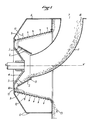
- the material to be wrung is brought into the basket by means of a bent pipe 1, which is fixed, and which feeds an inlet part 2.
- the entry piece 2 is constituted by a metal truncated cone, of axis XX 'joined and fixed by several supports 3 to the bottom 4 of the spinning basket which rotates at high speed (450 rpm) around XX '.
- This basket has a frustoconical peripheral and wringing wall 5 which has a multitude of small width openings. It rotates inside a fixed casing 6 to which the pipe 1 is itself fixed by its opening 7.
- the material is pre-drained granular carbon from the coal fines washing tanks. It flows by gravity in line 1 to the center of the basket.
- the material comes into contact in an impact zone 9 with the input part 2, which rotates at high speed with the basket.
- This part 2 in a truncated cone exerts only a very low friction force on the material; the circumferential speed setting thereof is therefore insufficient.
- the main result is that the material is distributed in packages in the basket.
- the supports 3 which rotate with the basket strike the material and disperse it in a disorderly manner. All of this results in vibrations of the basket and poor spin conditions.
- the wringer basket has three zones of significant and rapid wear: the truncated cone 2 itself, the supports 3 and a projection zone 10 of the wall. peripheral 5 of the basket, where the material is projected by centrifugal force when it leaves the input part 2, with an insufficient circumferential speed relative to that of the basket.
- the material then travels along the entire length 11 of its peripheral wall: the fine wrung out evacuates downwards at 13, while the water and the schlamms pass through the basket over the entire surface of the wringer 5, as indicated by arrows 12, and are then discharged through an opening (not shown) formed in the casing 6.
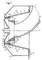
- FIG. 2 to describe a wringer basket according to the invention.
- the same references have been used as in FIG. 1 to designate the identical parts of the wringer basket not modified by the invention.
- new reference numerals have been used to designate the parts or parts of new parts in accordance with the invention.
- the entry piece produced in the spirit of the invention comprises a flat crown 14 arranged in a transverse plane perpendicular to the axis XX 'of the wringer basket.
- This crown is made of sheet metal with a thickness of 10 mm; it has an inner peripheral edge 14A by which it surrounds the fixed duct 1 and an outer peripheral edge 14B. From this outer edge 14B, a cylindrical wall 15, also made of 10 mm sheet, extends concentrically to the axis XX 'in the direction of the bottom 4 of the basket, but it is interrupted before reaching it.
- Peripherally spaced supports 16 extend radially with respect to the axis XX 'between the outer face of the cylindrical wall 15 and the peripheral wall 5 of the basket.
- This flat crown 17 has an outer peripheral edge 17A which is in contact with the peripheral wall 5 of the basket and an inner peripheral edge 17B which is widely spaced from the cylindrical wall 15. Provision may be made to directly weld the flat crown 17 to the wall device 5 of the basket; but it can also be welded to the supports 16 so that it forms part of the entry piece so that it is put in its place by its outer edge 17A against the peripheral wall 5 when the entry piece is itself inside the basket.
- the supports 16 are fixed with bolts (not shown) to the peripheral wall 5 of the basket, so that this entry piece can be easily replaced.
- the cylindrical wall 15 ends with a free circular edge 15A which faces the bottom 4 of the basket.
- the supports 16 and the flat crown 17 are set back relative to this free edge 15A, in the direction of the flow of the material.
- the basket according to the invention comprises two retention volumes of the material to be wrung, which greatly reduce, if it does not remove it, the wear of the most exposed areas and which improve the rotation of this material before it reaches the basket, as will be explained now.
- part of the material which arrives via the fixed duct 1 remains contained in the annular volume 18, with a triangular cross section, limited by the flat crown 14 and by the cylindrical wall 15.
- the material Passing over the free circular edge. 15A, the material is projected onto the cylindrical wall 5 of the basket in an area which is the projection area 10 on the conventional basket of FIG. 1. Due to the existence of the transverse flat crown 17, part of the material which travels along the cylindrical wall 5 remains contained in the annular volume 20 limited by this cylindrical wall 5 and by the crown 17. In this retention volume the material forms an annular slope on the surface 21 of which the incoming material is projected in the basket ; then the material overflows above the crown 17 and continues its progression along the wringing peripheral wall 5.
- the material is wrung out over the entire surface of the wall 5 of the basket: the fine wrung out evacuates downwards at 22, while the water and the schlamms exit according to the arrows 23 and are then evacuated by an opening of the casing 6 (not shown).
- the natural slope of material contained in the retention volumes during operation receives the shock of the flowing material, which has two advantages: on the one hand, the entry piece hardly wears out, and on the other On the other hand, the high friction between the flowing material and the contained material causes a regular distribution in the basket of the flowing material which quickly reaches a notable circumferential speed. This avoids the formation of bundles of material, vibrations of the basket, and improves the wringing conditions.
- wringer of the invention illustrated in FIG. 2 a reduction of 1% to 2% was obtained in the moisture content of the product collected. at the outlet 22, and a very regularity of this content in comparison with the same product wrung in the conventional basket of FIG. 1.
- Another important advantage of the invention is that the shocks of the flowing material against the supports 16 according to FIG. 2 are much less brutal than against the supports 3 of a conventional basket like that of FIG. 1, because the new position of these supports 16 and the best circumferential speed setting of the flowing material, mean that the rotational speeds of the material and the supports are not very different when the shocks occur. It follows, on the one hand, that the supports 16 of an entry piece according to the invention wear out much less quickly than the supports 3 in a conventional basket, and on the other hand, that these shocks do not more cause a disorderly and uneven dispersion of the material, which hampered a good spin with conventional dryers.
- Another important advantage of the invention results from the formation of the second retention volume 20 created by the transverse crown 17. Thanks to the presence of the ring of material which receives the projected material, a spinning basket conforming to the he invention has a service life more than doubled compared to a conventional basket.
- the main advantages. of the invention are: a gain in the quality and regularity of the spin, a gain in the service life of the input part, and a gain in the service life of the spin basket.
- the extractors equipped with a basket according to the invention are particularly advantageous for treating the products of washing trays for carbon fines. But they can also be applied advantageously to most industrial products to be wrung.
Landscapes
- Engineering & Computer Science (AREA)
- Health & Medical Sciences (AREA)
- Life Sciences & Earth Sciences (AREA)
- Molecular Biology (AREA)
- Mechanical Engineering (AREA)
- General Engineering & Computer Science (AREA)
- Centrifugal Separators (AREA)
- Drying Of Solid Materials (AREA)
Abstract
Description
- L'invention se rapporte aux essoreuses de matière granuleuse humide comme, par exemple, du charbon pré-égoutté sortant des bacs de lavage. Elle a plus particulièrement pour objet un panier d'essorage qui contient une pièce d'entrée qui y est fixée.
- Cette pièce fait suite à une conduite fixe d' alimentation et elle toume à grande vitesse avec le panier d'essorage ; elle reçoit de cette conduite la matière à essorer et elle dirige cette matière vers la paroi périphérique et essorante du panier.
- Jusqu'à présent, la pièce d'entrée est constituée le plus souvent par un tronc de cône qui est réuni et fixé au fond du panier par plusieurs supports. Ce tronc de cône reçoit la matière à essorer par son ouverture circulaire la plus étroite et il la dirige sur la paroi essorante du panier par son ouverture circulaire la plus large.
- Un tel tronc de cône classique a plusieurs inconvénients :
- a) comme la matière à essorer glisse sur sa face interne avec un frottement très faible, son effet de mise en vitesse circulaire de la matière est insuffisant ; il en résulte une mauvaise répartition de la matière et la formation de "paquets" dans le panier, ce qui . engendre des vibrations indésirables de ce dernier et un mauvais essorage de la matière,
- b) la matière arrive sur la pièce d'entrée avec une forte vitesse et elle use rapidement ce dernier qui doit être remplacé fréquemment,
- c) les supports du tronc de cône s'usent également très vite,
- d) la matière rencontre le panier d'essorage avec une vitesse circulaire insuffisante par rapport à la vitesse de ce panier, si bien que ce dernier s'use très vite dans la zone d'impact.
- Le but principal de l'invention est de réduire fortement ou de supprimer tous les inconvénients précités, en apportant un panier d'essoreuse ayant une pièce d'entrée dont la conception est telle que l'usure est considérablement réduite sinon totalement supprimée en même temps que la matière à essorer est entraînée en rotation plus efficacement jusqu'à une vitesse peu différente, sinon identique, à celle du panier d'essorage.
- En quittant la pièce d'entrée la matière à essorer est projetée par la force centrifuge contre la paroi périphérique essorante du panier ; cette projection est la cause d'une usure rapide de cette paroi.
- Un autre but de l'invention est aussi de parvenir à un panier d'essoreuse dont la paroi est protégée contre l'usure et dont la durée de service est notablement accrue.
- Un panier d'essoreuse centrifuge à paroi périphérique essorante tournant autour d'un axe XX', contenant une pièce d'entrée fixée à ce panier par des supports pour tourner avec lui reçoit de la matière à essorer s'écoulant d'une conduite fixe d'alimentation ; cette matière est reçue d'abord par la pièce d'entrée dans une zone d'impact puis elle est projetée sur la paroi périphérique essorante dans une zone de projection à partir de laquelle elle chemine vers un bord de sortie du panier ; selon l'invention, ce panier a une configuration présentant dans l'une au moins des zones d'impact et de projection, un volume annulaire de rétention qui retient pendant le fonctionnement une quantité de matière à essorer ayant une surface sur laquelle arrive la matière à essorer en circulation.
- Un panier conforme à l'invention peut présenter l'un ou l'autre seulement des deux volumes de rétention, mais il est grandement préférable qu'il soit pourvu des deux volumes de rétention.
- De préférence, chaque volume de rétention a un profil en section droite substantiellement triangulaire et la matière qui y est contenue pendant le fonctionnement y forme un talus naturel d'épaisseur décroissante parallèle ment à l'axe XX.
- De cette façon, la matière qui arrive et qui circule à travers le panier rencontre successivement la matière contenue dans chacun des volumes de rétention, ce qui protège efficacement contre l'usure la pièce d'entrée d'une part et la paroi périphérique d'autre part ; en outre, le frottement important qui a lieu entre la matière qui vient par la conduite fixe et la matière continue dans le volume de rétention située sur la pièce d'entrée dans la zone d'impact a pour résultat un bon entraînement en rotation de la matière avant sa projection contre la paroi périphérique essorante ; il en résulte une meilleure répartition de la matière et un affaiblissement notable des vibrations.
- Selon un mode particulier de réalisation de l'invention, la pièce d'entrée comprend d'une part une couronne disposée coaxialement au panier d'essorage dans un plan substantiellement perpendiculaire à l'axe de ce dernier avec un bord périphérique intérieur destiné à entourer dans une essoreuse la conduite d'arrivée de la matière à essorer et un bord périphérique extérieur, d'autre part une paroi cylindrique s'étendant dans le sens de l'écoulement de la matière à essorer à partir d'un endroit de ladite couronne espacé de son bord périphérique intérieur, de préférence à partir de son bord périphérique extérieur.
- De préférence, les supports de la pièce d'entrée sont fixés, d'une part à la paroi cylindrique de cette pièce d'entrée, d'autre part à la paroi périphérique du panier.
- Le rapport entre la largeur en sens radial de la couronne et la longueur en sens longitudinal de la paroi cylindrique détermine la pente du talus de matière qui séjourne dans le volume de rétention. Ce rapport doit être ajusté en fonction de la nature de la matière à essorer, afin que l'entranement en rotation de la matière en écoulement par frottement sur la matière contenue dans le volume de rétention soit convenable.
- Comme on l'a dit, quand la matière à essorer quitte le talus formé par la matière contenue dans le volume de rétention elle est projetée au-delà d'un bord de la pièce d'entrée contre la paroi périphérique du panier dans la zone de projection. Avantageusement, les supports de fixation de la pièce d'entrée au panier sont situés en aval dudit bord et de la zone de projection. Selon une caractéristique supplémentaire de l'invention, une cloison annulaire est disposée dans un plan substantiellement transversal en aval de ce même bord et de la zone de projection, avec un bord périphérique extérieur en contact avec la paroi périphérique du panier et un bord périphérique intérieur espacé de la paroi cylindrique de la pièce d'entrée.
- Cette cloison transversale limite un second volume de rétention annulaire prévu pour s'étendre jusqu'à la zone de projection et pour contenir une partie de la matière à essorer afin que la matière en circulation soit projetée sur la matière retenue.
- Cette cloison transversale peut être fixée directement à la paroi périphérique du panier ; comme il n'est pas souhaitable de réduire la longueur utile essorante de la paroi périphérique du panier, il est préférable de placer la cloison transversale au plus près en aval de la zone de projection et du bord libre annulaire défini plus haut.
- Selon un mode de réalisation de l'invention, la cloison transversale limitant le second volume de rétention est une couronne plate disposée dans un plan perpendiculaire à l' axe du panier d'essorage entre le bord libre annulaire et les supports. De préférence, cette couronne plate est adossée aux supports.
- Pour bien faire comprendre l'invention on donnera maintenant, à titre de comparaison, une description d'une pièce d'entrée classique connue et d'un exemple préféré, non limitatif, de réalisation de l'invention. On se reportera aux dessins annexés dans lesquels :
- -la figure 1 est une représentation - schématique en coupe méridienne par l'axe XX' d'un panier d'essoreuse centrifuge muni d'une pièce d'entrée de type connu,
- -la figure 2 est une vue en coupe méridienne par l'axe XX' du même panier d'essoreuse centrifuge muni d'une pièce d'entrée selon l'invention.
- Dans les deux cas, l'arrivée dans le panier de la matière à essorer est effectuée au moyen d'une conduite coudée 1, qui est fixe, et qui alimente une pièce d'entrée 2.
- Dans un panier de type connu, visible sur la figure 1, la pièce d'entrée 2 est constituée par un tronc de cône métallique, d'axe XX' réuni et fixé par plusieurs supports 3 au fond 4 du panier d'essorage qui tourne à grande vitesse (450 tours/minute) autour de XX'.
- Ce panier a une paroi périphérique et essorante 5 tronconique qui présente une multitude d'ouvertures de faible largeur. Il tourne à l'intérieur d'un carter 6 fixe auquel est elle-même fixée la conduite 1 par son ouverture 7.
- Par cette ouverture 7 est introduite dans le panier de l'essoreuse une matière 8 à essorer. Dans le présent exemple, la matière est du charbon granulaire préégoutté issu des bacs de lavage de fines à charbon. Elle s'écoule par gravité dans la conduite 1 jusqu'au centre du panier.
- Sur la figure 1, la matière entre en contact dans une zone d'impact 9 avec la pièce d'entrée 2, qui tourne à grande vitesse avec le panier. Cette pièce 2 en tronc de cône n'exerce qu'une très faible force de frottement sur la matière ; la mise en vitesse circonférentielle de celle-ci est donc insuffisante. Le résultat principal est que la matière est distribuée par paquets dans le panier. De plus, les supports 3 qui tournent avec le panier heurtent la matière et la dispersent de façon désordonnée. Il en résulte de tout cela des vibrations du panier et de mauvaises conditions d'essorage.
- En outre, avec une telle pièce d'entrée 2, le panier d'essoreuse a trois zones d'usure importante et rapide : le tronc de cône 2 lui-même, les supports 3 et une zone de projection 10 de la paroi périphérique 5 du panier, où la matière est projetée par la force centrifuge quand elle quitte la pièce d'entrée 2, avec une vitesse circonférentielle insuffisante par rapport à celle du panier.
- Par suite de la rotation du panier, la matière chemine ensuite sur toute la longueur 11 de sa paroi périphérique : les fines essorées s'évacuent vers le bas en 13, tandis que l'eau et les schlamms traversent le panier sur toute la surface de la partie essorante 5, comme indiqué par des flèches 12, et sont ensuite évacués par une ouverture (non représentée) ménagée dans le carter 6.
- On se reportera maintenant à la figure 2 pour décrire un panier d'essoreuse conforme à l'invention. Sur cette figure 2 on a utilisé les mêmes références que sur la figure 1 pour désigner les pièces identiques du panier d'essoreuse non modifiées par l'invention. Au contraire, on s'est servi de nouvelles références numériques pour désigner les pièces ou parties de pièces nouvelles conformes à l'invention.
- Sur cette figure 2, la pièce d'entrée réalisée dans l'esprit de l'invention comprend une couronne plate 14 disposée dans un plan transversal perpendiculaire à l'axe XX' du panier d'essoreuse. Cette couronne est en tôle d'une épaisseur de 10 mm ; elle a un bord périphérique intérieur 14A par lequel elle entoure le conduit fixe 1 et un bord périphérique extérieur 14B. A partir de ce bord extérieur 14B, une paroi cylindrique 15, également en tôle de 10 mm, s'étend concentriquement à l'axe XX' en direction du fond 4 du panier, mais elle s'interrompt avant de l'atteindre. Ces deux pièces sont, avantageusement réunies par soudure dans la zone de leurs bords mis en contact.
- Des supports 16 espacés circonférentiellement s'étendent radialement par rapport à l'axe XX' entre la face extérieure de la paroi cylindrique 15 et la paroi péripherique 5 du panier.
- En outre, selon un perfectionnement de l'invention, une cloison annulaire constituée par une couronne plate 17, disposée dans un plan transversal perpendiculaire à l'axe XX', est adossée aux supports 16 ; elle se trouve sur le bord extrême amont des supports 16 qui est face au fond 4 du panier. Cette couronne plate 17 a un bord périphérique extérieur 17A qui est en contact avec la paroi périphérique 5 du panier et un bord périphérique intérieur 17B qui est largement espacé de la paroi cylindrique 15. On peut prévoir de souder directement la couronne plate 17 à la paroi périphérique 5 du panier ; mais on peut aussi la souder aux supports 16 afin qu'elle fasse partie de la pièce d'entrée pour qu'elle soit mise à sa place par son bord extérieur 17A contre la paroi périphérique 5 quand la pièce d'entrée est elle-même mise en place à l'intérieur du panier. Généralement, la pièce d'entrée étant une pièce d'usure, les supports 16 sont fixés à l'aide de boulons (non représentés) à la paroi périphérique 5 du panier, pour qu'on puisse remplacer facilement cette pièce d'entrée.
- La paroi cylindrique 15 se termine par un bord libre circulaire 15A qui fait face au fond 4 du panier. Les supports 16 et la couronne plate 17 sont en retrait par rapport à ce bord libre 15A, dans le sens de l'écoulement de la matière.
- Pendant le fonctionnement, le panier conforme à l'invention comprend deux volumes de rétention de la matière à essorer, qui réduisent grandement, si elle ne la supprime pas, l'usure des zones les plus exposées et qui améliorent la mise en rotation de cette matière avant qu'elle atteigne le panier, ainsi qu'on l'expliquera maintenant.
- Dès le début du fonctionnement, une partie de la matière qui arrive par le conduit fixe 1 reste contenue dans le volume annulaire 18, à section droite triangulaire, limité par la couronne plate 14 et par la paroi cylindrique 15.
- Dans cette zone qui est, dans la pièce d'entrée classique de la figure 1, la zone d'impact de la matière avec cette pièce d'entrée, la matière forme en permanence, dans le volume annulaire 18, un talus en rotation sur lequel se déverse en permanence, sur sa face inclinée 19, la matière qui arrive par la conduite fixe. 1. Le frottement entre la matièré 9 en écoulement et la matière contenue dans le volume de rétention 18 est intense, si bien que la matière en écoulement prend de ce fait une vitesse circonférentielle déjà notable à sa sortie au-delà du bord libre circulaire 15A de la paroi cylindrique 15.
- En passant au-dessus du bord libre circulaire. 15A, la matière est projetée sur la paroi cylindrique 5 du panier dans une zone qui est la zone de projection 10 sur le panier classique de la figure 1. Du fait de l'existence de la couronne plate transversale 17, une partie de la matière qui chemine le long de la paroi cylindrique 5 reste contenue dans le volume annulaire 20 limité par cette paroi cylindrique 5 et par la couronne 17. Dans ce volume de rétention la matière forme un talus annulaire sur la surface 21 duquel est projetée la matière qui arrive dans le panier ; ensuite la matière déborde au-dessus de la couronne 17 et continue sa progression le long de la paroi périphérique essorante 5.
- La matière est essorée sur toute la surface de la paroi 5 du panier : les fines essorées s'évacuent vers le bas en 22, tandis que l'eau et les schlamms sortent suivant les flèches 23 et sont ensuite évacués par une ouverture du carter 6 (non représentée).
- Les avantages d'un panier conforme à l'invention sont multiples :
- Tout d'abord, la pièce d'entrée est très simple à exécuter, par exemple en tôle soudée, et de ce fait, elle est peu coûteuse.
- Le talus naturel de matière contenue dans les volumes de rétention pendant le fonctionnement reçoivent le choc de la matière en écoulement, ce qui présente deux avantages : d'une part, la pièce d'entrée ne s'use pratiquement pas, et d'autre part, le frottement élevé entre la matière en écoulement et la matière contenue provoque une distribution régulière dans le panier de la matière en écoulement celle-ci atteint rapidement une vitesse circonférentielle notable. On évite ainsi la formation de paquets de matière, de vibrations du panier, et on améliore les conditions d'essorage. Ainsi, en essorant du charbon préégoutté provenant de bacs de lavage du charbon, au moyen de l'essoreuse de l'invention illustrée par la figure 2, on a obtenu une réduction de 1 % à 2 % de la teneur en humidité du produit recueilli à la sortie 22, et une très grande régularité de cette teneur en comparaison du même produit essoré dans le panier classique de la figure 1.
- Un autre avantage important de l'invention est que les chocs de la matière en écoulement contre les supports 16 selon la figure 2 sont beaucoup moins brutaux que contre les supports 3 d'un panier classique comme celui de la figure 1, car la nouvelle position de ces supports 16 et la meilleure mise en vitesse circonférentielle de la matière en écoulement, font que les vitesses de rotation de la matière et des supports sont assez peu différentes lorsque les chocs se produisent. Il en résulte, d'une part , que les supports 16 d'une pièce d'entrée selon l'invention, s'usent beaucoup moins vite que les supports 3 dans un panier classique, et d'autre part, que ces chocs ne provoquent plus une dispersion désordonnée et inégale de la matière, ce qui nuisait à un bon essorage avec les essoreuses classiques.
- Un autre avantage important de l'invention résulte de la formation du second volume de rétention 20 créé par la couronne transversale 17. Grâce à la présence de l'anneau de matière qui reçoit la matière projetée, un panier d'esso rage conforme à l'invention a une durée de service plus que doublée par rapport à un panier classique.
- En résumé, les principaux avantage. de l'invention sont : un gain sur la qualité et la régularité de l'essorage, un gain sur la durée en service de la pièce d'entrée, et un gain sur la durée en service du panier d'essorage.
- Les essoreuses équipées d'un panier selon l'invention sont particulièrement intéressantes pour traiter les produits de bacs de lavage de fines à charbon. Mais elles peuvent également être appliquées avantageusement à la plupart des produits industriels à essorer.
- Il est bien entendu que l'on peut, sans sortir du cadre de l'invention, imaginer des variantes et des perfectionnements de détail, de même qu'envisager l'emploi de moyens équivalents.
Claims (9)
Priority Applications (1)
| Application Number | Priority Date | Filing Date | Title |
|---|---|---|---|
| AT86400897T ATE51350T1 (de) | 1985-04-26 | 1986-04-24 | Trockenschleuderkorb fuer feuchtes koerniges material. |
Applications Claiming Priority (2)
| Application Number | Priority Date | Filing Date | Title |
|---|---|---|---|
| FR8506402A FR2580955B1 (fr) | 1985-04-26 | 1985-04-26 | Panier d'essoreuse centrifuge pour matiere granuleuse humide |
| FR8506402 | 1985-04-26 |
Publications (3)
| Publication Number | Publication Date |
|---|---|
| EP0199654A2 true EP0199654A2 (fr) | 1986-10-29 |
| EP0199654A3 EP0199654A3 (en) | 1988-09-21 |
| EP0199654B1 EP0199654B1 (fr) | 1990-03-28 |
Family
ID=9318727
Family Applications (1)
| Application Number | Title | Priority Date | Filing Date |
|---|---|---|---|
| EP86400897A Expired - Lifetime EP0199654B1 (fr) | 1985-04-26 | 1986-04-24 | Panier d'essoreuse centrifuge pour matière granuleuse humide |
Country Status (9)
| Country | Link |
|---|---|
| US (1) | US4682423A (fr) |
| EP (1) | EP0199654B1 (fr) |
| JP (1) | JPS61250484A (fr) |
| AT (1) | ATE51350T1 (fr) |
| AU (1) | AU577758B2 (fr) |
| CA (1) | CA1274186A (fr) |
| DE (1) | DE3669833D1 (fr) |
| FR (1) | FR2580955B1 (fr) |
| ZA (1) | ZA863033B (fr) |
Families Citing this family (4)
| Publication number | Priority date | Publication date | Assignee | Title |
|---|---|---|---|---|
| US5068979A (en) * | 1990-01-11 | 1991-12-03 | Blaw Knox Food & Chemical Equipment Company | Apparatus for conditioning particulate material |
| US5155923A (en) * | 1990-01-11 | 1992-10-20 | Blaw Knox Food & Chemical Equipment Company | Apparatus and process for conditioning particulate material |
| US5230281A (en) * | 1991-07-10 | 1993-07-27 | Blaw Knox Food & Chemical Equipment Co. | Apparatus for roasting coffee beans or the like |
| GB9519248D0 (en) * | 1995-09-21 | 1995-11-22 | Mud Recovery Systems Ltd | A method of recovering drilling muds |
Family Cites Families (8)
| Publication number | Priority date | Publication date | Assignee | Title |
|---|---|---|---|---|
| BE537988A (fr) * | 1954-05-15 | |||
| FR1154064A (fr) * | 1957-01-10 | 1958-04-02 | Wintershall Ag | Perfectionnements aux essoreuses centrifuges à poussoir, résistant à l'usure |
| DE1080028B (de) * | 1959-02-27 | 1960-04-14 | Krupp Dolberg G M B H | Schub- oder Schneckenzentrifuge |
| US3970257A (en) * | 1972-10-05 | 1976-07-20 | Macdonald George James | Apparatus for reducing the size of discrete material |
| US3834631A (en) * | 1973-04-18 | 1974-09-10 | T King | Spin breaking process |
| US3831764A (en) * | 1973-06-05 | 1974-08-27 | Pennwalt Corp | Pusher-type centrifuge |
| IT1228409B (it) * | 1983-12-12 | 1991-06-14 | Cam Srl | Impianto per l'essiccamento della tornitura o rottami prima del loro utilizzo nei forni fusori e per il trattamento di rifiuti ed altri materiali di scarto |
| DE3616564A1 (de) * | 1986-05-16 | 1987-11-19 | Krupp Gmbh | Fuellvorrichtung fuer einen roehrentrockner |
-
1985
- 1985-04-26 FR FR8506402A patent/FR2580955B1/fr not_active Expired
-
1986
- 1986-04-23 US US06/854,896 patent/US4682423A/en not_active Expired - Fee Related
- 1986-04-23 ZA ZA863033A patent/ZA863033B/xx unknown
- 1986-04-24 EP EP86400897A patent/EP0199654B1/fr not_active Expired - Lifetime
- 1986-04-24 DE DE8686400897T patent/DE3669833D1/de not_active Expired - Fee Related
- 1986-04-24 AT AT86400897T patent/ATE51350T1/de not_active IP Right Cessation
- 1986-04-25 CA CA000507569A patent/CA1274186A/fr not_active Expired - Fee Related
- 1986-04-25 JP JP61094999A patent/JPS61250484A/ja active Pending
- 1986-04-28 AU AU56810/86A patent/AU577758B2/en not_active Ceased
Also Published As
| Publication number | Publication date |
|---|---|
| ZA863033B (en) | 1986-12-30 |
| FR2580955A1 (fr) | 1986-10-31 |
| FR2580955B1 (fr) | 1989-11-03 |
| JPS61250484A (ja) | 1986-11-07 |
| AU5681086A (en) | 1986-10-30 |
| ATE51350T1 (de) | 1990-04-15 |
| DE3669833D1 (de) | 1990-05-03 |
| EP0199654A3 (en) | 1988-09-21 |
| CA1274186A (fr) | 1990-09-18 |
| AU577758B2 (en) | 1988-09-29 |
| EP0199654B1 (fr) | 1990-03-28 |
| US4682423A (en) | 1987-07-28 |
Similar Documents
| Publication | Publication Date | Title |
|---|---|---|
| FR2560791A1 (fr) | Appareil de separation en continu de melanges de solides et de liquides | |
| EP0075500B1 (fr) | Machine permettant l'épluchage et le nettoyage de produits alimentaires en particulier de légumes tels que les oignons | |
| BE1006247A3 (fr) | Coude a 90 degres pour conduites de transport pneumatique. | |
| FR2460720A1 (fr) | Separateur de sable pour la preparation de pate cellulosique | |
| FR2645184A1 (fr) | Appareil de fluidisation, de degazage et de pompage d'une suspension d'une matiere cellulosique fibreuse | |
| EP0230331B1 (fr) | Machine pour l'épluchage de denrées, notamment pour l'écalage de noix | |
| FR2584306A1 (fr) | Dispositif de separation de particules non desirees presentes dans une pate de fibres | |
| EP0199654A2 (fr) | Panier d'essoreuse centrifuge pour matière granuleuse humide | |
| FR2460701A1 (fr) | Dispositif de separation de matieres solides dans un courant de liquide | |
| FR2723752A1 (fr) | Recipient doseur et diffuseur de produits de lavage | |
| FR2663240A1 (fr) | Appareil pour la separation d'un liquide et des particules solides en suspension qu'il contient. | |
| WO2000043304A1 (fr) | Dispositif de dispersion d'un materiau solide divise a l'interieur d'un recipient | |
| FR2899438A1 (fr) | Dispositif pour separer les uns des autres le pedoncules de fruits regroupes en grappes. | |
| EP0062576B1 (fr) | Essoreuse en continu | |
| FR2482874A1 (fr) | Brides de fixation de fermeture d'extremite de bol de centrifugeur | |
| EP3256754A1 (fr) | Dispositif d'equilibrage pour une machine a tambour rotatif et machine comprenant un tambour rotatif equipe d'un tel dispositif | |
| FR2630658A1 (fr) | Procede et dispositif pour la separation de produits de densites differentes, notamment des particules en suspension dans un fluide | |
| FR2479705A1 (fr) | Appareil pour fluidiser des matieres pulverulentes ou granuleuses par incorporation, dans ces matieres, d'un gaz sous pression | |
| EP0475867B1 (fr) | Porte de lavage d'une machine à baratter | |
| EP1740321B1 (fr) | Dispositif de separation d"objets | |
| EP1283293B1 (fr) | Sèche-linge à tambour horizontal rotatif | |
| FR2599272A1 (fr) | Filtre a air pour vehicules. | |
| FR2527899A1 (fr) | Dispositif d'introduction pour moissonneuse-batteuse a ecoulement axial | |
| EP0373980B1 (fr) | Récipient verseur récupérateur | |
| FR2601551A1 (fr) | Machine a desiler a rotor perfectionne. |
Legal Events
| Date | Code | Title | Description |
|---|---|---|---|
| PUAI | Public reference made under article 153(3) epc to a published international application that has entered the european phase |
Free format text: ORIGINAL CODE: 0009012 |
|
| AK | Designated contracting states |
Kind code of ref document: A2 Designated state(s): AT BE CH DE GB IT LI LU NL SE |
|
| 17P | Request for examination filed |
Effective date: 19861230 |
|
| RAP1 | Party data changed (applicant data changed or rights of an application transferred) |
Owner name: CHARBONNAGES DE FRANCE, ETABLISSEMENT PUBLIC DITE: |
|
| RAP1 | Party data changed (applicant data changed or rights of an application transferred) |
Owner name: CHARBONNAGES DE FRANCE, ETABLISSEMENT PUBLIC DIT: |
|
| PUAL | Search report despatched |
Free format text: ORIGINAL CODE: 0009013 |
|
| AK | Designated contracting states |
Kind code of ref document: A3 Designated state(s): AT BE CH DE GB IT LI LU NL SE |
|
| 17Q | First examination report despatched |
Effective date: 19890106 |
|
| GRAA | (expected) grant |
Free format text: ORIGINAL CODE: 0009210 |
|
| AK | Designated contracting states |
Kind code of ref document: B1 Designated state(s): AT BE CH DE GB IT LI LU NL SE |
|
| PG25 | Lapsed in a contracting state [announced via postgrant information from national office to epo] |
Ref country code: IT Free format text: LAPSE BECAUSE OF FAILURE TO SUBMIT A TRANSLATION OF THE DESCRIPTION OR TO PAY THE FEE WITHIN THE PRE;WARNING: LAPSES OF ITALIAN PATENTS WITH EFFECTIVE DATE BEFORE 2007 MAY HAVE OCCURRED AT ANY TIME BEFORE 2007. THE CORRECT EFFECTIVE DATE MAY BE DIFFERENT FROM THE ONE RECORDED.SCRIBED TIME-LIMIT Effective date: 19900328 Ref country code: NL Effective date: 19900328 Ref country code: SE Effective date: 19900328 Ref country code: AT Effective date: 19900328 |
|
| REF | Corresponds to: |
Ref document number: 51350 Country of ref document: AT Date of ref document: 19900415 Kind code of ref document: T |
|
| GBT | Gb: translation of ep patent filed (gb section 77(6)(a)/1977) | ||
| PGFP | Annual fee paid to national office [announced via postgrant information from national office to epo] |
Ref country code: BE Payment date: 19900427 Year of fee payment: 5 |
|
| PG25 | Lapsed in a contracting state [announced via postgrant information from national office to epo] |
Ref country code: CH Effective date: 19900430 Ref country code: LI Effective date: 19900430 Ref country code: LU Free format text: LAPSE BECAUSE OF NON-PAYMENT OF DUE FEES Effective date: 19900430 |
|
| REF | Corresponds to: |
Ref document number: 3669833 Country of ref document: DE Date of ref document: 19900503 |
|
| NLV1 | Nl: lapsed or annulled due to failure to fulfill the requirements of art. 29p and 29m of the patents act | ||
| REG | Reference to a national code |
Ref country code: CH Ref legal event code: PL |
|
| PLBI | Opposition filed |
Free format text: ORIGINAL CODE: 0009260 |
|
| 26 | Opposition filed |
Opponent name: KRUPP BUCKAU MASCHINENBAU GMBH Effective date: 19901214 |
|
| PGFP | Annual fee paid to national office [announced via postgrant information from national office to epo] |
Ref country code: GB Payment date: 19910410 Year of fee payment: 6 |
|
| PGFP | Annual fee paid to national office [announced via postgrant information from national office to epo] |
Ref country code: DE Payment date: 19910416 Year of fee payment: 6 |
|
| PG25 | Lapsed in a contracting state [announced via postgrant information from national office to epo] |
Ref country code: BE Effective date: 19910430 |
|
| BERE | Be: lapsed |
Owner name: CHARBONNAGES DE FRANCE Effective date: 19910430 |
|
| PLBM | Termination of opposition procedure: date of legal effect published |
Free format text: ORIGINAL CODE: 0009276 |
|
| STAA | Information on the status of an ep patent application or granted ep patent |
Free format text: STATUS: OPPOSITION PROCEDURE CLOSED |
|
| 27C | Opposition proceedings terminated |
Effective date: 19911115 |
|
| PG25 | Lapsed in a contracting state [announced via postgrant information from national office to epo] |
Ref country code: GB Effective date: 19920424 |
|
| GBPC | Gb: european patent ceased through non-payment of renewal fee | ||
| PG25 | Lapsed in a contracting state [announced via postgrant information from national office to epo] |
Ref country code: DE Effective date: 19930101 |