EP0198833B1 - Springs of composite material - Google Patents
Springs of composite material Download PDFInfo
- Publication number
- EP0198833B1 EP0198833B1 EP19850900474 EP85900474A EP0198833B1 EP 0198833 B1 EP0198833 B1 EP 0198833B1 EP 19850900474 EP19850900474 EP 19850900474 EP 85900474 A EP85900474 A EP 85900474A EP 0198833 B1 EP0198833 B1 EP 0198833B1
- Authority
- EP
- European Patent Office
- Prior art keywords
- spring
- end portion
- attachment member
- bush
- recess
- Prior art date
- Legal status (The legal status is an assumption and is not a legal conclusion. Google has not performed a legal analysis and makes no representation as to the accuracy of the status listed.)
- Expired
Links
- 239000002131 composite material Substances 0.000 title claims abstract description 15
- 239000000463 material Substances 0.000 claims abstract description 37
- 239000004033 plastic Substances 0.000 claims abstract description 9
- 229920003023 plastic Polymers 0.000 claims abstract description 9
- 238000000034 method Methods 0.000 claims description 10
- 239000000835 fiber Substances 0.000 claims description 7
- 229920005989 resin Polymers 0.000 claims description 6
- 239000011347 resin Substances 0.000 claims description 6
- 238000011065 in-situ storage Methods 0.000 claims description 3
- 238000002347 injection Methods 0.000 claims description 3
- 239000007924 injection Substances 0.000 claims description 3
- 230000009969 flowable effect Effects 0.000 claims description 2
- 229920002430 Fibre-reinforced plastic Polymers 0.000 abstract 1
- 239000011151 fibre-reinforced plastic Substances 0.000 abstract 1
- 229910052751 metal Inorganic materials 0.000 description 7
- 239000002184 metal Substances 0.000 description 6
- 238000004519 manufacturing process Methods 0.000 description 5
- 238000000465 moulding Methods 0.000 description 5
- 230000000694 effects Effects 0.000 description 4
- 239000003822 epoxy resin Substances 0.000 description 4
- 239000003365 glass fiber Substances 0.000 description 4
- 229920000647 polyepoxide Polymers 0.000 description 4
- 229910000831 Steel Inorganic materials 0.000 description 3
- 239000010959 steel Substances 0.000 description 3
- 239000004677 Nylon Substances 0.000 description 2
- 230000005540 biological transmission Effects 0.000 description 2
- 230000015572 biosynthetic process Effects 0.000 description 2
- 238000006243 chemical reaction Methods 0.000 description 2
- 238000013016 damping Methods 0.000 description 2
- 229920001971 elastomer Polymers 0.000 description 2
- 238000005755 formation reaction Methods 0.000 description 2
- 229920001778 nylon Polymers 0.000 description 2
- 230000000149 penetrating effect Effects 0.000 description 2
- 229920002635 polyurethane Polymers 0.000 description 2
- 239000004814 polyurethane Substances 0.000 description 2
- 238000010107 reaction injection moulding Methods 0.000 description 2
- 238000000576 coating method Methods 0.000 description 1
- 238000005260 corrosion Methods 0.000 description 1
- 230000007797 corrosion Effects 0.000 description 1
- 238000005553 drilling Methods 0.000 description 1
- 230000005484 gravity Effects 0.000 description 1
- LNEPOXFFQSENCJ-UHFFFAOYSA-N haloperidol Chemical compound C1CC(O)(C=2C=CC(Cl)=CC=2)CCN1CCCC(=O)C1=CC=C(F)C=C1 LNEPOXFFQSENCJ-UHFFFAOYSA-N 0.000 description 1
- 238000005304 joining Methods 0.000 description 1
- 239000011159 matrix material Substances 0.000 description 1
- 239000002991 molded plastic Substances 0.000 description 1
- 230000035515 penetration Effects 0.000 description 1
- 238000003825 pressing Methods 0.000 description 1
- 230000002265 prevention Effects 0.000 description 1
- 230000002787 reinforcement Effects 0.000 description 1
Images
Classifications
-
- B—PERFORMING OPERATIONS; TRANSPORTING
- B60—VEHICLES IN GENERAL
- B60G—VEHICLE SUSPENSION ARRANGEMENTS
- B60G11/00—Resilient suspensions characterised by arrangement, location or kind of springs
- B60G11/02—Resilient suspensions characterised by arrangement, location or kind of springs having leaf springs only
- B60G11/10—Resilient suspensions characterised by arrangement, location or kind of springs having leaf springs only characterised by means specially adapted for attaching the spring to axle or sprung part of the vehicle
- B60G11/12—Links, pins, or bushes
-
- F—MECHANICAL ENGINEERING; LIGHTING; HEATING; WEAPONS; BLASTING
- F16—ENGINEERING ELEMENTS AND UNITS; GENERAL MEASURES FOR PRODUCING AND MAINTAINING EFFECTIVE FUNCTIONING OF MACHINES OR INSTALLATIONS; THERMAL INSULATION IN GENERAL
- F16F—SPRINGS; SHOCK-ABSORBERS; MEANS FOR DAMPING VIBRATION
- F16F1/00—Springs
- F16F1/02—Springs made of steel or other material having low internal friction; Wound, torsion, leaf, cup, ring or the like springs, the material of the spring not being relevant
- F16F1/18—Leaf springs
- F16F1/26—Attachments or mountings
- F16F1/28—Attachments or mountings comprising cylindrical metal pins pivoted in close-fitting sleeves
-
- F—MECHANICAL ENGINEERING; LIGHTING; HEATING; WEAPONS; BLASTING
- F16—ENGINEERING ELEMENTS AND UNITS; GENERAL MEASURES FOR PRODUCING AND MAINTAINING EFFECTIVE FUNCTIONING OF MACHINES OR INSTALLATIONS; THERMAL INSULATION IN GENERAL
- F16F—SPRINGS; SHOCK-ABSORBERS; MEANS FOR DAMPING VIBRATION
- F16F1/00—Springs
- F16F1/36—Springs made of rubber or other material having high internal friction, e.g. thermoplastic elastomers
- F16F1/366—Springs made of rubber or other material having high internal friction, e.g. thermoplastic elastomers made of fibre-reinforced plastics, i.e. characterised by their special construction from such materials
- F16F1/368—Leaf springs
- F16F1/3683—Attachments or mountings therefor
- F16F1/3686—End mountings
Definitions
- This invention relates to leaf springs made of composite, fibre reinforced resin, material. More particularly, the invention relates to the provision of means whereby such a spring may be secured to, for example, a motor vehicle, where it is to be used.
- the use of composite material to manufacture leaf springs enable a considerable saving in weight to be achieved as compared with conventional steel leaf springs.
- the composite material may comprise glass fibres set within a matrix of a cured resin, for example an epoxy resin, and by the selection of suitable fibres, and orientation and disposition thereof within the spring, a spring can be manufactured which is considerably lighter than a steel leaf spring having the same properties. This is particularly advantageous for use in motor vehicles.
- one aspect of the design of leaf springs of composite material which causes some difficulty is at the ends of the spring where it is required to be attached to the vehicle. Manufacturing processes used with composite materials do not readily permit an eye to be formed at the spring end, as can easily be done in the case of a steel spring.
- an end fitting for a leaf spring made of composite material may comprise an attachment member lying within a recess extending tranf ⁇ versely of an end portion of the spring, with a metal clamping member extending around the attachment member and the end portion of the spring, longitudinally of the spring.
- the clamping member is held to the spring adjacent the end portion thereof so that the attachment member, which preferably is a tubular bush, is firmly held in the recess of the spring.
- the clamping member is of sheet metal, and various means for holding it to the spring have been proposed. This design performs satisfactorily, but can entail the use of a large number of separate components, with consequent expense, and difficulty in manufacture.
- JP-A-54 79 343 discloses a leaf spring made of fibre reinforced resin with mounting members bonded to it at its ends, the bonded surface portions being shaped to increase their area of contact and to assist in transmission of forces.
- the present invention provides a leaf spring of composite, fibre reinforced resin, material including an end portion defining an open recess extending transversely of the spring, and an attachment member lying in said recess, characterised in that said end portion and attachment member are at least partially enclosed by a plastics material which has been moulded around said end portion and attachment member in situ, to secure the attachment member and spring together.
- the moulded plastics material may be, for example, a polyurethane, an epoxy resin, or a material such as an appropriate grade of nylon.
- the material may itself incorporate fibre, e.g. glass fibre, reinforcement.
- Such materials can be injection moulded into a suitable die in which the end portion of the spring and the attachment member are placed.
- a process such as reaction injection moulding (RIM) may be utilised.
- RIM reaction injection moulding
- the attachment member may comprise a metal-rubber-metal bush, for receiving a bolt by which the spring is attached to a shackle or the like, or may comprise a tubular bush into which such a metal-rubber-metal bush can be fitted.
- Keying formations may be provided, into which the covering material can flow in its moulding process to enhance security of the attachment member.
- the spring and attachment member are held together without the use of clamps, bolts penetrating the spring, or like components.
- a rigid assembly is produced, and manufacturing tolerances are automatically taken up by the moulding process.
- the attachment member is protected against corrosion without requiring subsequent coating processes, and the assembly provides a damping effect against noise transmission.
- the invention also provides a method, as above described, of providing a composite leaf spring with means for securing it to another component.
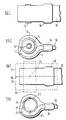
- FIG. 1 and 2 of the drawings there is illustrated a leaf spring 10 made of composite material such as glass fibres set in an epoxy resin.
- An end portion 11 of the spring defines a part circular recess extending transversely across the spring. Lying in the recess is an attachment member in the form of a bush with inner and outer tubular metal elements 12, 13 respectively and an intermediate annular rubber element 14. Such bushes are well known.
- the bush is secured to the spring by a covering 15 of plastics material, which has been moulded in situ around the bush and spring end portion.
- a part 16 of the covering extends a short distance around the spring adjacent its end portion.
- the covering material is one which is capable of being moulded around the spring end portion and bush while in flowable form, and which subsequently solidifies either by a chemical reaction or temperature change to secure the bush and spring together.
- Suitable materials for this purpose have been referred to above, e.g. plastics materials such as polyurethanes, epoxy resins, or an appropriate grade of nylon, possibly glass fibre filled.
- the assembly of bush and spring would be manufactured by placing these two components in a suitable mould or die set, into which the covering material can be introduced.
- the material could be injection moulded, or possibly poured in under gravity.
- a process such as reaction injection moulding could be used. Whichever technique is used, the mould or die must provide for prevention of the covering material penetrating the interior of the tubular element 12 of the bush, or preventing the inner and outer tubular elements 12, 13 of the bush from undergoing the slight relative movement which enables the bush to fulfill its damping function.
- FIGS. 3 and 4 of the drawings show the end portion of a leaf spring 20 of composite, fibre enforced plastics, material.
- a part circular transverse recess is defined by the end portion 21 of the spring, and in this end portion lies an attachment member in the form of a tubular bush 23.
- the bush is secured to the spring by a covering 25 of a plastics material as above, moulded around the bush and end portion of the spring.
- a part 26 of the covering material extends around a short part of the spring 20 adjacent its end portion 21.
- the bush 23 is provided with keying formations such as diametrically opposed apertures as 24, into which the covering material flows during its moulding process, so as to enhance the security of attachment of the bush to the spring.
- keying formations such as diametrically opposed apertures as 24, into which the covering material flows during its moulding process, so as to enhance the security of attachment of the bush to the spring.
- Such apertures may be provided in the bush by drilling it, possibly in place in the recess in the spring end portion whereupon an aperture 22 may be provided in the spring end portion itself to provide an even more secure keying effect.
- the die halves can be parted, the spring end removed therefrom, and the mandrel 29 withdrawn from the bush 23. If required, a rubber and metal bush can then be pressed into the bush 23. The rubber-metal bush is replaceable by pressing out of the bush 23, if required.
Landscapes
- Engineering & Computer Science (AREA)
- General Engineering & Computer Science (AREA)
- Mechanical Engineering (AREA)
- Springs (AREA)
- Laminated Bodies (AREA)
Priority Applications (1)
| Application Number | Priority Date | Filing Date | Title |
|---|---|---|---|
| AT85900474T ATE41208T1 (de) | 1983-12-20 | 1984-12-14 | Blattfedern aus mehrkomponentenwerkstoff. |
Applications Claiming Priority (4)
| Application Number | Priority Date | Filing Date | Title |
|---|---|---|---|
| GB8333846 | 1983-12-20 | ||
| GB838333846A GB8333846D0 (en) | 1983-12-20 | 1983-12-20 | Springs of composite material |
| GB8420460 | 1984-08-11 | ||
| GB848420460A GB8420460D0 (en) | 1984-08-11 | 1984-08-11 | Leaf springs |
Publications (2)
| Publication Number | Publication Date |
|---|---|
| EP0198833A1 EP0198833A1 (en) | 1986-10-29 |
| EP0198833B1 true EP0198833B1 (en) | 1989-03-08 |
Family
ID=26287122
Family Applications (2)
| Application Number | Title | Priority Date | Filing Date |
|---|---|---|---|
| EP19850900474 Expired EP0198833B1 (en) | 1983-12-20 | 1984-12-14 | Springs of composite material |
| EP84308729A Pending EP0146358A1 (en) | 1983-12-20 | 1984-12-14 | Springs of composite material |
Family Applications After (1)
| Application Number | Title | Priority Date | Filing Date |
|---|---|---|---|
| EP84308729A Pending EP0146358A1 (en) | 1983-12-20 | 1984-12-14 | Springs of composite material |
Country Status (8)
| Country | Link |
|---|---|
| EP (2) | EP0198833B1 (da) |
| AU (1) | AU561198B2 (da) |
| BR (1) | BR8407358A (da) |
| DE (1) | DE3477039D1 (da) |
| DK (1) | DK152817C (da) |
| ES (1) | ES291748Y (da) |
| GB (1) | GB2162922B (da) |
| WO (1) | WO1985002891A1 (da) |
Cited By (1)
| Publication number | Priority date | Publication date | Assignee | Title |
|---|---|---|---|---|
| DE102018206285A1 (de) | 2018-04-24 | 2019-10-24 | Ford Global Technologies, Llc | Robuste, kosteneffiziente Verbundblattfeder mit integrierter Lagerbuchse |
Families Citing this family (5)
| Publication number | Priority date | Publication date | Assignee | Title |
|---|---|---|---|---|
| GB8809573D0 (en) * | 1988-04-22 | 1988-05-25 | Gkn Technology Ltd | Leaf springs of composite material |
| GB8918693D0 (en) * | 1989-08-16 | 1989-09-27 | Gkn Technology Ltd | Leaf spring assemblies |
| FR2667122B1 (fr) * | 1990-09-21 | 1993-06-18 | Renault | Articulation souple pour extremite de ressort a lame. |
| US10059078B2 (en) * | 2012-03-23 | 2018-08-28 | Cutting Dynamics, Inc. | Injection molded composite blank and guide |
| US9393745B2 (en) * | 2012-05-15 | 2016-07-19 | Hexcel Corporation | Over-molding of load-bearing composite structures |
Family Cites Families (1)
| Publication number | Priority date | Publication date | Assignee | Title |
|---|---|---|---|---|
| GB2021731A (en) * | 1978-05-26 | 1979-12-05 | Gkn Group Services Ltd | Leaf springs of fibre-reinforced plastics |
-
1984
- 1984-12-14 GB GB08522184A patent/GB2162922B/en not_active Expired
- 1984-12-14 AU AU38331/85A patent/AU561198B2/en not_active Ceased
- 1984-12-14 EP EP19850900474 patent/EP0198833B1/en not_active Expired
- 1984-12-14 BR BR8407358A patent/BR8407358A/pt unknown
- 1984-12-14 DE DE8585900474T patent/DE3477039D1/de not_active Expired
- 1984-12-14 EP EP84308729A patent/EP0146358A1/en active Pending
- 1984-12-14 WO PCT/GB1984/000430 patent/WO1985002891A1/en not_active Ceased
- 1984-12-20 ES ES1984291748U patent/ES291748Y/es not_active Expired
-
1985
- 1985-08-19 DK DK376785A patent/DK152817C/da not_active IP Right Cessation
Cited By (1)
| Publication number | Priority date | Publication date | Assignee | Title |
|---|---|---|---|---|
| DE102018206285A1 (de) | 2018-04-24 | 2019-10-24 | Ford Global Technologies, Llc | Robuste, kosteneffiziente Verbundblattfeder mit integrierter Lagerbuchse |
Also Published As
| Publication number | Publication date |
|---|---|
| DE3477039D1 (en) | 1989-04-13 |
| DK376785D0 (da) | 1985-08-19 |
| EP0146358A1 (en) | 1985-06-26 |
| AU3833185A (en) | 1985-07-12 |
| DK376785A (da) | 1985-08-19 |
| ES291748Y (es) | 1987-01-16 |
| DK152817C (da) | 1988-10-03 |
| WO1985002891A1 (en) | 1985-07-04 |
| BR8407358A (pt) | 1986-11-25 |
| ES291748U (es) | 1986-05-16 |
| GB2162922B (en) | 1987-05-28 |
| GB8522184D0 (en) | 1985-10-09 |
| EP0198833A1 (en) | 1986-10-29 |
| AU561198B2 (en) | 1987-04-30 |
| DK152817B (da) | 1988-05-16 |
| GB2162922A (en) | 1986-02-12 |
Similar Documents
| Publication | Publication Date | Title |
|---|---|---|
| US20040222666A1 (en) | Reinforced structural body | |
| EP0198833B1 (en) | Springs of composite material | |
| WO2018166691A1 (de) | Fahrwerkskomponente für ein kraftfahrzeug und verfahren zum herstellen einer fahrwerkskomponente | |
| DE102017219061B4 (de) | Radbauteil und Verfahren zum Herstellen eines Radbauteils | |
| EP0635672A1 (de) | Druckbehälter, insbesondere Druckspeicherbehälter, Verfahren zu ihrer Herstellung und Kunststoffe hierfür | |
| EP1607602A1 (de) | Hybridgehäuse | |
| EP0134617B1 (en) | Fibre-reinforced automotive spring | |
| EP3615358A1 (de) | Mehrpunktlenker | |
| US6017481A (en) | Method of making a unitary composite steering wheel and air bag cover assembly for an inflatable air bag system | |
| EP0465824A1 (en) | Steering wheel | |
| US10843388B2 (en) | Tailgate for a motor vehicle, and method for producing such a tailgate | |
| EP0155088B1 (en) | Filament winding of articles of complex shape | |
| DE102015222298A1 (de) | Verfahren zur Herstellung eines Fahrzeugbauteils | |
| JPS5894648A (ja) | 車輌懸架用板ばね | |
| EP0419208A2 (en) | Leaf spring assemblies | |
| JPH06226778A (ja) | 端部に目玉部を有する部材とその製造方法 | |
| JPH06246774A (ja) | 端部に端部部品を有する部材とその製造方法 | |
| JPS61500742A (ja) | 複合材料のスプリング | |
| JPS61163835A (ja) | 繊維強化樹脂製フレ−ム構造体の製造方法 | |
| JPH03268934A (ja) | ステアリングホイールの芯材の製造方法 | |
| JPH09112615A (ja) | Frp板ばね | |
| JPH07144339A (ja) | ソリッドロ−ラの製造法 | |
| US20180346036A1 (en) | Composite structure and function integration during overmolding | |
| DE102009037871B4 (de) | Dämpferaufnahme zur Abstützung eines Schwingungsdämpfers an einer Fahrzeugkarosserie und Verfahren zur Herstellung einer Dämpferaufnahme | |
| JPH0340594Y2 (da) |
Legal Events
| Date | Code | Title | Description |
|---|---|---|---|
| PUAI | Public reference made under article 153(3) epc to a published international application that has entered the european phase |
Free format text: ORIGINAL CODE: 0009012 |
|
| 17P | Request for examination filed |
Effective date: 19850909 |
|
| AK | Designated contracting states |
Kind code of ref document: A1 Designated state(s): AT BE CH DE FR GB LI LU NL SE |
|
| RBV | Designated contracting states (corrected) |
Designated state(s): AT BE CH DE FR GB IT LI LU NL SE |
|
| XX | Miscellaneous (additional remarks) |
Free format text: VERBUNDEN MIT 84308729.7/0146358 (EUROPAEISCHE ANMELDENUMMER/VEROEFFENTLICHUNGSNUMMER) DURCH ENTSCHEIDUNG VOM 15.05.87. |
|
| 17Q | First examination report despatched |
Effective date: 19880202 |
|
| GRAA | (expected) grant |
Free format text: ORIGINAL CODE: 0009210 |
|
| AK | Designated contracting states |
Kind code of ref document: B1 Designated state(s): AT BE CH DE FR GB IT LI LU NL SE |
|
| REF | Corresponds to: |
Ref document number: 41208 Country of ref document: AT Date of ref document: 19890315 Kind code of ref document: T |
|
| XX | Miscellaneous (additional remarks) |
Free format text: VERBUNDEN MIT 84308729.7/0146358 (EUROPAEISCHE ANMELDENUMMER/VEROEFFENTLICHUNGSNUMMER) DURCH ENTSCHEIDUNG VOM 15.05.87. |
|
| ITF | It: translation for a ep patent filed | ||
| REF | Corresponds to: |
Ref document number: 3477039 Country of ref document: DE Date of ref document: 19890413 |
|
| ET | Fr: translation filed | ||
| PGFP | Annual fee paid to national office [announced via postgrant information from national office to epo] |
Ref country code: SE Payment date: 19891214 Year of fee payment: 6 |
|
| PGFP | Annual fee paid to national office [announced via postgrant information from national office to epo] |
Ref country code: CH Payment date: 19891218 Year of fee payment: 6 |
|
| PGFP | Annual fee paid to national office [announced via postgrant information from national office to epo] |
Ref country code: BE Payment date: 19891227 Year of fee payment: 6 |
|
| PG25 | Lapsed in a contracting state [announced via postgrant information from national office to epo] |
Ref country code: LU Free format text: LAPSE BECAUSE OF NON-PAYMENT OF DUE FEES Effective date: 19891231 |
|
| PGFP | Annual fee paid to national office [announced via postgrant information from national office to epo] |
Ref country code: NL Payment date: 19891231 Year of fee payment: 6 |
|
| PGFP | Annual fee paid to national office [announced via postgrant information from national office to epo] |
Ref country code: LU Payment date: 19900108 Year of fee payment: 6 |
|
| PLBE | No opposition filed within time limit |
Free format text: ORIGINAL CODE: 0009261 |
|
| STAA | Information on the status of an ep patent application or granted ep patent |
Free format text: STATUS: NO OPPOSITION FILED WITHIN TIME LIMIT |
|
| 26N | No opposition filed | ||
| PG25 | Lapsed in a contracting state [announced via postgrant information from national office to epo] |
Ref country code: SE Effective date: 19901215 |
|
| ITTA | It: last paid annual fee | ||
| PG25 | Lapsed in a contracting state [announced via postgrant information from national office to epo] |
Ref country code: LI Effective date: 19901231 Ref country code: CH Effective date: 19901231 Ref country code: BE Effective date: 19901231 |
|
| BERE | Be: lapsed |
Owner name: GKN TECHNOLOGY LTD Effective date: 19901231 |
|
| PG25 | Lapsed in a contracting state [announced via postgrant information from national office to epo] |
Ref country code: NL Effective date: 19910701 |
|
| NLV4 | Nl: lapsed or anulled due to non-payment of the annual fee | ||
| REG | Reference to a national code |
Ref country code: CH Ref legal event code: PL |
|
| EUG | Se: european patent has lapsed |
Ref document number: 85900474.9 Effective date: 19910910 |
|
| PGFP | Annual fee paid to national office [announced via postgrant information from national office to epo] |
Ref country code: GB Payment date: 19991208 Year of fee payment: 16 Ref country code: FR Payment date: 19991208 Year of fee payment: 16 |
|
| PGFP | Annual fee paid to national office [announced via postgrant information from national office to epo] |
Ref country code: DE Payment date: 19991220 Year of fee payment: 16 Ref country code: AT Payment date: 19991220 Year of fee payment: 16 |
|
| PG25 | Lapsed in a contracting state [announced via postgrant information from national office to epo] |
Ref country code: GB Free format text: LAPSE BECAUSE OF NON-PAYMENT OF DUE FEES Effective date: 20001214 Ref country code: AT Free format text: LAPSE BECAUSE OF NON-PAYMENT OF DUE FEES Effective date: 20001214 |
|
| GBPC | Gb: european patent ceased through non-payment of renewal fee |
Effective date: 20001214 |
|
| PG25 | Lapsed in a contracting state [announced via postgrant information from national office to epo] |
Ref country code: FR Free format text: LAPSE BECAUSE OF NON-PAYMENT OF DUE FEES Effective date: 20010831 |
|
| REG | Reference to a national code |
Ref country code: FR Ref legal event code: ST |
|
| PG25 | Lapsed in a contracting state [announced via postgrant information from national office to epo] |
Ref country code: DE Free format text: LAPSE BECAUSE OF NON-PAYMENT OF DUE FEES Effective date: 20011002 |